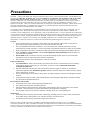
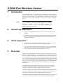
1
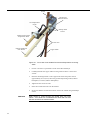
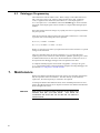
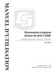
USER MANUAL CS506 Fuel Moisture Sensor Issued: 8.9.15 Copyright © 1998-2015 Campbell Scientific, Inc. Printed under licence by Campbell Scientific Ltd. CSL 892 Guarantee This equipment is guaranteed against defects in materials and workmanship. This guarantee applies for twelve months from date of delivery. We will repair or replace products which prove to be defective during the guarantee period provided they are returned to us prepaid. The guarantee will not apply to: Equipment which has been modified or altered in any way without the written permission of Campbell Scientific Batteries Any product which has been subjected to misuse, neglect, acts of God or damage in transit. Campbell Scientific will return guaranteed equipment by surface carrier prepaid. Campbell Scientific will not reimburse the claimant for costs incurred in removing and/or reinstalling equipment. This guarantee and the Company’s obligation thereunder is in lieu of all other guarantees, expressed or implied, including those of suitability and fitness for a particular purpose. Campbell Scientific is not liable for consequential damage. Please inform us before returning equipment and obtain a Repair Reference Number whether the repair is under guarantee or not. Please state the faults as clearly as possible, and if the product is out of the guarantee period it should be accompanied by a purchase order. Quotations for repairs can be given on request. It is the policy of Campbell Scientific to protect the health of its employees and provide a safe working environment, in support of this policy a “Declaration of Hazardous Material and Decontamination” form will be issued for completion. When returning equipment, the Repair Reference Number must be clearly marked on the outside of the package. Complete the “Declaration of Hazardous Material and Decontamination” form and ensure a completed copy is returned with your goods. Please note your Repair may not be processed if you do not include a copy of this form and Campbell Scientific Ltd reserves the right to return goods at the customers’ expense. Note that goods sent air freight are subject to Customs clearance fees which Campbell Scientific will charge to customers. In many cases, these charges are greater than the cost of the repair. Campbell Scientific Ltd, 80 Hathern Road, Shepshed, Loughborough, LE12 9GX, UK Tel: +44 (0) 1509 601141 Fax: +44 (0) 1509 601091 Email: [email protected] www.campbellsci.co.uk PLEASE READ FIRST About this manual Please note that this manual was originally produced by Campbell Scientific Inc. primarily for the North American market. Some spellings, weights and measures may reflect this origin. Some useful conversion factors: Area: 1 in2 (square inch) = 645 mm2 Length: 1 in. (inch) = 25.4 mm 1 ft (foot) = 304.8 mm 1 yard = 0.914 m 1 mile = 1.609 km Mass: 1 oz. (ounce) = 28.35 g 1 lb (pound weight) = 0.454 kg Pressure: 1 psi (lb/in2) = 68.95 mb Volume: 1 UK pint = 568.3 ml 1 UK gallon = 4.546 litres 1 US gallon = 3.785 litres In addition, while most of the information in the manual is correct for all countries, certain information is specific to the North American market and so may not be applicable to European users. Differences include the U.S standard external power supply details where some information (for example the AC transformer input voltage) will not be applicable for British/European use. Please note, however, that when a power supply adapter is ordered it will be suitable for use in your country. Reference to some radio transmitters, digital cell phones and aerials may also not be applicable according to your locality. Some brackets, shields and enclosure options, including wiring, are not sold as standard items in the European market; in some cases alternatives are offered. Details of the alternatives will be covered in separate manuals. Part numbers prefixed with a “#” symbol are special order parts for use with non-EU variants or for special installations. Please quote the full part number with the # when ordering. Recycling information At the end of this product’s life it should not be put in commercial or domestic refuse but sent for recycling. Any batteries contained within the product or used during the products life should be removed from the product and also be sent to an appropriate recycling facility. Campbell Scientific Ltd can advise on the recycling of the equipment and in some cases arrange collection and the correct disposal of it, although charges may apply for some items or territories. For further advice or support, please contact Campbell Scientific Ltd, or your local agent. Campbell Scientific Ltd, 80 Hathern Road, Shepshed, Loughborough, LE12 9GX, UK Tel: +44 (0) 1509 601141 Fax: +44 (0) 1509 601091 Email: [email protected] www.campbellsci.co.uk Precautions DANGER — MANY HAZARDS ARE ASSOCIATED WITH INSTALLING, USING, MAINTAINING, AND WORKING ON OR AROUND TRIPODS, TOWERS, AND ANY ATTACHMENTS TO TRIPODS AND TOWERS SUCH AS SENSORS, CROSSARMS, ENCLOSURES, ANTENNAS, ETC. FAILURE TO PROPERLY AND COMPLETELY ASSEMBLE, INSTALL, OPERATE, USE, AND MAINTAIN TRIPODS, TOWERS, AND ATTACHMENTS, AND FAILURE TO HEED WARNINGS, INCREASES THE RISK OF DEATH, ACCIDENT, SERIOUS INJURY, PROPERTY DAMAGE, AND PRODUCT FAILURE. TAKE ALL REASONABLE PRECAUTIONS TO AVOID THESE HAZARDS. CHECK WITH YOUR ORGANIZATION'S SAFETY COORDINATOR (OR POLICY) FOR PROCEDURES AND REQUIRED PROTECTIVE EQUIPMENT PRIOR TO PERFORMING ANY WORK. Use tripods, towers, and attachments to tripods and towers only for purposes for which they are designed. Do not exceed design limits. Be familiar and comply with all instructions provided in product manuals. Manuals are available at www.campbellsci.eu or by telephoning +44(0) 1509 828 888 (UK). You are responsible for conformance with governing codes and regulations, including safety regulations, and the integrity and location of structures or land to which towers, tripods, and any attachments are attached. Installation sites should be evaluated and approved by a qualified engineer. If questions or concerns arise regarding installation, use, or maintenance of tripods, towers, attachments, or electrical connections, consult with a licensed and qualified engineer or electrician. General • Prior to performing site or installation work, obtain required approvals and permits. Comply with all governing structure-height regulations, such as those of the FAA in the USA. • Use only qualified personnel for installation, use, and maintenance of tripods and towers, and any attachments to tripods and towers. The use of licensed and qualified contractors is highly recommended. • Read all applicable instructions carefully and understand procedures thoroughly before beginning work. • Wear a hardhat and eye protection, and take other appropriate safety precautions while working on or around tripods and towers. • Do not climb tripods or towers at any time, and prohibit climbing by other persons. Take reasonable precautions to secure tripod and tower sites from trespassers. • Use only manufacturer recommended parts, materials, and tools. Utility and Electrical • You can be killed or sustain serious bodily injury if the tripod, tower, or attachments you are installing, constructing, using, or maintaining, or a tool, stake, or anchor, come in contact with overhead or underground utility lines. • Maintain a distance of at least one-and-one-half times structure height, or 20 feet, or the distance required by applicable law, whichever is greater, between overhead utility lines and the structure (tripod, tower, attachments, or tools). • Prior to performing site or installation work, inform all utility companies and have all underground utilities marked. • Comply with all electrical codes. Electrical equipment and related grounding devices should be installed by a licensed and qualified electrician. Elevated Work and Weather • Exercise extreme caution when performing elevated work. • Use appropriate equipment and safety practices. • During installation and maintenance, keep tower and tripod sites clear of un-trained or non-essential personnel. Take precautions to prevent elevated tools and objects from dropping. • Do not perform any work in inclement weather, including wind, rain, snow, lightning, etc. Maintenance • Periodically (at least yearly) check for wear and damage, including corrosion, stress cracks, frayed cables, loose cable clamps, cable tightness, etc. and take necessary corrective actions. • Periodically (at least yearly) check electrical ground connections. WHILE EVERY ATTEMPT IS MADE TO EMBODY THE HIGHEST DEGREE OF SAFETY IN ALL CAMPBELL SCIENTIFIC PRODUCTS, THE CUSTOMER ASSUMES ALL RISK FROM ANY INJURY RESULTING FROM IMPROPER INSTALLATION, USE, OR MAINTENANCE OF TRIPODS, TOWERS, OR ATTACHMENTS TO TRIPODS AND TOWERS SUCH AS SENSORS, CROSSARMS, ENCLOSURES, ANTENNAS, ETC. Contents PDF viewers: These page numbers refer to the printed version of this document. Use the PDF reader bookmarks tab for links to specific sections. 1. Introduction ................................................................ 1 2. Cautionary Statements .............................................. 1 3. Initial Inspection ........................................................ 1 4. Overview ..................................................................... 1 4.1 4.2 Dowel Selection ................................................................................... 2 CS506 Measurement Technique .......................................................... 2 5. Specifications ............................................................ 3 6. Installation .................................................................. 3 6.1 6.2 6.3 009620 Mounting Kit ........................................................................... 3 Wiring .................................................................................................. 5 Datalogger Programming ..................................................................... 6 7. Maintenance ............................................................... 6 Appendix A. Example Program .................................................. A-1 A.1 CR1000 Programming .................................................................... A-1 6-1. 6-2. Front view of the 009620 fuel moisture/temperature mounting stake .. 4 Back view of the 009620 fuel moisture/temperature mounting stake .. 5 6-1. CS506 Wiring ...................................................................................... 5 Figures Table i CS506 Fuel Moisture Sensor 1. Introduction The CS506 fuel moisture sensor measures the moisture content of the 009619 10hour fuel moisture stick. The 009619 emulates the moisture content of similarly sized twigs on the forest floor. The CS506/009619 combination is used to assess forest fire fuel and is often incorporated in our prewired or custom fire-weather stations. NOTE 2. 3. 4. This manual provides information only for CRBasic dataloggers. It is also compatible with our retired Edlog dataloggers. For Edlog datalogger support, see an older manual at www.campbellsci.com/old-manuals or contact a Campbell Scientific application engineer for assistance. Cautionary Statements READ AND UNDERSTAND the Precautions section at the front of this manual. Avoid touching the dowel of the #009619 fuel moisture stick with your bare hands. Your hands can contaminate the dowel with oils and dirt that can affect the measurements. Initial Inspection Upon receipt of the CS506 and 009619, inspect the packaging and contents for damage. File damage claims with the shipping company. The model number and cable length are printed on a label at the connection end of the cable. Check this information against the shipping documents to ensure the expected product and cable length are received. Overview Traditionally, the standard fuel moisture stick consists of a rack of four 0.5 inch diameter ponderosa pine dowels. The resulting rack is about 20 inches long with an oven-dry weight of 100 grams. The characteristic time constant of the rack is 10 hours. The rack is mounted 12 inches or about 30 centimetres above the forest floor. The rack is left outside continually exposed to the same conditions as forest fuels. The rack absorbs and desorbs moisture from its surroundings. As the rack transfers moisture, its weight changes. Periodic weighing of the rack determines changes in moisture content and provides an indication of moisture changes in forest fuels. A disadvantage of the traditional weighing racks is that you cannot remotely monitor the changing fuel conditions. Campbell Scientific’s CS506/009619 combination supports this while providing similar measurements. The CS506 consists of a printed circuit board encapsulated in a waterproof epoxy housing. A shielded four-conductor cable is connected to the circuit board to supply power, enable the electronics, and monitor the signal output. The 009619 10-hour fuel moisture stick includes two stainless steel strips pressed into grooves carved in a carefully selected USFS standard ponderosa dowel. 1 Nylon tie wraps secure the dowel to the stainless-steel strips. The 009619 connects to the CS506 with two Phillips head screws. Because the complete dowel surface is accessible for moisture exchange, the response of the CS506 is similar to that of the traditional weighing rack. 4.1 Dowel Selection The 009619 Fuel Moisture Stick uses the same dowel as used by the traditional weighing fuel moisture racks. No artificial materials such as epoxy sealant are added to the dowel that would adversely influence its natural characteristics. To optimize stick-to-stick repeatability and to allow stick interchangeability without individual calibration, two additional sorts are performed on the dowels before they are selected to be used as a 009619 fuel moisture stick. First, the dowels are sorted dry by density to improve accuracy in the dry range of 0 to 15%. Second, the dowels are sorted after a 50-minute soak by weight to reduce probeto-probe time response variation and minimize variability in the wet range of 20 to 50%. Even after careful selection and sorting is performed to choose the most representative dowels, the majority of measurement error is due to the variability of wood. Wood’s ability to transfer moisture is dependent on many variables, primarily cell structure and wood resin content. These variables change over time and after repeated wetting and drying cycles. Only a small amount of overall measurement error is due to the electronic circuitry. 4.2 CS506 Measurement Technique High speed electronic components on the circuit board are configured to oscillate when power is applied. The output of the circuit is connected to the 009619 fuel moisture stick which acts as a wave guide. The oscillation frequency and therefore output signal of the circuit is dependent on the dielectric constant of the media surrounding the stainless steel strips. The dielectric constant is predominantly dependent on the water content of the wood. Digital circuitry scales the oscillation frequency to an appropriate range that our dataloggers can measure. The CS506 output is essentially a square wave with an amplitude of 0.7 Vdc. The frequency of the square wave output ranges from approximately 31 to 58 kHz. Its output period ranges from 17 to 32 s. 2 User Manual 5. Specifications Features: Companion product to CS205/107 fuel temperature sensor; can be mounted on the same stake Can automatically monitor changing fuel conditions without having to visit the measurement site Compatible telemetry options include spread spectrum radios, narrowband radios, cellular phones, and satellite transmitters Compatible with Campbell Scientific CRBasic dataloggers: CR6, CR800, CR850, CR1000, CR3000, and CR5000 *Fuel moisture accuracy: (with a new stick) 90% of all range measurements 0 to 10% 1.25% 10 to 20% 2.00% 20 to 30% 3.40% 30 to 50% 4.11% rms error 0.74% 0.90% 1.94% 2.27% Range: 0 to 50% Power Supply: 5 Vdc minimum to 18 Vdc maximum Enable voltage: off at 0 V (<1 Vdc) on at 5 V (>4 Vdc maximum 18 Vdc) Current usage: 65 mA active/ 45 µA quiescent Output signal: 0.7 V square wave with an output frequency of approximately 31 to 58 kHz. Weight: <0.5 kg (<1 lb) Dimensions Dowel: Electronics: 1.3 cm (0.5 in) diameter, 50.8 cm (20 in) long 10.2 x 6.4 x 1.9 cm (4 x 2.5 x 0.75 in) *The above accuracy is a static accuracy derived at slow changing conditions with experimental data for the CS505. 6. Installation 6.1 009620 Mounting Kit The CS506/009619 is typically mounted with the CS205/107 using the 009620 Mounting Kit ( Figure 6-1 and Figure 6-2). The kit’s bracket places the probes in a horizontal position. 3 U-bolt CS506 Fuel Moisture Sensor 107 Temperature Probe Phillips-head Screws CS205 10-Hour Fuel Temperature Stick Cable Ties 009619 Ponderosa Pine Dowel Copper Stake Figure 6-1. Front view of the 009620 fuel moisture/temperature mounting stake CAUTION 4 1. Choose a site that is representative of the forest-floor duff layer. 2. Carefully hammer the copper stake into the ground so that it is secure and vertical. 3. Place the mounting bracket on the copper stake so that the probes will be approximately 30 cm (12 in) above the ground and pointing south (northern hemisphere) or north (southern hemisphere). 4. Tighten the nuts on the U-bolts. 5. Insert the CS506 electronics into the bracket. 6. Secure the 009619 10-hour fuel moisture stick to the CS506 using the Phillips screws. Wear gloves to avoid touching the dowel with your bare hands. Your hands can contaminate the dowel with oils and dirt that can affect the measurements. User Manual 009619 Ponderosa Pine Dowel CS506 Sensor CS205 Stick Compression Fitting Cable Tie 107 Temperature Probe Figure 6-2. Back view of the 009620 fuel moisture/temperature mounting stake 7. Insert the CS205 fuel temperature stick into the mounting stake’s compression fitting. 8. Insert the 107 temperature probe into the CS205 stick. 9. Tighten the compression fitting so that it compresses the split wood and snugly holds the 107 probe. 10. Use the ultraviolet light resistant cable ties included in the 009620 mounting kit to secure the cables. One cable tie passes through the two slots in the bracket to loosely secure the cable of the CS205/107 (Figure 6-2). The other two cable ties secure both cables to the copper stake ( 11. Figure 6-1). 6.2 Wiring Connections to Campbell Scientific dataloggers are given in Table 6-1. Table 6-1. CS506 Wiring Colour Description CR800, CR1000, CR3000, CR5000 CR6 Red Power 12 V 12 V Black Ground G G Green Signal Single-Ended Channel Universal Channel Orange Enable Control Port Control Port Clear Ground ⏚ ⏚ 5 6.3 Datalogger Programming The CS506 has a built-in enable circuit. When voltage on the enable lead is less than 1 Vdc, the sensor is off. When a voltage greater than 4 Vdc, commonly 5 Vdc, is applied to the enable lead, the sensor is on. The output signal is a 0.7 volt square wave. The CRBasic instruction PeriodAvg() is used to measure the period of the output signal in microseconds on a single-ended analogue input channel. Since fuel moisture does not change very rapidly, the sensor is typically measured only once per hour. After the period of the output signal in microseconds is measured, it is converted to percent water content using one of two equations: ≤ = 7.6298 – 130.0904 = 0.0406 + 3.7685 – 73.7974 Where is the percent of water by weight in the fuel moisture stick and is period average in microseconds. There is a slight disconnect in the two equations at 17.7 s where the linear equation gives a water content of 4.98% while the quadratic equation gives 5.68%. A sudden small increase or decrease in the measured water content near 5% is to be expected as the datalogger changes from one equation to the other. A complete CR1000 program can be found in Appendix A, Example Program (p. A-1). Programming basics and programming examples for Edlog dataloggers are provided at www.campbellsci.com\old-manuals. 7. Maintenance Replace the 009619 Fuel Moisture Stick each spring; more frequent replacements may be required in some environments. The more wet/dry cycles the dowel experiences, the more frequently it will need to be replaced. To change the 009619 Fuel Moisture Stick, loosen the Phillips-head screws and remove the old fuel moisture stick. Replace it with the new 009619 Fuel Moisture Stick and tighten the screws. CAUTION 6 Wear gloves to avoid touching the dowel of the 009619 fuel moisture stick with your bare hands. Your hands can contaminate the dowel with oils and dirt that can affect the measurements. Appendix A. Example Program A.1 CR1000 Programming The following program measures a CS506 fuel moisture sensor using the CRBasic PeriodAvg() instruction. 'CR1000 'CR1000 Program for CS506 'Declare Variables and Units Public FuelM Public PA_uS Units FuelM=% Units PA_uS=uSec 'Define Data Tables DataTable(Table1,True,-1) DataInterval(0,60,Min,10) Sample(1,FuelM,FP2) Sample(1,PA_uS,FP2) EndTable 'Main Program BeginProg Scan(10,Sec,1,0) 'CS506 Fuel Moisture Sensor measurement FuelM and PA_uS: If IfTime(0,1,Hr) Then PortSet (1,1) PeriodAvg(PA_uS,1,mV250,1,0,0,100,10,1,0) PortSet (1,0) If PA_uS <= 17.7 Then FuelM = 7.6298* PA_uS - 130.0904 Else FuelM= 0.0406* PA_uS ^2 + 3.7685 * PA_uS -73.7974 EndIf EndIf 'Call Data Tables and Store Data CallTable(Table1) NextScan EndProg A-1 CAMPBELL SCIENTIFIC COMPANIES Campbell Scientific, Inc. (CSI) 815 West 1800 North Logan, Utah 84321 UNITED STATES www.campbellsci.com [email protected] Campbell Scientific Africa Pty. Ltd. (CSAf) PO Box 2450 Somerset West 7129 SOUTH AFRICA www.csafrica.co.za [email protected] Campbell Scientific Australia Pty. Ltd. (CSA) PO Box 8108 Garbutt Post Shop QLD 4814 AUSTRALIA www.campbellsci.com.au [email protected] Campbell Scientific do Brazil Ltda. (CSB) Rua Apinagés, nbr. 2018 - Perdizes CEP: 01258-00 São Paulo SP BRAZIL www.campbellsci.com.br [email protected] Campbell Scientific Canada Corp. (CSC) 14532 – 131 Avenue NW Edmonton, Alberta T5L 4X4 CANADA www.campbellsci.ca [email protected] Campbell Scientific Centro Caribe S.A. (CSCC) 300N Cementerio, Edificio Breller Santo Domingo, Heredia 40305 COSTA RICA www.campbellsci.cc [email protected] Campbell Scientific Ltd. (CSL) 80 Hathern Road, Shepshed, Loughborough LE12 9GX UNITED KINGDOM www.campbellsci.co.uk [email protected] Campbell Scientific Ltd. (France) 3 Avenue de la Division Leclerc 92160 ANTONY FRANCE www.campbellsci.fr [email protected] Campbell Scientific Spain, S. L. Avda. Pompeu Fabra 7-9 Local 1 - 08024 BARCELONA SPAIN www.campbellsci.es [email protected] Campbell Scientific Ltd. (Germany) Fahrenheitstrasse13, D-28359 Bremen GERMANY www.campbellsci.de [email protected] Campbell Scientific (Beijing) Co., Ltd. 8B16, Floor 8 Tower B, Hanwei Plaza 7 Guanghua Road, Chaoyang, Beijing 100004 P.R. CHINA www.campbellsci.com [email protected] Please visit www.campbellsci.com to obtain contact information for your local US or International representative.