1
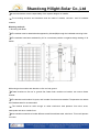
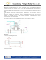
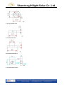
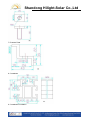
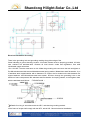
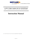
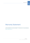
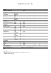
Shandong Hilight-Solar Co.,Ltd
Installation Safety Instructions
Maintenance Manual
Shandong Hilight-solar Co.,Ltd Preparing
2011
Shandong Hilight-Solar Co.,Ltd
Installation | Safety instructions | Maintenance
Photovoltaic modules user manual
Please carefully read the following installation and safety instructions.
Non-compliance with these instructions may void the module warranty.
Purpose of this guide
This guide contains information regarding the installation and safe handling of Hilight-solar photovoltaic
modules (hereafter referred to as "modules").
All instructions should be read and understood before attempting installation. If there are any
questions, please contact your dealer or Hilight-solar for further information.
The installer should conform to all safety precautions in the guide when installing modules.Before
installing a solar photovoltaic system,the installer should become familiar with the mechanical and
electrical requirements for photovoltaic systems.
Keep this guide in a safe place for future reference.
General
Installing solar photovoltaic systems requires specialized skills and knowledge. The installer
assumes all risk of injury, including risk of electric shock. Module installation should be performed only
by qualified persons.
All modules come with a permanently attached junction box and #12 AWG (4
mm2) wire terminated in PV connectors.
Exercise caution when wiring or handling modules exposed to sunlight.
When disconnecting wires connected to a photovoltaic module that is exposed to sunlight, an
electric arc may occur. Arcs can cause burns, start fires or otherwise create safety problems. Exercise
caution when disconnecting wiring on modules exposed to sunlight.
Photovoltaic solar modules convert light energy to direct-current electrical energy, and are designed
for outdoor use. Proper design of support structures is the responsibility of the system designer and
installer.
Modules may be ground mounted, pole mounted, or mounted on rooftops.
Do not attempt to disassemble the module, and do not remove any attached nameplates or
components.
Doing so will void the warranty.
Do not apply paint or adhesive to the module.
Shandong Hilight-Solar Co.,Ltd
Do not use mirrors or other hardware to artificially concentrate sunlight on the module.
When installing modules, observe all applicable local, regional and national codes and regulations.
Obtain a building and/or electrical permit where required.
Safety precautions for installing a solar photovoltaic system
Solar modules produce electrical energy when exposed to sunlight.
Only connect modules with the same rated output current in series. If modules are connected in
series, the total voltage is equal to the sum of the individual module voltages.
Only connect modules or series combinations of modules with the same voltage in parallel. If
modules are connected in parallel, the number of parallel module
= 1 + I( Max. over-current rating)/ Isc( short current)
Keep children well away from the system while transporting and installing mechanical and electrical
components.
Completely cover all modules with an opaque material during installation to prevent electricity from
being generated.
Do not wear metallic rings, watchbands, ear, nose, or lip rings or other metallic devices while
installing or troubleshooting photovoltaic systems.
Use appropriate safety equipment (insulated tools,insulating gloves,etc) approved for use on
electrical installations.
Observe the instructions and safety precautions for all other components used in the system,
including wiring and cables, connectors, DC-breakers, mounting hardware, inverters, etc.
Use only equipment, connectors, wiring and mounting hardware suitable for use in a photovoltaic
system.
Always use the same type of module within a particular photovoltaic system.
Under normal operating conditions, PV modules will produce currents and voltages that are
different than those listed in the date sheet. Data sheet values are applicable at standard test data.
Short-circuit current and open-circuit voltages should be multiplied by a factor of 1.25 when
determining component voltage ratings, conductor ampacity, fuse sizes and size of controls connected
to the module or system output.Refer to Section 690-8 of the National Electrical Code (NEC) for an
additional multiplying factor of 125 percent (80 percent de-rating) which may be applicable.
Shandong Hilight-Solar Co.,Ltd
General installation notes
Drainage holes must not be covered with parts of the mounting system. The junction box has a
breather port which must be mounted facing downward and cannot be exposed to the rain. The junction
box should be on the higher side of the module when it is mounted in order to orient the breather port
correctly.
Do not lift the module by grasping the module's junction box or electrical leads.
Do not stand or step on module.
Do not drop the module or allow objects to fall on the module.
Do not place any heavy objects on the module.
Inappropriate transport and installation may damage the module glass or frame.
Mechanical Installation Selecting the location
Select a suitable location for installation of the module.
For optimum performance, the module must be facing true south in northern latitudes and true north
in southern latitudes.
For detailed information on optimal module orientation, refer to standard solar photovoltaic
installation guides or a reputable solar installer or systems integrator.
The module should not be shaded at any time of the day.
Do not install the module near equipment or in locations where flammable gases can be generated
or collected.
Selecting the proper mounting structure and hardware
Observe all instructions and safety precautions included with the mounting system to be used with
the module.
Do not drill holes in the glass surface of the module. Doing so will void the warranty.
Do not drill additional mounting holes in the module frame. Doing so will void the warranty.
Modules must be securely attached to the mounting structure using 8 mounting points for normal
installation.
Shandong Hilight-Solar Co.,Ltd
Load calculations are the responsibility of the system designer or installer.
The mounting structure and hardware must be made of durable, corrosion- and UV-resistant
material.
Mounting methods
1. Mounting with Bolts
The module must be attached and supported by 8 bolts(M8) through the indicated mounting holes.
The modules have been evaluated by UL for a maximum positive or negative design loading of 30
lbs/ft2.
2.Mounting solar modules with bracket on flat roof and ground
Fasten bracket on flat roof or ground first, fasten solar modules on bracket, use nuts to fasten
bracket.
The bracket would endure 20 years, and is made of anticorrosive material. Temperature zinc steels
and Stainless steel is recommended.
The bracket should be solid enough to resist continuous load pressure from wind ,snow,
earthquake and other outside force.
Use insulation materials to isolate different metal like stainless steel, aluminum. This would prevent
corrosion.
Shandong Hilight-Solar Co.,Ltd
insert screw into flat gasket insert screw into installation hole both onthe modules and supporting
frame
insert screw into flat gasket and spring gasket, then apply nut on the screw fasten it.
refer to the following form for supporting bracket's slope angle
3. Other
The recommended standoff height is 5 cm. If other mounting means are employed this may affect
Shandong Hilight-Solar Co.,Ltd
the UL Listing.
Direction of module installation: PV module are rectangle shaped; PV module array longitudinal
installation (the way that installs the module by long side longitudinal) is mostly used because the
transverse installation (the way that installs the module by long side transversely) has less rain cleaning
ability.
For distance between the modules, longitudinal distance (along the roof gradient) should be
enough for installation and disassembly; transverse distance should be 3-10cm. Other mounting
methods are acceptable as long as the minimum requirements as described above. Above
requirements are only basic instructions.
For example, on slant roof ,Mono-crystalline Cell Module ,Poly-crystalline Cell Module
Accessory:
1. Hexagon Self-locking Bolt M8*35
2. Hexagon Nut M10
Shandong Hilight-Solar Co.,Ltd
3. Spring Washer M10
4. Flat Washers M10
5.Nonstandard Nut M10
6. Nonstandard Bolt M10
Shandong Hilight-Solar Co.,Ltd
7. Pressure Plate
8 .Crossbeam
9. Crossbeam Foundation
Shandong Hilight-Solar Co.,Ltd
Electrical Installation Grounding
There is the grounding hole and grounding marking along either edge of the
frame indicating a ground bonding location. All module frames must be properly grounded. All bolts,
nuts, washers are stainless-steel. Observe all local electric codes and regulations. Use solid
uninsulated copper wire sizes
10 or 12 AWG. The wire must have no nick. Make the grounding wire connect to the bolt and tighten it.
Put M4 stainless steel bolt across M4stainless steel spring washer, M4stainless steel flat washer, 2 pc
of stainless steel cupped washer with a diameter of 4 Copper wire is winded on the bolt between two
cupped washers. and M4 stainless steel star washer, and then through the grounding hole on the
aluminum frame components, M4 stainless steel flat washer And spring washer, at last tighten them
with the stainless steel M4 nut. (TORQUE 4N.M )
Details for wiring in accordance with the NEC, and that the grounding method
of the frame of arrays shall comply with the NEC, article 250. General electrical installation
Shandong Hilight-Solar Co.,Ltd
Do not use modules of different configurations in the same system.
This module is supplied with Multi Contact connectors for electrical connections.
Refer to Section 690.31 of the NEC to determine appropriate types and temperature ratings of
conductors. Wiring should be #12 AWG, 4 mm2 (minimum) and must be temperature rated at 90 °C
(minimum).
Completely cover system modules with an opaque material to prevent electricity from being
generated while disconnecting conductors.
Refer to Sections 690.8 and 310 of the NEC to determine overcurrent,
Conductor ampacity and size requirements.
In Canada, installation shall be in accordance with CSA C22.1, Safety Standard for Electrical
Installations, Canadian Electrical Code, Part 1.
For best performance, ensure that positive and negative DC wires run closely together avoiding
loops.
Application class is class A.
Modules rated for use in this application class may be used in systems operating at greater than 50V
DC or 240W, where general contact access is anticipated. Modules qualified for safety through this part
of IEC61730 and IEC61730-2 and within this application class are considered to meet the requirements
for safety class Ⅱ.
Under normal conditions, a photovoltaic module is likely to experience conditions that produce more
current and/or voltage than reported at standard test conditions. Accordingly, the value of Isc and Voc
marked on this module should be multiplied by of 1.25 when determining component voltage ratings,
conductor current ratings, fuse sizes, and size of controls connected to the PV output.
Artificially concentrated sunlight shall not be directly on the module.
PV model and production date can be checked from the sequence number.
PV sequence encoding rules:
PV sequence number content: company code, power, year, month and date of production, batch
number, Sequence number production. For example: HSPV29020110905010019. HS is for company
code, 290 Wp for PV power, 20110905 stand for production date,September 5,
2011, 01 for production first batch, 0019 for production sequence number.
In systems with more than two modules in series, high reverse current can flow through cells that are
shaded partially or outright when part of a module is shaded and the rest is exposed to the sun. These
currents can cause the affected cells to get very hot and could even damage the module.
To protect module from such high reverse currents, by-pass diodes are used in module. In the unlikely
Shandong Hilight-Solar Co.,Ltd
event of diode failure, we recommend a qualified service technician be employed to determine if diodes
have failed and to make replacement.
Junction box
The offers two types of junction box:
the wiring type box and the integrated box. When
integrated J-box is adopted, no tool is necessary for wiring . Just connect modules in series according
to “+” or “-” . You can complete complex series and parallel connection easily
and quickly using different electric connectors provided by supplier.
Connectors provided by different suppliers will not mutual match up. Different connectors provided by
one supplier will not match up either. Only one type of the same connector from one supplier shall be
used to ensure the reliability of electrical connection.
The terminals and the diodes of the integrated J-box are sealed in silicon rubber hermetically for
waterproofing and safety. Do not attempt to open the sealed structure.
There are more options by using wiring type junction box which consists of two terminals marked with
"+" and "-" to representing the positive and negative terminals of the power supply. Some of junction
boxes include three or more terminals. Only those terminals indicated with "+" and "-" should be
connected to the load. Others are designed for the bypass diodes to reduce the damages of modules
caused by hot spot
and to ensure undisrupted electrical energy output from array. Wiring can
only be completed by qualified engineer with suitable tools.
The hex nut in the position of exit of junction box is used to hold rubber ring to seal the box.
The specification of wire for electric coupler that we provided is 12 AWG. Equivalent wire should be
used if the user prefers to use its own wire. When the module’s rated current is lower, 14 AWG wire is
recommended for use and the strength of wire should be taken into consideration.
In order to improve sealed effect of the J-box, there is a layer of silicon grease between the box and its
cover. After re-wiring, it is necessary to put a layer of silicon grease again.
The modules are designed to use copper wire only. If a flexible copper wire is chosen for use, a pipe
form terminal crimp is necessary. In this way, the wire tip can be pressed unfailingly. The working
temperature of wire and J-box is –40℃-90℃.
WARNING!
Electrical shock hazard! Do not touch bare conductors or other potentially energized parts.
Maintenance
HILIGHT-SOLAR recommends the following maintenance items to ensure optimum performance of the
module:
Clean the glass surface of the module as necessary. Use water and a soft sponge or cloth for
cleaning. A mild, non-abrasive cleaning agent can be used if necessary. Do not use dishwasher
detergent.
Electrical and mechanical connections should be checked periodically by qualified personnel to
verify that they are clean, secure and undamaged.
Check the electrical and mechanical connections periodically to verify that they are clean, secure
Shandong Hilight-Solar Co.,Ltd
and undamaged.
Problems should only be investigated by qualified personnel.
Observe the maintenance instructions for all other components used in the system.
Artificially concentrated sunlight shall not be directed on the module.
Shutting down the syste
Completely cover system modules with an opaque material to prevent electricity from being
generated while disconnecting conductors.
Disconnect system from all power sources in accordance with instructions for all other components
used in the system.
The system should now be out of operation and can be dismantled. In doing so, observe the all
safety instructions as applicable to installation.
Electrical ratings of the concerned modules:
The electrical characteristics are within ±10 % of the indicated values of ISC, VOC, and Pmax under
Standard Test Conditions (irradiance of 1000 W/m2, AM 1.5 spectrum, and a cell temperature of
25°C/77°F).
Disclaimer of liability
Because the use of this manual and the conditions or methods of installation,
Operation, use and maintenance of photovoltaic products are beyond control; Hilight-solar does not
accept responsibility and expressly disclaims liability for loss, damage, or expense arising out of or in
any way connected with such installation, operation, use or maintenance. No responsibility is assumed
by Hilight-solar for any infringement of patents or other rights of third parties, which may result from use
of the PV product. No license is granted by implication or otherwise under any patent or patent rights.
The information in this manual is based on Hilight-solar's knowledge and experience and is believed to
be reliable, but such information including product specification (without limitations) and suggestions
does not constitute a warranty, expressed or implied. Hilight-solar reserves the right to change the
manual, the product, the specifications, or product information sheets without prior notice.
Shandong Hilight-Solar Co.,Ltd
Manufacturer: Shandong Hilight-solar Co.,LTD
ADD: Mazhuang Country, Daixi Office ,Zouping couty ,Binzhou city Shandong
256200 P.R. China
Please consult your dealer or the manufacturer concerning the warranty of your modules. If you
have any further questions, your dealer will gladly assist you. Subject to technical modifications
without notice.