1
Installation Manual
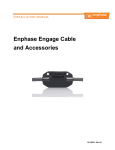
Enphase Engage Cable and
Accessories
Contact Information
Enphase Energy Inc.
201 1St Street
Petaluma, CA 94952
Phone: 707-763-4784 Toll Free: 877-797-4743
Fax: 707-763-0784
http://www.enphase.com
[email protected]
Other Information
Product information is subject to change without notice. All trademarks are
recognized as the property of their respective owners.
Copyright © 2011 Enphase Energy. All rights reserved.
Page 2
Copyright Enphase Energy Inc. 2011
141-00013 Rev 03b
Table of Contents
Important Safety Information .......................................................................... 5
Read this First ................................................................................................. 5
Safety Instructions ........................................................................................... 5
For Your Safety ............................................................................................. 5
Electrical Installation ..................................................................................... 5
The Enphase Engage Cable and Accessories ...................................................... 7
Compatibility ................................................................................................... 7
Parts and Tools Required ................................................................................... 7
Lightning Surge Protection ................................................................................ 7
Selecting Cable Type ........................................................................................ 8
Connector Spacing Options ............................................................................. 8
Voltage Types and Conductor Count ................................................................ 9
Racking Compatibility .................................................................................... 9
Cabling Length Options .................................................................................. 9
Planning for Cable Lengths and Type ................................................................ 10
Enphase Engage Cable and Accessories Installation .......................................... 11
Installation Procedure ..................................................................................... 12
Step 1 – Measure AC at Service Entrance Conductors ......................................... 12
Step 2 – Install the AC Branch Circuit Junction Box ............................................ 13
Step 3 – Position the Enphase Engage Cable...................................................... 14
Step 4 – Attach the Microinverters to the Racking .............................................. 14
Step 5 – Dress the Engage Cable ..................................................................... 15
Step 6 – Terminate the Unused End of the Engage Cable .................................... 17
Attaching the Terminator ............................................................................. 17
Replacing or Removing the Terminator .......................................................... 19
Step 7 – Connect the Engage Cable to Junction Box(es) ...................................... 19
Step 8 – Verification and Commissioning ........................................................... 21
Disconnecting a Microinverter from the Engage Cable ....................................... 22
Technical Data ............................................................................................. 23
Appendix – Sample Wiring Diagrams .............................................................. 25
Sample Wiring Diagram – 240 Vac ................................................................... 25
Sample Wiring Diagram – 208 Vac ................................................................... 26
Page 3
Copyright Enphase Energy Inc. 2011
141-00013 Rev 03b
Page 4
Copyright Enphase Energy Inc. 2011
141-00013 Rev 03b
Important Safety Information
Read this First
To reduce the risk of electrical shock, and to ensure the safe installation
and operation of the Enphase System, the following safety indications
appear throughout this document.
Indicates a hazardous situation, which if not avoided, will
result in death or serious injury.
Indicates a hazardous situation, which if not avoided, could
result in death or serious injury.
Indicates a hazardous situation which, if not avoided, could
result in minor or moderate injury.
Follow instructions closely to avoid damage or malfunction to
the device and/or damage to surrounding property.
Safety Instructions
For Your Safety
Risk of Electrical Shock. Do NOT connect or disconnect the
photovoltaic module from the Enphase Microinverter without
first removing AC power from the photovoltaic system.
Electrical Installation
Be aware that only trained solar professionals should install
and/or replace the Enphase Cabling System or connect the
Enphase Microinverter to the electrical utility grid.
Perform all electrical installations in accordance with all local
electrical codes and the National Electrical Code (NEC),
ANSI/NFPA 70.
The AC connectors on the cabling are rated as a disconnect
only when used with an Enphase Microinverter.
Connect the Enphase Microinverter to the electrical utility grid
only after receiving prior approval from the utility company
and any applicable AHJ (authority having jurisdiction).
Before installing the cabling, read all instructions and
cautionary markings in the user manual, on the Enphase
equipment, and on the all other photovoltaic equipment.
Page 5
Copyright Enphase Energy Inc. 2011
141-00013 Rev 03b
Page 6
Copyright Enphase Energy Inc. 2011
141-00013 Rev 03b
The Enphase Engage Cable and Accessories
The Engage Cable is a continuous length of 2.5 mm2 (12 AWG), outdoor rated
cable with integrated connectors for microinverters. These connectors are
preinstalled along the Engage Cable at intervals to accommodate PV module
widths. The microinverters plug directly into the cable connectors.
Compatibility
The cabling is compatible with a variety of PV racking systems. For a list of
approved PV racking systems, refer to the PV Racking Compatibility document on
the Enphase website (http://www.enphase.com/support/downloads).
Parts and Tools Required
In addition to the Enphase microinverters, PV modules, PV racking, and
associated hardware, you will need the following items.
Enphase equipment:
Enphase Engage Cable. See Selecting Cable Type on page 8 for options.
Watertight sealing caps, as needed (for any unused drops on the cable)
Terminators, as needed (for AC branch circuit cable ends)
Cable clips
Enphase disconnect tool (number 2 Phillips
screwdriver can be substituted)
Other items:
Outdoor-rated, weather-proof AC junction
box(es)
Grounding conductor
Torque wrench, sockets, wrenches for
mounting hardware
Adjustable wrench or open ended wrench (for terminators)
Lightning Surge Protection
Lightning protection and resulting voltage surge are protected in accordance with
EN 62305-1. It is assumed that the PV modules are installed in accordance with
related standards and that the microinverter is a part of a broader lightning
mitigation system in accordance with EN 62305-1, -3.
In some areas, the statistical frequency of lightning strikes near a PV installation
is high enough that lightning protection must be installed as part of an Enphase
system. In some areas, a surge protection device might be mandatory following a
risk analysis, according NFC 15-100 (art. 443) & NFC 15-443L.
Page 7
Copyright Enphase Energy Inc. 2011
141-00013 Rev 03b
Selecting Cable Type
Enphase Engage Cable is available in two different voltage types and two
connector spacing options. Depending upon installer needs, the cable is also
available in different lengths.
The cable is installed by simply rolling out
the desired length of cable and cutting it to
size. One end is wired directly into the
junction box at the head of the branch
circuit, eliminating the need for a separate
AC interconnect cable. The other end is
sealed from the environment using an
Enphase Branch Terminator. The
microinverter AC cable connectors are then
plugged into the regularly-spaced connectors
as shown.
Connector Spacing Options
The gap between connectors on the cable can be either 1.025 meters (40”) or 1.7
meters (67”). The 1.025 meter spacing is best suited for connecting PV modules
installed in portrait orientation, while the 1.7 meter gap is best suited to PV
modules installed in landscape orientation.
Page 8
Copyright Enphase Energy Inc. 2011
141-00013 Rev 03b
Voltage Types and Conductor Count
The voltage types are either 240VAC split phase or 208VAC three phase. All
cable connectors bear labels indicating their cable voltage designation.
Typically used for residential applications, 240VAC includes four conductors. This
cabling should also be used for split phase 208VAC applications. Three-phase
208VAC cabling includes five conductors, and is used for most commercial
installations. Because Enphase microinverters output onto two phases, three
phase cabling balances the phases by rotating conductor use from one
microinverter to the next as shown in the following diagram. In the diagram, the
three phases are labeled 1, 2, and 3.
Racking Compatibility
Engage Cabling is compatible with a variety of racking systems. For a list of
approved PV module racking types, refer to the Racking Compatibility document
at (http://www.enphase.com/support/downloads).
Cabling Length Options
Engage Cabling is available in shorter lengths with 30-40 connectors, depending
upon voltage type. Longer lengths can be ordered and cut to suit per order.
Ordering options include:
Model Number
Voltage type/
conductor #
Connector
count
Connector
spacing
PV module
orientation
Approx.
weight
ET10-240-40
240VAC,
4 conductor
40
1.025 m
(40”)
Portrait
18.1 kg
(40 lbs)
ET17-240-40
240VAC,
4 conductor
40
1.7 m (67”)
Landscape
20.4 kg
(45 lbs)
ET10-208-30
208VAC,
5 conductor
30
1.025 m
(40”)
Portrait
13.6 kg
(30 lbs)
ET17-208-30
208VAC, 5
conductor
30
1.7 m (67”)
Landscape
15.9 kg
(35 lbs)
ET10-240-BULK
240VAC,
4 conductor
240
1.025 m
(40”)
Portrait
over 90 kg
(200 lbs)
ET17-240-BULK
240VAC,
4 conductor
240
1.7 m (67”)
Landscape
over 90 kg
(200 lbs)
ET10-208-BULK
208VAC,
5 conductor
240
1.025 m
(40”)
Portrait
over 90 kg
(200 lbs)
ET17-208-BULK
208VAC,
5 conductor
240
1.7 m (67”)
Landscape
over 90 kg
(200 lbs)
Page 9
Copyright Enphase Energy Inc. 2011
141-00013 Rev 03b
Planning for Cable Lengths and Type
The Cabling System is flexible enough to adapt to almost any solar design. To
determine the length and cable type that you need, take into account the
following considerations:
The number of Enphase Microinverters to be installed on the AC
branch circuit. Be certain to allocate the correct number of connectors,
including extra connectors for gaps and turns.
Additional length required to reach from the AC branch circuit
junction box to the first microinverter. If greater than half a connector
interval is needed, it may be necessary to allow for one (or more) unused
connectors in order to span this distance. Unused connectors must be covered
with Enphase watertight sealing caps.
Additional length required to reach from one row of PV modules to the
next. If the PV modules are laid out in multiple rows, the distance from one
row to the next often requires additional cabling length.
Bend radius. When planning cabling turns or loops, you must account for a
minimum bend radius of 6.7 cm (2.625”).
Multiple sub-arrays. Often, the AC branch circuit may be composed of
several smaller sub-arrays across more than one roof plane. In this case, the
cable is cut to service each smaller array, and the sub-arrays are connected
together using appropriately rated lengths of conduit. The transition from
cable to conduit is accomplished using an outdoor rated AC junction box, as
required by the NEC and local code. Unused connectors must be covered with
Enphase watertight sealing caps.
Mixture of PV modules in both portrait and landscape orientation.
When PV modules are installed in mixed orientation (both portrait and
landscape orientation), there are three choices for cabling:
1. Cabling with 1.025 meter spacing between connectors results in cleanest
install for the PV modules in portrait orientation. For PV modules placed in
landscape orientation, plan for an unused connector between each PV
module to accommodate the required additional distance. Unused
connectors must be covered with Enphase watertight sealing caps.
2. Cabling with 1.7 meter spacing between connectors results in cleanest
install for PV modules in landscape orientation, but requires that any
additional cable length between PV modules in portrait orientation be
coiled and dressed so that cabling does not contact the roof. Again,
unused connectors must be covered with Enphase watertight sealing caps.
3. Another solution when PV modules are installed in mixed orientation is to
transition between 1.025 and 1.7 meter spacing cable options using an
outdoor rated junction box. This junction box can be installed to the PV
racking.
Page 10
Copyright Enphase Energy Inc. 2011
141-00013 Rev 03b
Enphase Engage Cable and Accessories
Installation
Follow the instructions in this section to install the Engage Cable.
For information on microinverter installation, refer to the M215 Installation and
Operation Manual at http://www.enphase.com/support/downloads.
Page 11
Copyright Enphase Energy Inc. 2011
141-00013 Rev 03b
Installation Procedure
Installing the Engage Cable and Accessories involves several key steps:
1. Measure AC at Service Entrance Conductors
2. Install the AC Branch Circuit Junction Box
3. Position the Engage Cable
4. Attach the Microinverters to the Racking
5. Dress the Engage Cable
6. Terminate the Unused End of the Engage Cable
7. Connect the Engage Cable to Junction Box(es)
8. Verification and Commissioning
Risk of Electrical Shock. Due to presence of exposed
conductors, DO NOT connect the Enphase Microinverters to
the utility grid or energize the AC circuit(s) until you have
completed all of the installation procedures as described in
the following sections.
Step 1 – Measure AC at Service Entrance Conductors
Measure AC line voltage at the service entrance conductors. Acceptable ranges
are shown in the following table.
240 Volt AC Split Phase
208 Volt AC 3 Phase
L1 to L2
211 to 264 Vac
L1 to L2 to L3
183 to 229 Vac
L1, L2 to neutral
106 to 132 Vac
L1, L2, L3 to neutral
106 to 132 Vac
Be sure the Engage Cable you are using matches the service
at the site. Use 208Vac cabling at sites with three-phase
208Vac service, or use 240Vac cabling at sites with 240Vac
service. Check the labeling on the cable drop connectors to
verify the cable type.
Page 12
Copyright Enphase Energy Inc. 2011
141-00013 Rev 03b
Step 2 – Install the AC Branch Circuit Junction Box
Risk of Electrical Shock. Be aware that installation of this
equipment includes risk of electric shock. Do not install the
junction box without first removing AC power from the
Enphase System.
Use electrical system components approved for wet locations
only.
When stripping off the cable sheath, make sure that the
conductors are not damaged.
Do not weigh down the cabling system.
Loose cables might become a tripping hazard. Attach the
power cables correctly.
Do NOT exceed the maximum number of microinverters in an
AC branch circuit as listed on page 7 of this manual, and
protect each microinverter AC branch circuit with a 20 A
maximum breaker.
a. Size the AC wire gauge to account for voltage drop. Select the correct
wire size based on the distance from the beginning of the microinverter
branch circuit to the breaker in the load center.
All components of system wiring must be considered, including internal
voltage drop within the length of Engage Cable. Typically, three wire
sections and several wire terminations must be quantified. There is
also some resistance associated with each OCPD (OverCurrent
Protective Device), typically a circuit breaker. As all of these
resistances are in series, they add together. Since the same current is
flowing through each resistance, the total voltage drop is total current
times the total resistance. For a split-phase system, the total
resistance is equal to two times the one-way resistance. For a threephase system, each of the three line currents and resistances must be
calculated.
NEC guidelines for voltage drop on feeder and branch circuit
conductors will not be sufficient for microinverter branch
circuits that contain the maximum allowable microinverters.
This is due to high inherent voltage rise on the branch circuit.
For more information, refer to the Voltage Drop Calculations Application
Note at http://www.enphase.com/support/downloads.
b. Install an outdoor rated, weather-proof junction box at a suitable
location on the PV racking system (typically at the end of a row of
modules).
c. Provide an AC connection from the junction box back to the utility
interconnection, using equipment and practice as required by the NEC
and local jurisdictions.
Page 13
Copyright Enphase Energy Inc. 2011
141-00013 Rev 03b
Step 3 – Position the Enphase Engage Cable
Many modules have a central stiffening brace. In these cases,
do not position the connector and microinverter at the exact
center of the PV module, but position the cable so that
connectors do not conflict with the braces.
a. Lay the cabling along the route it will travel, positioning the connectors
so that they align with the PV modules.
b. Module widths vary by manufacturer. On the Engage Cable, connectors
are spaced at intervals to allow for the widest PV modules compatible
with Enphase Microinverters. If narrower modules are used, it may be
necessary to account for excess cable by adding a loop of cable at
suitable intervals.
Step 4 – Attach the Microinverters to the Racking
a. Mount the microinverters according to the microinverter
manual. Ensure both that the microinverter does not interfere with the
PV module frames or stiffening brace, and that the drop cable from the
microinverter can easily reach the connector on the cable.
b. Ground the microinverters using either a continuous, unbroken
grounding conductor or approved grounding washers. Follow the
methods described in the M215 Installation and Operation Manual at
http://www.enphase.com/support/downloads.
Page 14
Copyright Enphase Energy Inc. 2011
141-00013 Rev 03b
Step 5 – Dress the Engage Cable
Adhere to the following requirements:
Do not expose the connection to directed, pressurized liquid (water
jets, etc.).
Do not expose the connection to continuous immersion.
Do not expose the AC connector to
continuous tension (e.g., tension due to
pulling or bending the cable near the
connection)
Use only the connectors and cables provided.
Do not allow contamination or debris in the
connectors.
Use the cable and connectors only when all
parts are present and intact.
Fit the connection using only the prescribed
tools.
There are two release holes in the cable
connector. These holes are used to disconnect the connector. Keep
these release holes clear and accessible.
a. Attach the Engage Cable to the rack using the
included clips, or you may use tie wraps.
The cable clips are designed so that the drop
cable from the microinverter can also be
dressed into the clip underneath the cable.
b. Dress any excess cabling in loops so that
cabling does not contact the roof.
Tripping Hazard. Do not leave the cabling to rest on the
roof. Loose cables might become a tripping hazard. Attach the
power cables correctly.
c. Place tie wraps or clips on either side of the drop connector. Use one or
two additional clips, tie wraps, or other support scheme to secure the
cable between connectors.
d. Remove the temporary shipping cap from the Engage Cable.
Page 15
Copyright Enphase Energy Inc. 2011
141-00013 Rev 03b
Step 5 – Dress the Engage Cable (continued)
e. Connect the microinverter and listen for two
clicks as the two prongs engage. Ensure that
both latching mechanisms have engaged.
The connector has not been
designed for repeated linking
and unlinking.
f.
Repeat steps a through e for all microinverters
in the branch.
g. Cover any unused connector with a watertight
sealing cap. Listen for two clicks as the connectors
engage. Ensure that both latching mechanisms
have engaged.
Make sure watertight sealing
caps are installed on all unused
AC connectors. Unused AC
connectors are live when the system is energized by
the utility.
Do not use the shipping cap to cover unused
connectors. The shipping cap does not provide an
adequate environmental seal. Enphase watertight
sealing caps (included in the Installation Kit) are
required for protection against moisture ingress.
Enphase watertight sealing caps are IP67 rated.
Within the term “IP67”, “IP” indicates an Ingress
Protection (IP) rating against dust and liquids. This
specific rating of IP67 indicates that this connector
protects against all dust particles and immersion in
liquid.
If you need to remove a watertight sealing cap, you
must use the Enphase disconnect tool or a #2 Phillips
screwdriver.
Page 16
Copyright Enphase Energy Inc. 2011
141-00013 Rev 03b
Step 6 – Terminate the Unused End of the Engage Cable
Attaching the Terminator
The terminator is intended for one-time use only. If you open
the terminator following installation, the latching mechanism
is destroyed and the terminator cap cannot be used again. If
the latching mechanism is defective, the terminator must not be used. The
latching mechanism must not be circumvented or manipulated.
Adhere to the following requirements:
Use of the terminator assembly is the only method allowed to seal the
conductor end of the trunk.
Do not expose the terminator cap to directed, pressurized liquid (water
jets, etc.).
Do not expose the terminator cap to continuous immersion.
Do not expose the terminator cap to continuous tension (e.g., tension
due to pulling or bending the cable near the terminator cap)
Do not install or use in potentially explosive environments.
Do not allow the terminator to come into contact with open flame.
Use the terminator cap assembly only when all parts are present and
intact.
Fit the terminator cap using only the prescribed tools.
To attach the terminator:
a. Check the terminator cap assembly for completeness. It is made up of the
individual parts shown.
Hex nut
Wire organizer
Cap
Cable seal
b. To guarantee the safety of the wire
organizer and to ensure that it remains
sealed, please make sure that all parts are
present and that all seals are seated
correctly in the wire organizer.
O-ring
The wire organizer must be complete, as shown.
Risk of Electrical Shock. The terminator cap must not be
installed while power is connected.
Page 17
Copyright Enphase Energy Inc. 2011
141-00013 Rev 03b
c. Strip at least 60 mm (2.5 inches) of the shielding
from the conductors.
If the exposed wires are damaged,
system function can no longer be
guaranteed.
d. Slide the hex nut onto the cable.
e. Insert the cable all the way into the wire organizer (up to the stop).
f.
Bend the individual wires into the slots (spaces) on
the wire organizer.
g. Using a diagonal cutter, trim wires to the correct
length so that they fit cleanly into the slots
(spaces) in the wire organizer.
h. Press the cap onto the wire organizer,
bending the wires into the slots of the wire
organizer.
If the wires resist being pressed into the cap, you
may need to trim the wires a little further using a
diagonal cutter.
i.
Screw the hex nut onto the cap.
Never unscrew the hex nut as this can
twist and damage the cable.
j.
Insert a #2 Philips screwdriver into the slot on the
cap to hold it in place. (Alternatively you can hold
the cap firmly in place using the Enphase hand
tool).
k. Use a 24mm (7/8 inch) wrench and tighten the nut
until the latching mechanism has been screwed all
the way to the base.
l.
Page 18
Use a tie wrap or cable clip to attach the cable to the racking, so that the
cable and terminator do not touch the roof.
Copyright Enphase Energy Inc. 2011
141-00013 Rev 03b
Replacing or Removing the Terminator
If the terminator must be replaced or removed, observe the following.
Risk of Electrical Shock. Never open, remove or replace the
terminator while it is connected to the power supply.
Damage to the latching mechanism cannot be seen with the
naked eye. Label the opened terminator and dispose of it
immediately to ensure that it cannot be reused accidentally.
The terminator is intended for one-time use only.
If you open the terminator again following the installation,
this will destroy the latching mechanism, meaning that the
unit then cannot be used again.
a. Remove the terminator by cutting it off using a diagonal cutter set flush
against the end of the cable.
b. Replace the terminator as described in the previous steps, beginning on page
17.
Step 7 – Connect the Engage Cable to Junction Box(es)
Perform the following steps in accordance with NEC
regulations.
a. Connect Engage Cable into the AC branch circuit junction box using an
appropriate gland or strain
relief fitting. The cable
requires a strain relief
connector with an opening of
1.3 cm (0.5 inches) in
diameter.
b. Connect the Engage Cable
into additional junction boxes
as needed to transition to
conduit between smaller subarrays. Remember to adhere
to branch limits for the
microinverters being used.
Page 19
Copyright Enphase Energy Inc. 2011
141-00013 Rev 03b
Refer to the wiring diagrams located in the Appendix of this manual for more
information.
The Engage Cable uses a different wiring scheme than used
with other Enphase Microinverters. Be aware of the difference
in wire color code.
The 12 AWG conductors are identified as follows: L1 is sheathed in Black, L2 is
sheathed in red, L3 is sheathed in blue (208 Vac only), Neutral is sheathed in
white, and Ground is sheathed in green. The grounding wire is used to ground the
microinverters. A WEEB or continuous ground is required in addition to this green
grounding wire.
Balanced 208 VAC is accomplished by alternating phases between microinverters.
240 Volt AC Split Phase Wiring
208 Volt AC Three-Phase Wiring
Black – L1
Red – L2
White – Neutral
Green - Ground
Black – L1
Red – L2
Blue – L3
White – Neutral
Green - Ground
The green wire acts as equipment ground. A continuous GEC for system ground is
also required as described in the next step.
Page 20
Copyright Enphase Energy Inc. 2011
141-00013 Rev 03b
Step 8 – Verification and Commissioning
Prior to final connection to the utility grid, ensure that
all AC and DC wiring is correct.
a. Ensure that none of the AC and DC wires are pinched or damaged.
b. Ensure that all junction boxes are properly closed.
c. Ensure that all unused connectors are capped.
d. Ensure that all connectors are properly seated.
e. Install the microinverters and commission the system as instructed
by the Enphase Microinverter installation and operation manual.
Page 21
Copyright Enphase Energy Inc. 2011
141-00013 Rev 03b
Disconnecting a Microinverter from the Engage
Cable
To ensure the microinverter is not disconnected from the PV modules under load,
adhere to the following disconnection steps in the order shown:
1. Disconnect the microinverter AC connector from the Engage Cable.
2. Cover the module with an opaque cover.
3. Using a DC current probe, verify there is no current flowing in the DC
wires between the PV module and the microinverter.
Care should be taken when measuring DC currents due to the
fact that most clamp-on meters must be zeroed first and tend
to drift with time.
4. Disconnect the PV module DC wire connectors from the microinverter.
5. Remove the microinverter from the PV array
racking.
6. The microinverter connectors are toolremovable only. The installation kit includes
a disconnect tool with two prongs. To
disconnect a microinverter from the cabling
system, insert these two prongs into the two
holes in the cable connector. Squeeze the
sides of the disconnect tool to engage with
the connector. Rock the connector back and forth while pulling gently
to disengage.
7. If the disconnect tool is not available, a #2 Phillips screwdriver can be
used in its place. Insert the screwdriver into one hole, rock that side of
the drop connector out, then insert the screwdriver into the other hole
and pull the connector out entirely.
Risk of Electrical Shock. Do not leave the drop connector
uncovered for an extended period. If you do not plan to
replace the microinverter immediately, you must cover any
unused connector with a watertight sealing cap. Listen for two
clicks as the connectors engage.
Page 22
Copyright Enphase Energy Inc. 2011
141-00013 Rev 03b
Technical Data
Specification
Value
System temperature range (ambient)
-40C to +65C (-40F to 149F)
Cable temperature rating
90C Dry / 90C Wet
Cable insulator rating
THWN-2
Environmental protection rating
IEC 60529 IP67
UV exposure rating
UL 746 C, F1
Conductor gauge
12AWG
Maximum current carrying capacity of the
Engage Cable
20 amperes
Maximum current carrying capacity of the drop
cable (on the microinverter)
4 amperes
Cable bundle diameter
1.3 cm (0.525”)
Drop connector dimensions
11.8 cm x 6.0 cm x 3.2 cm
(4.64” x 2.36” x 1.25”)
Terminator cap dimensions
3.6 cm diameter x 5.1 cm tall
(1.4” x 2”)
Cable weights [about 1lb (0.5 kg) per drop]:
30-drop cable
30 lbs/14 kg (approximate)
40-drop cable
40 lbs/18 kg (approximate)
240-drop cable
Page 23
240 lbs/110 kg (approximate)
Copyright Enphase Energy Inc. 2011
141-00013 Rev 03b
Page 24
Copyright Enphase Energy Inc. 2011
141-00013 Rev 03b
Appendix – Sample Wiring Diagrams
Sample Wiring Diagram – 240 Vac
Page 25
Copyright Enphase Energy Inc. 2011
141-00013 Rev 03b
Sample Wiring Diagram – 208 Vac
Page 26
Copyright Enphase Energy Inc. 2011
141-00013 Rev 03b
Enphase Energy Inc.
201 1St Street
Petaluma, CA 94952
Phone: 707-763-4784
TOLL FREE: 877-797-4743
Fax: 707-763-0784
www.enphase.com
[email protected]