1
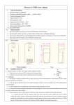
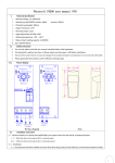
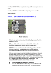
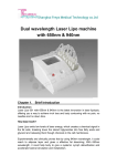
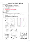
Photocell beam sensor and flash lamp User Manual (PF5103)
I. Technical Specification
1. Working voltage: 12~24VAC/DC
2. Working current(24VDC):emitter: ≤15mA receiver: ≤30mA
3. Photocell wavelength: 940nm
4. Angle of opposite emission: ≤±5º
5. Receiver range: ≥12m
6. Working temperature: -20º~+60℃
7. Relay contact loading capacity: 1A/30VDC
8. Waterproof grade: IP54
9. Can connect external flash lamp signal (12V-24VAC/DC), LED can flashing.
10. Size: 127*50*35mm
II. Safety Instruction
1. For security, please read the user manual carefully before initial operation;
2. This photocell is without any fuse, so Please make sure the power is off before installation;
3. Only used this system that do not cause any danger life or property during the running
failure or its security risks eliminated;
4. Please guarantee the products used in effective working range.
III. Picture Display
IV. Installation instruction
1. The product should be installed more than 20cm upper the ground(to avoid reflection), and the distance between emitter and receiver
shall be more than 0.5 meters(if not , maybe the photocell will working on or cannot work);
2. the end user should installed the photocell on the back of the direct sunshine or other strong shining(±5º) to keep the photocell work
well steadily
3. Pls try to avoid installing other photocell emitters within effective receive range;
4. If install many photo cells on the same line, can install receivers on two ends and then emitters in the middle back to back which can
effectively avoid the problem as above.
5. in order to avoid signal bias of emitters and receivers which will easily cause mis-operation, pls Installate the photocell firmly
6. Connecting power after checking no error of connecting lines:
6.1 Photocell
After the emitter and receiver module of photocell input 12V-24VAC/DC, emitter LED on,receiver LED on, receiver NO/COM on while
NC/COM off;
Making the CAP of emitter and receiver align, receiver LED off, NC/COM on while NO/COM off. If the signal between emitter and receiver is
interrupted, receiver LED on, NC/COM off while NO/COM on.
6.2 Flash lamp
6.2.1 When there is signal income from FLASH port(12V-24V AC/DC)
It keeps lighting when JP1 CAP connects the two pins under
It blinks when JP1 CAP connects the two pins upper
6.2.2 When there is no signal income from FLASH port(12V-24V AC/DC)
It doesn't work when JP1 CAP connects any two pins
V Installation Pictures
1. Open package
5. Fix bottom
2. Fix the holder
location map on
6. Put top cover
3. Drill, and fix
expansion sleeve.
4. Connect
wires
7. Screw bottom and
top cover together
8. Finished