1
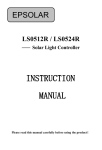
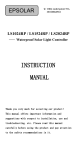
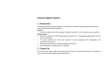
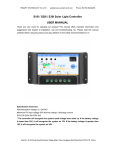
EPSOLAR Solar Charge Controller & LED Driver USER MANUAL Thank you very much for selecting our product! This manual offers important information and suggestions with respect to installation, use and troubleshooting, etc. Please read this manual carefully before using the product and pay attention to the safety recommendations in it. LandStar Solar Charge Controller & LED Driver Nominal system voltage 12/24VDC* Maximum PV input voltage 50V Nominal charge current: LS102460BPLD 10A LS2024100BPLD 20A Nominal output power / output current: LS102460BPLD 30W/12V 60W/24V 2.0A LS2024100BPLD 50W/12V 100W/24V 3.3A *The solar charge controller has the automatic recognized 12/24VDC system voltage function. Most of parameters about discharge and LED load control could be modified. Warranty: The controller is warranted to be free from defects for a period of two (2) years from the date of shipment to the original end user. Notice: Manufacture is not responsible for the damage of any part of controller due to operator's misuse, battery parameters mismatch, unreasonable system configuration, unauthorized repair or exceeding the specified parameters. Contents 1 Important Safety Information .....................................1 2 General Information ...................................................1 3 Installation Instructions ..............................................2 3.1 General Installation Notes ................................2 3.2 Wiring ..............................................................3 4 Operation....................................................................4 5 Setting Operation........................................................5 6 Protection and Troubleshooting ..................................8 6.1 Protection .........................................................8 6.2 Troubleshooting ...............................................9 7 Technical Specifications ...........................................11 Annex: Mechanical dimensions ...................................13 1 Important Safety Information Please inspect the controller thoroughly after it is delivered. If any damage is seen, please notify the shipping company or our company immediately. 2 General Information LandStarBPLD series solar charge controller combines the solar charge controller and LED constant current driver into one unit which is ideal for solar LED lighting, especially for the application for LED lamp which requires dimmer function, road lighting, cityscape lighting and advertising lighting. It has some excellent feathers including the high efficiency and accuracy, small size, potting waterproof and editable load control parameters. 12/24VDC automatic recognized system voltage. Optional battery type among Gel, Sealed (default) and Flooded. Wide battery voltage range: 8VDC ~ 32VDC, compatible with 12/24VDC full voltage range. Digital precision constant current control and the control accuracy better than 10mA. Maximum output efficiency is above 97%. The output current can be adjusted among the rated power and current range. LandStarBPLD has one key and two segment numerical LED displays (LED1 and LED2). The discharging control parameters and the control mode of the load can be modified by the key; meanwhile LED displays running information of system. Electronic protection: overheating, reversed polarity protection and load short circuit, etc. 1 Load control parameter and output current value can be set separately. IP67 protection. 3 Installation Instructions 3.1 General Installation Notes Be very careful when working with batteries. Wear eye protection. Have fresh water available to wash and clean any contact with battery acid. Never short the battery positive and negative terminals and wires which may cause explosion or fire. Install external fuses/breakers as required. Disconnect the solar module and fuses/breakers near to battery before installing or adjusting the controller. Confirm that power connections are tightened to avoid excessive heating from loose connection. Uses insulated tools and avoid placing metal objects near the batteries. Loose power connections and/or corroded wires may result in resistive connections that may melt wire insulation, burn surrounding materials, or even cause fire. Ensure tight connections and use cable clamps to secure cables and prevent them from swaying in mobile applications. Only Gel, Sealed and Flooded type batteries can be charged. Battery connection may be wired to one battery or a bank of batteries. The following instructions refer to a singular battery, but it is implied that the battery connection can be made to either one battery or a group of batteries in a battery bank. 2 3.2 Wiring 1. Connect components to the charge controller in the sequence as shown in above picture and pay much attention to the “+”(Red) and “-”(Black). Always power the battery First. 2. After power the battery, check the battery indicator on the controller, it will be green. If it’s not green, please refer to chapter 6. 3. The battery fuses should be installed as close to battery as possible and it suggests that the distance is less than 150mm. 3 4 Operation Indicator Status Description Green On solid Normal Green Slowly flashing In charging Green OFF No charge Green On solid Green Slowly flashing Normal Full Green Fast flashing Over voltage Orange On solid Under voltage Red On solid Over discharged Red Flashing Battery overheating Charging and battery indicator (red) System voltage error flashing simultaneously Charging and battery indicator(orange) Controller overheating flashing simultaneously 4 5 Setting Operation LED1 LED2 Key LED1 is used to show parameter, LED2 is used to show corresponding setting value. LEDs are used to show error code. The parameters of controller can be set via the key, and the setting method is shown as follow: (1) The LEDs are off after powering on the controller. When LEDs are in OFF state, pressing the key can switch on or off the load only when the load mode is “Output mode 1”. (2) Press the key and hold on 5 seconds to enter control mode menu with LEDs on. Press the key to roll the item in circle. (3) Press the key to roll the item in the control mode menu and hold on 5 seconds to enter edit mode with the LED2 flashing. Add the value by pressing the key. Save the data and return to the menu with no operation over 5 seconds. (4) LEDs will be OFF with no operation over 10 seconds. The reference of LED for parameter and setting value is shown in the table. Item LED1 LED2 Default Range Content 1 Battery type 1 1-3 1: Sealed 2: Gel 3: Flooded 2 LVD 8 0-4. 10.6V-12.0V accuracy0.1V(x2/24V) 5 3 Load set 0 0-4 0:Light ON 1:Light ON +Time mode 2:Output mode1 3:Output mode2 4:Test mode 4 Light ON/OFF threshold voltage 5 1-7. 1-17V(x2/24V) 5 Light ON +Time mode1:TIME1 5 0-4. 0-14H, accuracy 1H 6 Light ON +Time mode2:TIME2 5 0-4. 0-14H, accuracy 1H 7 Light ON +Time mode3:TIME3 1 0-4. 0-14H, accuracy 1H 1. Number of LED parallel group 1 1-0. 1-10 groups 2. Light ON+ Time mode select 1 1-2 Mode1 Mode2 3. TIME1 percent 0. 0-0. 0%-100% ,accuracy 10% 4. TIME2 percent 5 0-0. 0%-100% ,accuracy 10% 5. TIME3 percent 0 0-0. 0%-100% ,accuracy 10% 0. Single LED string current 3. 0-9. 200-390mA,accuracy10mA (Default: 330mA) Note: 1. Radix point of LED segment display indicate the value added “10”, for example 0.=10,4.=14. 2. Test Mode is as same as Light Control Mode but no delay. Therefore, test mode is only used to test load switch. No operation will automatically exit, it can return to the previous mode within 120 seconds. 3. Low Voltage Reconnect Voltage =Low Voltage Disconnect Voltage+0.5V/12V(x2/24V). 4. Output mode1:The key is enabled. Output mode 2:The key is disabled. 5. It can be set the Day Time Threshold Voltage (DTTV) and Night Time Threshold Voltage (NTTV), DTTV equal to NTTV. 6. LED Total current=Number of LED parallel group×Single 6 LED string current. Note:If the total load current exceeds the rated current, the system will work with the rated current. 7. Mode 1 Mode 2 The reference of LED for error code is shown in the table Fault and warning code E1 Detail of fault, warning, working state code Fully protected against battery over discharged and voltage is lower over discharge point E2 Fully protected against battery over discharged and voltage is lower over discharge point without getting to back point E3 Load over load E4 Load short circuit E5 Open load “.” (radix point) The radix point of LED1 lighting up indicates that load is open. Oppositely, load is closed 7 If fault and working state on left appear, corresponding code will be displayed. Several states occur at the same time, these code will be displayed circularly (interval 1s). Only one state occurs, the code flashes per 1s. You can enter setting mode and set parameters despite the error shows Load state (radix point) will conceal during fault displaying and parameter setting 6 Protection and Troubleshooting 6.1 Protection PV Array Short Circuit If PV array short circuit occurs, clear it to resume normal charge automatically. Load Overload If the load current exceeds the rated output current of controller(≥1.05 times rated discharge current), the controller will disconnect the load. Once the overload occurs, the way to solve is to press the key to clear error or reset the controller after reducing the load. Load Short Circuit Fully protected against load wiring short-circuit (≥2 times rated output current). After five automatic load reconnect attempts, the fault must be cleared by pressing the key or restarting the controller. PV Reverse Polarity Fully protection against PV reverse polarity, no damage to the controller will result. Correct the miswire to resume normal operation. Battery Reverse Polarity Fully protection against battery reverse polarity, no damage to the controller will result. Correct the miswire to resume normal operation. Battery working voltage error If battery voltage does not match controller working voltage, controller will stop working. After correcting the voltage, the fault must be cleared by restarting the controller. Damaged Local Temperature Sensor 8 If the temperature sensor short-circuited or damaged, the controller will be charging or discharging at the default temperature 25C to prevent the battery damaged from overcharging or over discharged. Overheating Protection If the temperature of the controller heat sink exceeds 85C, the controller will automatically start the overheating protection and stop the charging and discharging. When the temperature is below 75C, the controller will resume to work. High Voltage Transients PV is protected against small high voltage surge. In lightning prone areas, additional external suppression is recommended. Note: The controller has daily automatic fault clear function which will reduce the manual operation and can intelligently eliminate the fault caused by non-actual hardware failure. 6.2 Troubleshooting Faults Possible reasons Troubleshooting Charging LED indicator off Check that PV and battery wire during daytime PV array when sunshine disconnection connections are correct and tight falls on PV modules properly Battery voltage Green battery higher than over LED indicator voltage fast flashing disconnect Check the battery voltage. If it over high, disconnect the solar module immediately and change a new controller voltage(OVD) Load output is normal. Battery Battery LED Battery under indicators orange voltage Battery LED Battery LED indicator will return to green automatically when fully charged The controller cut off the output 9 indicators red over discharged color and loads automatically. LED indicator will return to green not working automatically when fully charged Remove or cut out the additional load. Press the key to Over load clear error and the controller will resume to work after 3s or Load abnormal restart the controller shutdown Clear short circuit. Press the key to clear error and the controller Short circuit will resume to work after 3s or restart the controller When heat sink of the controller exceeds 85C, the controller All the led will automatically cut input and indicator flashing Too high (battery orange temperature of output circuit. When the indicator controller temperature below 75C, the controller will resume to work. flashing) Please reduce the environment temperature, the power of solar module or the power of the load Check whether the battery All the led voltage match with the indicator flashing (battery red System voltage controller working voltage. error Please change to a suitable indicator battery or reset the working flashing) voltage 10 7 Technical Specifications Electrical parameters LS******BPLD Nominal system voltage Max. PV input voltage Battery terminal voltage Rated charge current Rated output power Rated output Current 102460 50V 8 ~ 32V 10A 20A 30W/12V 60W/24V 50W/12V100W/24V 2.0A 3.3A 96% 97% Max efficiency Output voltage range Load open circuit voltage Power output adjustment time Self-consumption 2024100 12/24VDC Voltage of battery+2V ~ 60V 60V <5s 9.4mA/12V;12.2mA/24V 8mA/12V;7mA/24V Control accuracy 10mA Temperature compensation coefficient -3mV/C/2V(25C) Battery Voltage Parameters (parameters is in 12V system at 25C, please use double value in 24V system) Battery charging Sealed setting item Over Voltage 16V Disconnect Voltage Charging Limit 15V Voltage Over Voltage Reconnect Voltage Equalize Charging Voltage Boost Charging Voltage Float Charging Voltage Boost Reconnect Charging Voltage Gel Flooded 16V 16V 15V 15V 15V 15V 15V 14.6V —— 14.8V 14.4V 14.2V 14.6V 13.8V 13.8V 13.8V 13.2V 13.2V 13.2V 11 Low Voltage Reconnect Voltage Under Voltage Warning Reconnect Voltage Under Voltage Warning Voltage Low Voltage Disconnect Voltage Discharging Limit Voltage Equalize Duration Boost Duration 11.9V 11.9V 11.9V 12.2V 12.2V 12.2V 12V 12V 12V 11.4V 11.4V 11.4V 10.6V 10.6V 10.6V 2 hours 2 hours —— 2 hours 2 hours 2 hours Notes: The default battery type is Sealed. For Gel, Sealed, Flooded battery type, the voltage point is fixed, unable to modify it. *Please carefully to select battery type. It will damage battery if the setting is incorrect. Environmental parameters Environmental parameters Parameter Working temperature -35C ~ +55C Storage temperature -35C ~ +80C Enclosure IP67 LS102460BPLD mechanical parameters Mechanical parameter Parameter Overall dimension 108.5x75x25.6mm Mounting dimension 100.5 mm Φ5 Mounting hole size Power cable 4mm2(PV/ Batt.)1.0mm2(Load) Net weight 0.36 kg LS2024100BPLD mechanical parameters Mechanical parameter Parameter Overall dimension 108.5x110x25.6 mm Mounting dimension 100.5*70 mm Mounting hole size Φ5 Power cable 6mm2(PV/Batt.)1.5mm2(Load) Net weight 0.5 kg 12 Annex: Mechanical dimensions LS102460BPLD Dimensions (mm) 13 LS2024100BPLD Dimensions (mm) Final interpretation right of the manual belongs to our company. Any changes without prior notice! Version number: 14 V1.5 BEIJING EPSOLAR TECHNOLOGY CO., LTD Tel: +86-10-82894112 / 82894962 Fax: +86-10-82894882 E-mail: [email protected] Website: http://www.epsolarpv.com/