1
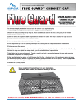
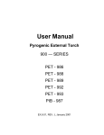
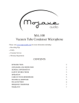
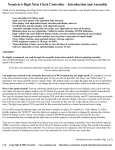
User Manual
Manual/Semi-automatic
CV — Tool
CV.6.01, Rev. C, May 1997
Thank you for purchasing Persys Manual/Semi-automatic CV—Tool.
This manual has been written to provide all relevant instructions for installing, operating
and maintaining your CV—Tool. We recommend you read these instructions before
attempting to install or operate your CV—Tool to ensure the maximum service life of your
equipment.
Persys Technology Ltd. believes the information contained in this publication is accurate
as of its latest printing date, and reserves the right to make changes in specification and
information without prior notice. Persys is not responsible for any inadvertent errors.
The terms and conditions governing the sales of Persys products and the licensing and
use of software consist solely of those set forth in the contracts between Persys and its
customers. No representation or other affirmation of fact contained in this publication,
including but not limited to statements regarding capacity, response time performance,
suitability for use or performance of products described herein shall be deemed to be a
warranty by Persys for any purpose or give rise to any liability by Persys whatsoever.
In no event shall Persys be liable for any incidental, indirect, special or consequential
damages whatsoever (including but not limited to loss of profits) arising out of or relating
to this publication or the information contained in it, even if Persys has been advised ,
knew or should have known of the possibility of such damages.
The products described in this document are confidential and propriety of Persys or its
licensors.
No part of this document may be reproduced in any form, including by electronic
retrieval systems, without prior written permission of Persys.
Copyright 1993 by Persys Technology Ltd., (Persys).
All rights reserved
TABLE OF CONTENTS
1.0
2.0
3.0
INTRODUCTION
1
1.1
Scope of the Manual
1
1.2
Description
1
1.2.1
Overview
1
1.2.2
Manual CV—Tool
1
1.2.3
Semi-automatic CV—Tool
2
TECHNICAL DATA
3
2.1
CV—Mask and Clips
3
2.2
Manual CV—Tool
4
2.3
Semi-automatic CV—Tool
4
INSTALLATION AND OPERATION
5
3.1
Unpacking
5
3.1.1
CV—Masks
5
3.1.2
Manual CV—Tool
5
3.1.3
Semi-automatic CV—Tool
5
3.2
3.3
Installation
5
3.2.1
Manual CV—Tool
5
3.2.2
Semi-automatic CV—Tool
5
Operation
6
3.3.1
Manual Tool
6
Positioning Mask
6
Removing Mask after Sputtering
8
3.3.2
Semi-automatic Tool
11
Positioning Mask
10
Removing Mask after Sputtering
12
4.0
CALIBRATION – Semi-automatic CV—Tool
16
4.1
Preliminary Steps
16
4.2
Cassette Base Adjustment
17
4.3
Pushing Fork Alignment
17
4.4
Pushing System Stoppers Adjustment
18
4.4.1
Pushing System Backward Motion
18
4.4.2
Pushing System Forward Motion
19
4.5
5.0
6.0
Teflon Base Stoppers Adjustment
19
MAINTENANCE
20
5.1
Semi-automatic CV—Tool
20
SPARE PARTS AND ACCESSORIES
21
LIST OF ILLUSTRATIONS
Figure
Title
Page
1—1
Manual CV—Tool
1
1—2
Semi-automatic CV—Tool
2
4—1
Semi-automatic CV—Tool, Side & Top View
16
Principle Changes in Present Revision (C)
1.
The 8” CV tool is presented in this revision. Specifications, operation and spare
parts sections are revised accordingly.
2.
Several drawings are revised in the operation chapter to present a more accurate
view of the CV tool.
1.0
INTRODUCTION
1.1
Scope of the Manual
This manual provides the installation, operation and maintenance procedures of the CV
Manual and Semi-automatic Tools.
1.2
Description
1.2.1
Overview
The CV—Mask is an aluminum mask with specially shaped holes. It is attached to the
wafer with Stainless Steel clips by means of a CV—Tool.
The wafer/mask/clips assembly travels through semi-automatic transfer machines in the
same way as the regular process wafer.
Disposable one-time-use ensures a constant and well-shaped dot size of 0.8mm, 1.2mm
or 1.6mm.
1.2.2
Manual CV—Tool (Fig. 1–1)
The Manual CV—Tool consists of a wafer shaped Teflon base and an anodized
Aluminum cover with a Teflon butterfly. Its purpose is holding the wafer in position
while attaching the four Stainless Steel clips.
Figure 1 — 1 Manual CV—Tool
Manual/Semi-automatic CV—Tool
1
1.2.3
Semi-automatic CV—Tool (Fig. 1–2)
The Semi-automatic CV—Tool consists of a wafer shaped, sliding Teflon base with two
stands on either sides. Its purpose is positioning the clips cassettes in place. The tool also
includes two trays for collecting used clips, and two Teflon grippers which are used for
removing the used clips.
Figure 1 — 2 Semi-automatic CV—Tool
Manual/Semi-automatic CV—Tool
2
2.0
TECHNICAL DATA
2.1
CV—Mask and Clips
Material (Mask)
Aluminum 6061 (5052)
Material (Clips)
Stainless Steel
Mask Dimensions:
Width
20mm (25mm for 8" mask)
Thickness
1mm
Length (mm):
4”
5”
6”
8”
No flats
LR
85.40
110.40
135.50
185.60
Minor flat
LM
85.40
108.20
133.30
X
Major flat
SR
82.75
107.00
130.00
X
Major & Minor flats
SM
82.75
105.70
127.80
X
4”
5”
6”
8”
Number of dots:
No flats
LR
6
9
11
17
Minor flat
LM
6
9
11
X
Major flat
SR
6
9
11
X
Major & Minor flats
SM
6
9
11
X
Manual/Semi-automatic CV—Tool
3
2.2
Manual CV—Tool
Materials:
Anodized Aluminum, 6061 (5052) Teflon and
Stainless Steel.
Dimensions (mm) & approximate weight (kg):
2.3
Length
Width
Height
Weight
4”
120
107
13
0.170
5”
143
132
43
0.250
6”
170
157
43
0.350
8”
222
208
45
0.500
Semi-automatic CV—Tool
Materials:
Anodized Aluminum 6061 (5052), cleanroom
certified plastics and Stainless Steel.
Dimensions (mm):
Length
Width
Height
4”
210
265
155
5”
240
305
165
6”
230
310
155
8”
270
370
160
Weight
Manual/Semi-automatic CV—Tool
~ 3 – 5 kg
4
3.0
INSTALLATION AND OPERATION
3.1
Unpacking
3.1.1
CV—Masks
CV Masks are placed in plastic boxes, with 50 units in each box. Each box of 50 units
includes 200 clips which are attached to plastic strips for the manual CV— Tool, or in
two cassettes for the semi-automatic CV—Tool.
3.1.2
Manual CV—Tool
Assembled cover on base.
3.1.3
Semi-automatic CV—Tool
CV—Tool assembly, clips tray and Teflon grippers.
3.2
Installation
The CV—Tool, Manual or Semi-automatic, arrives fully calibrated. However, if any
drift in calibration has occurred, you should calibrate the CV—Tool as specified in
section 4.0.
3.2.1
Manual CV—Tool
No installation required.
3.2.2
Semi-automatic CV—Tool
See Fig. 4–1, pg. 15 for reference.
1.
Place the unit on a work bench so it is easily accessible with both hands from both
sides.
2.
Set the clips tray (1) and Teflon grippers (2) in place on both sides of the CV
Tool.
3.
Position the clips cassette (3):
Unpack cassettes and remove tape.
Place cassette on leading pin with cover and screws facing inward.
Insert the pressure pin (4) and push the cassette into place.
Release the plastic insert from the cassette and push the cassette fully into
position.
4.
Release the pressure pin.
5.
Repeat the above steps on the other side with the second clips cassette.
Manual/Semi-automatic CV—Tool
5
3.3
Operation
ATTENTION
3.3.1
!
Be sure to wear plastic cleanroom gloves when operating the
CV—Tool.
!
Always use a vacuum wand when handling wafers.
Manual Tool
Positioning Mask
1.
Remove the cover, lifting one side
first, by placing your thumb on the
knob and lifting the cover with your
fingers.
2.
Position the mask, face down, on the
Teflon base, in the groove, and fit the
large hole on the appropriate pin.
Manual/Semi-automatic CV—Tool
6
3.
Position the wafer on top of the
mask.
Figure a shows a wafer other
than 8”. Figure b shows an 8”
wafer − the notch sits on the
Teflon plate notch fixer.
(a)
(b)
4.
Click the cover into place one
side at a time.
Manual/Semi-automatic CV—Tool
7
5.
Insert the four Stainless Steel
clips to hold the mask on the
wafer.
6.
Remove the cover by placing
your thumb on the knob and
lifting the cover one side at a
time.
7.
The wafer is now ready for
sputtering.
Removing Mask after Sputtering
1.
Place the wafer–mask set on the
base plate with the sputtered
side facing down.
Manual/Semi-automatic CV—Tool
8
2.
Click the cover into place one
side at a time.
3.
Remove the clips.
4.
Remove the cover.
Manual/Semi-automatic CV—Tool
9
5.
Remove the wafer using a
vacuum wand and discard the
mask.
Manual/Semi-automatic CV—Tool
10
3.3.2
Semi-automatic Tool
Positioning Mask
1.
Using the moving handle, place
the Teflon plate at the front or
back of the CV—tool (as is
convenient for you) until it
reaches the stopper and remains
stationary.
2.
Place the mask face down on the
Teflon plate in the groove and
fit the large hole on the
appropriate pin.
3.
Place the wafer face down, so
the major flat sits on the Teflon
plate major flat.
For 8” wafers, the notch sits on
the Teflon plate notch fixer.
Manual/Semi-automatic CV—Tool
11
4.
If the Teflon plate is not
already at the back of the
unit, press the moving
handle at the front of the
plate, pushing it back
until it is fixed in the
work station.
5.
Press both cassette
holders simultaneously at
a reasonable speed so
that all four clips will be
attached to the wafer.
6.
Release the cassette
holders.
Manual/Semi-automatic CV—Tool
12
7.
Using the moving handle, bring
the Teflon plate with the wafer
to the front of the CV—Tool
until it reaches the stopper and
remains fixed.
8.
Using a vacuum wand, remove
the wafer with the mask in
place.
Removing Mask after Sputtering
1.
Make sure the Teflon plate is at
the front of the unit, by pushing
the front moving handle and
pulling the plate toward you.
Manual/Semi-automatic CV—Tool
13
2.
Place the wafer with the mask
on the Teflon plate so the major
flat of the wafer is seated above
the Teflon plate flat.
3.
Make sure the mask is in
position by moving it slightly
from side to side so it feels in
place.
4.
Pull out the Stainless Steel clips
with the Teflon grippers
horizontally such that they do
not rub the back of the wafer.
Manual/Semi-automatic CV—Tool
14
5.
Remove the wafer using a
vacuum wand and discard the
mask.
6.
Return the Teflon grippers to
their place.
Manual/Semi-automatic CV—Tool
15
4.0
CALIBRATION – Semi-automatic CV—Tool
4.1
Preliminary Steps
CV—Tool calibration is to be performed only if any drift in calibration has occurred (see
Fig. 4–1 for reference throughout the calibration procedure).
Figure 4 — 1 Semi-automatic CV—Tool, Side & Top View
Manual/Semi-automatic CV—Tool
16
Requirements
For performing the calibration you will require:
!
One Dummy Wafer
!
One CV—Mask
!
The following tools:
One set of standard Inch Allen wrenches (up to 3/16")
One set of standard Metric Allen wrenches (up to 3)
Small flat head screwdriver
7/16" wrench
4.2
Cassette Base Adjustment
The following adjustment procedure achieves alignment of the clips cassette base to the
Teflon base upper plate on both sides of the CV—Tool, so clips slide easily onto the
mask and wafer.
Preparation
!
Remove the clips cassette (3) from the cassette base (5).
!
Place the CV—Mask and then the dummy wafer on the Teflon base (6).
Adjustment
4.3
1.
Loosen the two screws (7) passing through the cassette base (5), located at the lift
screw button (8) side.
2.
Using the lift screw button (8), lift or lower the cassette base until the pushing fork
height (14) is adjusted to the Teflon base upper plate.
3.
Tighten the two screws (7).
Pushing Fork Alignment
Adjust the pushing fork so it is parallel to the Teflon base upper plate.
Preparation
!
Remove the clips cassette (3) from the cassette base (5).
!
Place the CV—Mask and then the dummy wafer on the Teflon base (6).
Manual/Semi-automatic CV—Tool
17
Alignment
A full alignment is achieved by using adjusting screws (9) (two screws), (10) (two
screws) and (11) (four screws), alternately, on both sides of the pushing system (12, 13,
14) as follows:
4.4
1.
Release the two adjusting screws (9) located at the axles holder (15).
2.
Press the pushing system inward.
3.
At this state, with the pushing fork (14) sliding over the cassette base plate, tighten
the two adjusting screws (9).
4.
Release the pushing system and check that the pushing fork moves back and forth
freely several times.
5.
If the pushing fork motion is not completely smooth or if a height difference along
the pushing fork is observed, further adjust the pushing fork using adjusting
screws (10).
6.
While adjusting with screws (10), align the pushing fork to the cassette base upper
plate (until parallel) with the four adjusting screws (11) located on the pushing
system.
7.
Repeat all the above steps until full alignment is achieved.
Pushing System Stoppers Adjustment
Repeat the following steps on both sides of the CV—Tool.
4.4.1
Pushing System Backward Motion
Preparation
!
Remove both Teflon grippers (2) and clip trays (1).
!
Remove the clips cassette (3) from the cassette base (5).
Adjustment
Adjust the pushing fork so it overlaps the cassette base upper plate by 1.5mm.
1.
Release the locking screw nut (16) and adjust the stopping screw (17) so the
pushing fork (14) overlaps the cassette base by 1.5mm and is stopped by the small
pin (18) protruding from the axis (19).
2.
Tighten the screw nut so the axis is affixed.
3.
Reinstall the CV—Tool.
Manual/Semi-automatic CV—Tool
18
4.4.2
Pushing System Forward Motion
Preparation
!
Place the CV—Mask and then the dummy wafer on the Teflon base (6).
Adjustment
In order to perform the following adjustment, position the pushing fork so it almost
touches the wafer (~ 0.4mm apart).
4.5
1.
Press the pushing holder so the pushing fork (14) drives the clips in the cassette
onto the wafer.
2.
Adjust screw (20) so it touches the stopper pin (21), ensuring that the pushing fork
is not touching the wafer.
3.
Tighten screw (20) using the screw nut (22).
Teflon Base Stoppers Adjustment
Repeat the following steps for forward and backward stopper plates.
1.
Press the stopper fork (23) and position the wafer Teflon base (6) so the
CV—Mask groove is located exactly between the two cassettes (3).
2.
Release the stopper fork (23) until the fixing rod (24), which is under pressure of
the stopper spring, enters the conical hole located at the CV—Tool base (25).
3.
In this state:
!
Move the stopper plate (26) until it touches the stopper pin (27) located at
the middle plate (28) bottom part.
!
Move the Teflon plate over to the other side (forward), position the Teflon
base between the two clip trays, and tighten the stopper plate (26), using two
screws (29).
Manual/Semi-automatic CV—Tool
19
5.0
MAINTENANCE
5.1
Semi-automatic CV—Tool
Clips
Clips accumulating in the used clips trays should be disposed of from time to time:
1.
Remove the two Teflon grippers holding the trays.
2.
Slide out the two trays of clips.
Changing Cassettes
When the cassette is empty, change cassettes:
1.
Push the pin and remove the cassettes.
2.
Install new cassettes.
Manual/Semi-automatic CV—Tool
20
6.0
SPARE PARTS AND ACCESSORIES
Order spare parts and accessories from Persys.
When ordering please state the following for each required part:
!
Part Number
!
Description of part
The spare parts listed below are available for the Manual and Semi-automatic
CV—Tools:
ITEM NUMBER
PART NAME
PART NUMBER
1
Teflon Grippers
CV.1.227
2
Teflon Base
CV.1.202 (or other)*
3
Clips Pushing
CV.1.211 (or other)*
* NOTE:
When ordering please state CV—Mask type, size, and position of mask on
wafer.
Manual/Semi-automatic CV—Tool
21