1
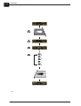
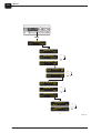
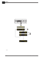
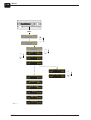
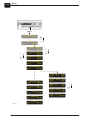
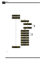
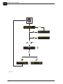
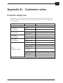
User’s Manual
Control Panel
User's Manual
Control Panel
T2543
Edition AC, February 2006
This manual has part No 51438 (GB)
0-2
Introduction
This manual
Part 0: Introduction
This manual
This manual is published by:
GLUNZ & JENSEN A/S
Haslevvej 13
DK-4100 Ringsted
Denmark
Phone:
+45 57 68 81 81
E-mail:
[email protected]
Internet:
www.glunz-jensen.com
Copyright © 2006 by GLUNZ & JENSEN A/S.
Safety
#
Always read the Safety Instruction Manual part No 21741 before installing or
operating the equipment.
1.00.00.
0605
User's Manual - Control Panel
Introduction
This manual
Reservations
• This manual was written and illustrated using the best possible information
available at the time of publication.
• Any differences between this manual and the equipment reflect improvements
introduced after the publication of the manual.
• Changes, technical inaccuracies and typographic errors will be corrected in
subsequent editions.
• As a part of our policy of continuous improvement, we reserve the right to alter
design and specifications without further notice.
Notes, Cautions, and Warnings !
Throughout the manual notes, cautions, and warnings are written in bold like the
example below:
"
Help text is available for some functions/parameters only.
Explanation
Symbol
"
$
#
Meaning
Note
Caution
Warning
Explanation
The operator should observe and/or act according to the
information in order to obtain the best possible function of
the equipment.
The operator must observe and/or act according to the
information in order to avoid any mechanical or electrical
damage to the equipment.
The operator must observe and/or act according to the
information in order to avoid any personnel injury.
Keep this manual with the machine for reference at all times.
User's Manual - Control Panel
0605
0-3
0-4
Introduction
This manual
0605
User's Manual - Control Panel
0-5
Table of Contents
Part 0: Introduction . . . . . . . . . . . . . . . . . . . . . . . . . . . . . . . . . . . . 0-2
This manual. . . . . . . . . . . . . . . . . . . . . . . . . . . . . . . . . . . . . . . . . . . . . . . . . . . . . 0-2
Safety . . . . . . . . . . . . . . . . . . . . . . . . . . . . . . . . . . . . . . . . . . . . . . . . . . . . . . . 0-2
Reservations . . . . . . . . . . . . . . . . . . . . . . . . . . . . . . . . . . . . . . . . . . . . . . . . . . 0-3
Notes, Cautions, and Warnings ! . . . . . . . . . . . . . . . . . . . . . . . . . . . . . . . . . . . . 0-3
Part 1: General information . . . . . . . . . . . . . . . . . . . . . . . . . . . . . . 1-1
Introduction to this manual . . . . . . . . . . . . . . . . . . . . . . . . . . . . . . . . . . . . . . . . . . 1-1
Symbols used in this manual . . . . . . . . . . . . . . . . . . . . . . . . . . . . . . . . . . . . . . . . . 1-3
Part 2: Functions. . . . . . . . . . . . . . . . . . . . . . . . . . . . . . . . . . . . . . 2-1
Introduction . . . . . . . . . . . . . . . . . . . . . . . . . . . . . . . . . . . . . . . . . . . . . . . . . . . . . 2-1
Keys and indicators . . . . . . . . . . . . . . . . . . . . . . . . . . . . . . . . . . . . . . . . . . . . . . . 2-1
Power on indicator . . . . . . . . . . . . . . . . . . . . . . . . . . . . . . . . . . . . . . . . . . . . . . 2-1
Stand-by key . . . . . . . . . . . . . . . . . . . . . . . . . . . . . . . . . . . . . . . . . . . . . . . . . . 2-1
Up/down keys . . . . . . . . . . . . . . . . . . . . . . . . . . . . . . . . . . . . . . . . . . . . . . . . . 2-1
Display . . . . . . . . . . . . . . . . . . . . . . . . . . . . . . . . . . . . . . . . . . . . . . . . . . . . . . 2-2
Selection keys . . . . . . . . . . . . . . . . . . . . . . . . . . . . . . . . . . . . . . . . . . . . . . . . . 2-2
Quick-set key. . . . . . . . . . . . . . . . . . . . . . . . . . . . . . . . . . . . . . . . . . . . . . . . . . 2-3
Alarm lamp . . . . . . . . . . . . . . . . . . . . . . . . . . . . . . . . . . . . . . . . . . . . . . . . . . . 2-3
Turn roller key . . . . . . . . . . . . . . . . . . . . . . . . . . . . . . . . . . . . . . . . . . . . . . . . . 2-3
Manual replenish key . . . . . . . . . . . . . . . . . . . . . . . . . . . . . . . . . . . . . . . . . . . . 2-3
Help-text key . . . . . . . . . . . . . . . . . . . . . . . . . . . . . . . . . . . . . . . . . . . . . . . . . . 2-4
General control panel functions . . . . . . . . . . . . . . . . . . . . . . . . . . . . . . . . . . . . . . . 2-6
Operating modes . . . . . . . . . . . . . . . . . . . . . . . . . . . . . . . . . . . . . . . . . . . . . . . 2-6
Off mode . . . . . . . . . . . . . . . . . . . . . . . . . . . . . . . . . . . . . . . . . . . . . . . . . . . . . 2-6
Stand-by mode . . . . . . . . . . . . . . . . . . . . . . . . . . . . . . . . . . . . . . . . . . . . . . . . 2-6
Process mode . . . . . . . . . . . . . . . . . . . . . . . . . . . . . . . . . . . . . . . . . . . . . . . . . 2-7
Turning main power on (Turn into OFF mode) . . . . . . . . . . . . . . . . . . . . . . . . . . . 2-9
Turning main power off (From OFF mode). . . . . . . . . . . . . . . . . . . . . . . . . . . . . . 2-9
Start-up (Switching into stand-by mode) . . . . . . . . . . . . . . . . . . . . . . . . . . . . . . 2-11
Switching on using the stand-by key . . . . . . . . . . . . . . . . . . . . . . . . . . . . . . 2-11
Switching on using the timer function. . . . . . . . . . . . . . . . . . . . . . . . . . . . . . 2-11
"READY" Display views . . . . . . . . . . . . . . . . . . . . . . . . . . . . . . . . . . . . . . . . 2-11
Shut-down (turn from stand-by to off mode) . . . . . . . . . . . . . . . . . . . . . . . . . . . 2-13
Switching off without using the manual timer function . . . . . . . . . . . . . . . . . . 2-13
Switching off with manual timer function . . . . . . . . . . . . . . . . . . . . . . . . . . . 2-13
Processing. . . . . . . . . . . . . . . . . . . . . . . . . . . . . . . . . . . . . . . . . . . . . . . . . . . 2-15
User's Manual - Control Panel
0605
0-6
Part 3: Menus . . . . . . . . . . . . . . . . . . . . . . . . . . . . . . . . . . . . . . . . 3-1
Detailed menu descriptions . . . . . . . . . . . . . . . . . . . . . . . . . . . . . . . . . . . . . . . . . . 3-1
Introduction. . . . . . . . . . . . . . . . . . . . . . . . . . . . . . . . . . . . . . . . . . . . . . . . . . . 3-1
Menu structure. . . . . . . . . . . . . . . . . . . . . . . . . . . . . . . . . . . . . . . . . . . . . . . . . . . 3-2
Programs. . . . . . . . . . . . . . . . . . . . . . . . . . . . . . . . . . . . . . . . . . . . . . . . . . . . . . . 3-5
Changing program settings (set) or, selecting a program (select) . . . . . . . . . . . . . . 3-7
Auto program. . . . . . . . . . . . . . . . . . . . . . . . . . . . . . . . . . . . . . . . . . . . . . . . . . 3-9
Statistics . . . . . . . . . . . . . . . . . . . . . . . . . . . . . . . . . . . . . . . . . . . . . . . . . . . . . . 3-11
Functions . . . . . . . . . . . . . . . . . . . . . . . . . . . . . . . . . . . . . . . . . . . . . . . . . . . . . 3-13
Eject plate . . . . . . . . . . . . . . . . . . . . . . . . . . . . . . . . . . . . . . . . . . . . . . . . . . . 3-13
Timer (Manual) . . . . . . . . . . . . . . . . . . . . . . . . . . . . . . . . . . . . . . . . . . . . . . . 3-13
Gum rinse . . . . . . . . . . . . . . . . . . . . . . . . . . . . . . . . . . . . . . . . . . . . . . . . . . . 3-15
Wash flush . . . . . . . . . . . . . . . . . . . . . . . . . . . . . . . . . . . . . . . . . . . . . . . . . . 3-15
Gum flush . . . . . . . . . . . . . . . . . . . . . . . . . . . . . . . . . . . . . . . . . . . . . . . . . . . 3-15
Rdy to clean (Ready to clean) . . . . . . . . . . . . . . . . . . . . . . . . . . . . . . . . . . . . . 3-15
Turn roller . . . . . . . . . . . . . . . . . . . . . . . . . . . . . . . . . . . . . . . . . . . . . . . . . . . 3-17
Alarms . . . . . . . . . . . . . . . . . . . . . . . . . . . . . . . . . . . . . . . . . . . . . . . . . . . . . . . 3-17
Setup . . . . . . . . . . . . . . . . . . . . . . . . . . . . . . . . . . . . . . . . . . . . . . . . . . . . . . . . 3-19
Control panel . . . . . . . . . . . . . . . . . . . . . . . . . . . . . . . . . . . . . . . . . . . . . . . . . 3-19
left key . . . . . . . . . . . . . . . . . . . . . . . . . . . . . . . . . . . . . . . . . . . . . . . . . . . 3-19
Disp (display) . . . . . . . . . . . . . . . . . . . . . . . . . . . . . . . . . . . . . . . . . . . . . . 3-21
Display light / Display contrast . . . . . . . . . . . . . . . . . . . . . . . . . . . . . . . . . . 3-23
Sound. . . . . . . . . . . . . . . . . . . . . . . . . . . . . . . . . . . . . . . . . . . . . . . . . . . . 3-23
Black out . . . . . . . . . . . . . . . . . . . . . . . . . . . . . . . . . . . . . . . . . . . . . . . . . 3-23
Edit lock . . . . . . . . . . . . . . . . . . . . . . . . . . . . . . . . . . . . . . . . . . . . . . . . . . 3-25
Plate sizes . . . . . . . . . . . . . . . . . . . . . . . . . . . . . . . . . . . . . . . . . . . . . . . . . . . 3-26
Replace periods . . . . . . . . . . . . . . . . . . . . . . . . . . . . . . . . . . . . . . . . . . . . . . . 3-27
Replenishment. . . . . . . . . . . . . . . . . . . . . . . . . . . . . . . . . . . . . . . . . . . . . . . . 3-29
Preferences . . . . . . . . . . . . . . . . . . . . . . . . . . . . . . . . . . . . . . . . . . . . . . . . . . 3-31
Information . . . . . . . . . . . . . . . . . . . . . . . . . . . . . . . . . . . . . . . . . . . . . . . . . . 3-33
Absolute values . . . . . . . . . . . . . . . . . . . . . . . . . . . . . . . . . . . . . . . . . . . . . 3-33
Auto timer . . . . . . . . . . . . . . . . . . . . . . . . . . . . . . . . . . . . . . . . . . . . . . . . . . . 3-35
Clock . . . . . . . . . . . . . . . . . . . . . . . . . . . . . . . . . . . . . . . . . . . . . . . . . . . . . . 3-37
Monitor . . . . . . . . . . . . . . . . . . . . . . . . . . . . . . . . . . . . . . . . . . . . . . . . . . . . . 3-37
Service . . . . . . . . . . . . . . . . . . . . . . . . . . . . . . . . . . . . . . . . . . . . . . . . . . . . . . . 3-37
Part 4: Off mode menu. . . . . . . . . . . . . . . . . . . . . . . . . . . . . . . . . . 4-1
Description . . . . . . . . . . . . . . . . . . . . . . . . . . . . . . . . . . . . . . . . . . . . . . . . . . . . . 4-1
How to enter the off mode menu . . . . . . . . . . . . . . . . . . . . . . . . . . . . . . . . . . . . 4-1
Part 5: Alarms and messages . . . . . . . . . . . . . . . . . . . . . . . . . . . . . 5-1
General . . . . . . . . . . . . . . . . . . . . . . . . . . . . . . . . . . . . . . . . . . . . . . . . . . . . . . . . 5-1
Wait, busy, alarm etc. . . . . . . . . . . . . . . . . . . . . . . . . . . . . . . . . . . . . . . . . . . . 5-1
Status messages . . . . . . . . . . . . . . . . . . . . . . . . . . . . . . . . . . . . . . . . . . . . . . . 5-2
0605
User's Manual - Control Panel
0-7
Alarms/messages list. . . . . . . . . . . . . . . . . . . . . . . . . . . . . . . . . . . . . . . . . . . . . . . 5-3
How to read the alarms/messages list . . . . . . . . . . . . . . . . . . . . . . . . . . . . . . . . . 5-3
Abbreviations used in the alarms/messages list . . . . . . . . . . . . . . . . . . . . . . . . . . 5-3
Explanation of the alarm display. . . . . . . . . . . . . . . . . . . . . . . . . . . . . . . . . . . . . . 5-10
Displaying alarms. . . . . . . . . . . . . . . . . . . . . . . . . . . . . . . . . . . . . . . . . . . . . . 5-10
User action . . . . . . . . . . . . . . . . . . . . . . . . . . . . . . . . . . . . . . . . . . . . . . . . . . 5-11
Exit . . . . . . . . . . . . . . . . . . . . . . . . . . . . . . . . . . . . . . . . . . . . . . . . . . . . . 5-11
OK . . . . . . . . . . . . . . . . . . . . . . . . . . . . . . . . . . . . . . . . . . . . . . . . . . . . . . 5-11
Initialization fail . . . . . . . . . . . . . . . . . . . . . . . . . . . . . . . . . . . . . . . . . . . . . . . 5-13
"Fail not found" . . . . . . . . . . . . . . . . . . . . . . . . . . . . . . . . . . . . . . . . . . . . . 5-13
Appendix A: Customers notes . . . . . . . . . . . . . . . . . . . . . . . . . . . . . A-1
Parameter settings lists . . . . . . . . . . . . . . . . . . . . . . . . . . . . . . . . . . . . . . . . . . . . . A-1
User's Manual - Control Panel
0605
0-8
0605
User's Manual - Control Panel
General information
Introduction to this manual
Part 1: General information
Introduction to this manual
The control panel described in this manual is for Rinse-Gum Units, as specified on
page 0-2, offline as well as online.
On the next pages are general description of the control panel keys and indicators
followed by descriptions of operation and programming procedures and menu
structure with detailed functional descriptions.
$
Always read the Safety Instruction Manual part no 21741 before starting up
the equipment.
T2543
User's Manual - Control Panel
0605
1-1
1-2
General information
Introduction to this manual
Action by operator
Switch processor’s main
switch to "I"
(= on) or "0" (= off).
Press quick-set key
Press stand-by key
Replenish key not in use for this
processor.
Use up/down keys to
scroll between menu
items.
Press turn roller key
Use up/down keys to
adjust a value on the
display.
Press help-text key
Action by Control panel
The display
continuously changes
between two different
messages.
MAN.REPL.
EXIT
100ml
START
MAN.REPL.
EXIT
90ml
/
1) The arrow shows
display changes and/or
function starts/stops
when related soft key is
pressed, or
2) The arrow shows
display changes and/or
automatic function
starts/-stops at time-out
etc.
Countdown
(Sometimes visual
on the display)
0605
Indicators on control
panel :
Power on
Main power supply has
been off !
(lamp flashing)
Status signal
(lamp lit)
Alarm signal
(lamp flashing)
Bib-sound (not visual)
User's Manual - Control Panel
General information
Symbols used in this manual
Symbols used in this manual
Opposite are shown the various symbols used in illustrations throughout this manual.
The symbols are used for explanation of the various control panel functions and
display messages.
The symbols shown in the upper part of the table are meant as a help to inform
the operator which button to press in the situations described later in this manual.
The symbols shown in the lower part of the table inform the operator of various
control panel changes and functions.
User's Manual - Control Panel
0605
1-3
1-4
General information
Symbols used in this manual
0605
User's Manual - Control Panel
Functions
Introduction
Part 2: Functions
Introduction
In this chapter is described the function of the keys and indicators on the control panel
as well as general control panel functions which are not directly related to the menu
functions.
4
1
3
8
ready
timer
2
p1
1220pl
menu
9
10
T2544
6
5
7
Keys and indicators
Power on indicator (1)
Indicates that power is on (main switch is set to "I"). When flashing it indicates that
main power supply has been off for a while. When starting up the processor - pressing
the stand-by key (2) - the indicator stops flashing.
Stand-by key (2)
Switches the processor from off mode into stand-by mode and opposite.
See description of "Off mode" and "Stand-by mode" on page 2-6.
Up/down keys (3)
Use the up/down keys to
• Scroll between display settings in the upper right corner. See "DISP (display)" on
page 3-23.
• Scroll between menu items.
• Adjust settings of various programs/parameters.
User's Manual - Control Panel
0605
2-1
2-2
Functions
Keys and indicators
4
1
3
8
ready
timer
2
p1
1220pl
menu
9
10
T2544
6
5
7
Display (4)
The display holds 2 lines of 16 characters each:
The top line displays:
Left:
- Processor status: Wait, ready, alarm etc. See detailed description in
the table with status messages in Part 5.
- Alarms, messages, and help text.
- Input/output device name* (for service technicians).
Right:
- Values.
- Program parameters/settings*.
- Status of input/output device* (for service technicians).
The bottom line displays:
Left/right:
- Functions of left and right selection keys.
Middle:
- Selected program or active processor tank.
Selection keys (5)
Key functions are displayed in the bottom line of the display (4).
Use keys ex. to :
• Enter the left-key function. See "Left key" on page 3-21.
• Enter menus/parameters.
• Confirm changed values/parameters.
• Cancel adjustments/exit functions.
• Start/stop various functions.
*) Units can be set in Metric or US values. To be set by a service technician.
0605
User's Manual - Control Panel
Functions
Keys and indicators
Quick-set key (6)
Activating the quick-set key enables you to view and change settings for the active
function.
The function of the key depends on the processor mode or which parameter is active.
The quick-set key can be activated in the following functions:
• READY (stand-by mode):
Change of settings or resetting of the active display selection (DISP). See description
of "DISP (display)" on page 3-23.
• FUNCTIONS:
Manual TIMER - change of start-up day and time. See description on page 3-15.
Alarm lamp (7)
The alarm lamp will indicate occurrence of abnormal conditions/alarms. At the same
time the top line of the display shows "ALARM".
Some alarms will be combined with a sound signal.
The different behaviors of the alarm lamp combined with sound are described in detail
in Part 5 "Alarms and messages".
Turn roller key (8)
Key for positioning of rollers for easy service:
• Press the turn roller key. The display shows "ADJUST ROLLER".
• Press the up-key or down-key to turn rollers slightly forward or backwards for
positioning for easy removal/mounting.
• Press "EXIT" to return to the stand-by display.
The turn roller function is also available from the FUNCTIONS menu as described on
page 3-19.
Manual replenish key (9)
Not in use for this processor.
User's Manual - Control Panel
0605
2-3
2-4
Functions
Keys and indicators
Help-text key (10)
"
Help text is available for some functions/parameters only.
The help-text key gives short explanations:
• For menus and parameters with abbreviations.
• To all alarms and messages.
Pressing the help-text key while processing, programming, or scrolling through alarms
or functions/parameters will display the help-text.
ready
timer
p1
1220pl
menu
10
No alarms, StandBy and Ready
EXIT
T2572-1
For more detailed information of the control panel menus, the parameters and alarm
messages please refer to descriptions in this manual.
Help-text key functions
... when scrolling through menus and parameters:
Press once and the help-text function will shortly explain the displayed menu/function
or parameter.
0605
User's Manual - Control Panel
Functions
Keys and indicators
Help-text key functions
...when alarms and messages are displayed:
a) - Single alarm/message:
When "ALARM" (or "WAIT") is displayed press the help-text key once. The help-text
function will display :
– The actual alarm in an abbreviated version, and
– The number of the alarm messages (e.g. "1/1" = number/count), and
– For some alarm types the current value deviation.
Press the help-text key once more and a full text version of the actual alarm will scroll
through the display. The full text version starts with a unique alarm identification
number. Use this number to find the alarm in the list of alarms and messages in Part 5.
Press "EXIT" to exit alarm messages.
a
ALARM
TIMER
P1
b
1220pl
MENU
TEMP LO DRY -1C
EXIT
1/1
ALARM
TIMER
P1
1220pl
MENU
TEMP LO DRY -1C
EXIT
1/2
TOPUP WASH?
EXIT
2/2
23: Not level in wash. Top up?
EXIT
T2572-2
b) - Multiple alarms/messages:
When "ALARM" (or "WAIT") is displayed press the help-text key once. The help-text
function will display the actual alarm in an abbreviated version. If two or more alarms
occur the help-text function will display e.g. "1/2" informing the operator that this
alarm is one of two present. Press down key to see next alarm ("2/2") and press the
help-text key once more to see the full text version of the actual alarm.
A complete list with alarm messages is also included in Part 5.
User's Manual - Control Panel
0605
2-5
2-6
Functions
General control panel functions
General control panel functions
Operating modes
The processor can be in one of 3 different modes when main power is turned on:
Off mode
Power is on (main switch is set to "I").
The display is black, and the power on indicator is lit (or flashing)
Functions in OFF mode:
• All processing functions are off.
• Timer function may be active (optional) *.
If active the display shows the day and time for next automatic start-up. See page
3-15 and 3-37 for decriptions of timer function.
• Possibility of entering the processors functions and preferences menus in order to
reset counters or make changes to fill/replenishment strategy.
See Part 4 for detailed description of the functions available in off mode.
Stand-by mode
When the processor is in stand-by mode (and display shows "READY") it is ready to
receive a plate from the feed table or imagesetter.
The display shows:
• "READY", "WAIT" or "ALARM". See table with status signals in Part 5.
• E.g. number of plates processed. See "DISP (display)" on page 3-23
• Functions of left and right selection keys. See "Left key" on page 3-21
• Selected program. See "Programs" on page 3-5.
Functions in STAND-BY mode:
• Temperature controls are on.
• Level controls are on.
• Time replenishment function is active.
• Jog function is active. The jog function makes the transport rollers turn for a short
while at intervals to prevent crystallization of chemicals on the rollers.
• Keyboard functions can be activated.
*) The function can be set by the user. The function is described later in this manual.
0605
User's Manual - Control Panel
Functions
General control panel functions
Process mode
Process mode means that the processor is processing a plate, either from the feed table,
or imagesetter (display shows "BUSY" or "READY").
Functions in PROCESS mode:
• Transport system runs with the set speed.
• Level controls are on.
• Dryer and blowers are on. Dryer temperature control is on for models with
temperature sensor.
• Replenishment systems add replenishment to the various tanks as set in the specific
parameters.
• The rollers and various wash and gum spray pumps runs at relevant times before
the plate enters the respective tanks.
• The processor automatically returns to stand-by mode shortly after the last plate
exits.
User's Manual - Control Panel
0605
2-7
2-8
Functions
General control panel functions
Initializing,
Please wait...
(OFF)
(OFF)
T2563
0605
User's Manual - Control Panel
Functions
General control panel functions
Turning main power on (Turn into OFF mode)
See upper diagram.
• Turn main switch to "I" (= on). The system will initialize.
• The power on indicator will start flashing and the processor will wait in off mode
(display is black).
"Off mode" functions is described on page 2-6.
"Start-up" of the processor is described on page 2-11.
Turning main power off (From OFF mode)
See lower diagram.
• Please make sure that the processor is in off mode (display is black). If not, use the
stand-by key to switch the processor from stand-by mode into off mode. Display
will turn black.
• When the processor is in off mode turn main switch to "0" (= off).
"
Power supply should only be turned off for holidays or for maintenance and
servicing purposes. Normally the processor should be switched into off mode
only.
"Off mode" functions is described on page 2-6.
User's Manual - Control Panel
0605
2-9
2-10
Functions
General control panel functions
(OFF)
[B]
READY
STAT
P1
1034pl
MENU
READY
XXXXX
P1
XXXXxx
MENU
[D]
OFF
Start: TUE 07:30
AUTO-START 10
OFF
Start: TUE 07:30
READY
STAT
P1
[C]
1034pl
MENU
T2566
0605
User's Manual - Control Panel
Functions
General control panel functions
Start-up (Switching into stand-by mode)
There are 2 ways of switching the processor into stand-by mode:
– using the STAND-BY key, or
– using the TIMER function.
[B] Switching on using the stand-by key
See diagram opposite.
• Main power must be on and the processor in off mode (display is black). See
"Turning main power on" on page 2-9.
• Press the stand-by key.
[C] Switching on using the timer function
See diagram opposite.
The processor’s timer function enables automatic start-up.
• If timer function is activated and main power is turned on, the next start-up time
will be shown in the bottom line of the display.
• The display will show "AUTO-START X" 10 seconds before start-up and a beeper
will beep for a few seconds to advise the operator.
• The processor will automatically switch into stand-by mode.
"
It is possible to start-up the processor manually any time by pressing the
stand-by key even though the timer function is active.
Starting the processor manually will override the settings in the timer
function.
See description of "Switching off with manual timer function" on page 2-13
and "Auto timer" on page 3-37.
[D] "READY" Display views
The ready display view may vary depending on settings made in "LEFT KEY" and
"DISP" as described on page 3-21 and 3-23.
User's Manual - Control Panel
0605
2-11
2-12
Functions
General control panel functions
READY
STAT
P1
1034pl
MENU
CLEANING GUM
STOP
5 min.
[E]
STOPPING CLEAN
(OFF)
READY
STAT
P1
1034pl
MENU
EXIT
PROGRAMS
ENTER
FUNCTIONS
EXIT
ENTER
EJECT PLATE
EXIT
START
TIMER
EXIT
[F]
ENTER
TUESDAY
CANCEL
07:30
OK
TURN OFF NOW?
NO
YES
CLEANING GUM
STOP
5 min.
OFF
Start: TUE 07:30
T2567
0605
User's Manual - Control Panel
Functions
General control panel functions
Shut-down (turn from stand-by to off mode)
There are 2 ways of switching the processor off:
– Switch off without using the manual timer function, or
– Switch off with manual timer function.
[E] Switching off without using the manual timer function
• From stand-by mode press the stand-by key.
• If configured for gum cleaning the display will show "CLEANING GUM". The
processor will run the gum-rinse cycle and subsequently switch to off mode.
The "CLEANING GUM" message is explained in "Alarms and messages" in Part 5.
• All processing functions are now off, but timer function is active (if set).
[F] Switching off with manual timer function
Using the manual timer function enables you to turn the processor off and at the same
time select day and time for next automatic start-up.
• Enter the timer function using the left-key function (if set to TIMER), or
• From stand-by mode press the "MENU" selection key.
• Press down key to select FUNCTIONS.
• Press the "ENTER" selection key to enter FUNCTIONS.
• Press down key to select the TIMER function.
• Press "ENTER" to enter TIMER function.
• The display will show the proposed start-up day and time. Press "OK" to activate the
manual timer function and turn off the processor with the set day and time for next
start-up, or change settings:
– Press the quick-set key to make new start-up settings. A cursor will appear in the
top line in the display:
– Press up/down keys to select the week day on which the processor should
automatically start up again and press OK.
– Press up/down keys to select the hour on which the processor should
automatically start up and press OK.
– Press up/down keys to select the minute on which the processor should
automatically start up and press OK.
– Press OK to activate the timer function.
• The message "TURN OFF NOW?" will be prompted. Press "YES" to accept.
The processor will switch into off mode and show day and time for next start-up in
the display, e.g. "Start TUE 07:30".
All processing functions are now off, but time replenish and timer functions are
active (if set to ON).
• The manual timer function is also briefly described on page 3-15.
• The processor will automatically start-up on the day and time shown in the display.
• To overrule the timer function simply press the stand-by key and the processor will
start-up as shown in example [B].
See also the description of "Auto timer" function on page 3-37.
User's Manual - Control Panel
0605
2-13
2-14
Functions
General control panel functions
READY
STAT
BUSY
STAT
P1
1034pl
MENU
P1\
1034pl
MENU
READY
1034pl
STAT P1\
MENU
P1\
P1|
P1/
P1P1\
READY
STAT
P1
1035pl
MENU
T2568
0605
User's Manual - Control Panel
Functions
General control panel functions
Processing
• The processor must be in stand-by mode (display shows "READY").
• When a plate is entered, either manually (offline) or automatically (online) the
processor switches into process mode:
– The display will change to show "BUSY".
(If the processors is configured to READY DELAY. To be done by a service
technician).
– The alarm lamp will lit. (If the processor is configured to "ready delay". To be
done by a service technician).
– A continuously changing processing symbol behind the selected program
number will appear e.g. "P1/".
• A few seconds after the input sensors are released (to be configured by a service
technician) the display will change to "READY".
• The processor automatically returns to stand-by mode shortly after the last plate
exits.
User's Manual - Control Panel
0605
2-15
2-16
Functions
General control panel functions
0605
User's Manual - Control Panel
Menus
Detailed menu descriptions
Part 3: Menus
Detailed menu descriptions
Introduction
In this chapter is described in detail the subjects of the menus available on the control
panel when switched on.
The descriptions of the control panel menus are made in the same order as the
building up of the menu structure itself.
User's Manual - Control Panel
0605
3-1
3-2
Menus
Menu structure
Menu structure
The diagram below and opposite illustrates the control panel menus available for the
daily operator of the plate processor.
ready
timer
p1
= Edit lock
1220pl
menu
= Service lock
( ) = Parameters available
depending on setup
and/or configuration
(MENU)
PROGRAMS
PROGRAM Px (SET)
PROGRAM Px (SELECT)
AUTO PROGRAM
STATISTICS
PLATES
AREA
(WASH SECTION)
(GUM SECTION)
BRUSH
HISTORY
FUNCTIONS
EJECT PLATE
TIMER
(GUM RINSE)
WASH FLUSH
GUM FLUSH
RDY TO CLEAN
TURN ROLLER
SPEED
PAR. PLATES
WASH STATUS
(W WATER)
(W CHNG)
GUM STATUS
(G GUM)
(G CHNG)
BRUSH
ADJUST ROLLERS
ALARMS
SETUP
0605
CONTROL PANEL
LEFT KEY *
DISP **
DISPLAY LIGHT
DISPLAY CONTRAST
SOUND
BLACK OUT
EDIT LOCK
T2541_Q3-RGU, 1/2
User's Manual - Control Panel
Menus
Menu structure
ready
timer
p1
1220pl
menu
**) DISPLAY:
xxxxxx pl
xxxxxx m2
xxx cm/min
(W xxx ml/m2
PLATE SIZES
S1 650x550mm
..
..
12 650x550mm
REPLACE PERIODS
(W WATER)
(W LIFE DAYS)
(G GUM)
(G LIFE DAYS)
REPLENISHMENT
(W RPL)
(W PUMP MIN)
PREFERENCES
OFFRPL WARN
(AUTO G RINSE)
LEVEL SETUP
INFORMATION
"processor type"
Q-3 xx.xx.xx X
ABSOLUTE VALUES
AUTO TIMER
START MON
STOP MON
..
..
START SUN
STOP SUN
CLOCK
XX-XX-XXXX XX:XX
MONITOR
Section WASH
Section GUM
Section DRY
Section TRANS
Section PROC
Section MMI
(Section SETTER)
= PLATES
= AREA
= SPEED
= WASH REPL)
*) LEFT KEY:
NONE
STATISTICS
TIMER
PROGRAM
EJECT
(W FILL)
(W RESET)
(W TOP UP)
(G RESET)
PLATES
AREA
HOURS
SERVICE
T2541_Q3-RGU, 2/2
User's Manual - Control Panel
0605
3-3
3-4
Menus
Menu structure
READY
PROG
P1
EXIT
1200pl
MENU
PROGRAMS
ENTER
PROGRAM P1
EXIT
SET
PROGRAM P1
EXIT
SELECT
PROGRAM P1
CANCEL
OK
PROGRAM P4
CANCEL
OK
PROGRAM P4
EXIT
SET
PROGRAM P4
EXIT
SELECT
AUTO PROGRAM OFF
EXIT
SET
T2608
0605
User's Manual - Control Panel
Menus
Programs
Programs
It is possible to choose between 4 processing programs, each programmable with
different transport times for various processing jobs.
The table below shows the various program parameters.
Parameter
SPEED
Setting
XX cm/min. (in/min.) Transport time.
PAR. PLATES
"
Description
ON/OFF Select if the processor must be able to process
parallel plates.
Make notes of the settings for these parameters in the table in the appendix.
User's Manual - Control Panel
0605
3-5
3-6
Menus
Programs
READY
PROG
P1
c
1200pl
MENU
b
a
EXIT
READY
PROG
90cm/min
P1
MENU
PROGRAMS
ENTER
PROGRAM P1
EXIT
SET
PROGRAM P1
EXIT
SELECT
PROGRAM P1
CANCEL
OK
PROGRAM P4
CANCEL
OK
PROGRAM P4
EXIT
SELECT
SPEED
EXIT
90cm/min
SET
PROGRAM P4
EXIT
SET
SPEED
CANCEL
90cm/min
OK
SPEED 110cm/min
CANCEL
OK
PAR PLATES
EXIT
OFF
SET
SPEED
EXIT
110cm/min
SET
T2578
0605
User's Manual - Control Panel
Menus
Programs
Changing program settings (set) or, selecting a program (select)
a) • The stand-by display bottom line shows the currently selected program e.g. "P1".
• Enter the PROGRAMS menu and press "ENTER".
• The display now shows the currently selected program with the possibility to
enter program settings by pressing "SET".
• To choose another program use the up/down keys to go to the SELECT
opportunity.
Press "SELECT" and use the up/down keys to select another program number.
Press "OK" to confirm.
• Press "EXIT" to exit the programs menu or press the up/down keys to go to
"SET" opportunity for changing the program settings.
• Press "EXIT" until the display shows the stand-by display. Note that the selected
program number appears in the bottom line.
b) • If the left selection key is set to "PROGRAM" (display shows "PROG") the
program settings can be activated directly by pressing the left selection key
when the processor is in stand-by mode.
c)
• Quick-set
Some of the program parameters listed on page 3-5 can also be selected as a
default display setting. See description of "DISP (display)" on page 3-23.
The values of the parameters can then easily be changed by scrolling through the
parameter list directly from stand-by mode and pressing the quick-set key.
The display view will automatically return to the parameter selected in "DISP
(display)".
User's Manual - Control Panel
0605
3-7
3-8
Menus
Programs
ready
timer
p1
1220pl
menu
(MENU)
EXIT
PROGRAMS
ENTER
PROGRAM P1
EXIT
SET
PROGRAM P1
EXIT
SELECT
AUTO PROGRAM ON
EXIT
SET
AUTO PROGRAM
EXIT
ON
OK
AUTO PROGRAM OFF
EXIT
OK
AUTO PROGRAM OFF
EXIT
SET
PROGRAM P1
EXIT
SET
PROGRAM P1
EXIT
SELECT
PROGRAM P1
CANCEL
OK
PROGRAM P2
CANCEL
OK
T2619_Q3
0605
User's Manual - Control Panel
Menus
Programs
Auto program
Some online processors are configured for program selection from the setter.
The auto program function allows the operator temporarily to override the program
selected through the setter interface by setting auto program to OFF.
Follow the procedure below to switch auto program function off:
• Enter the PROGRAMS menu and press "ENTER".
• The display now shows the currently selected program.
• Use the up or down key to scroll to the AUTO PROGRAM function. Press "SET" to
change setting.
• Use the down key to select "OFF" and press "OK".
• Press the up or down key to scroll to the selected program. Display must show
program no and "SELECT".
• Press "SELECT" and use the up/down keys to select another program number. Press
"OK" to confirm.
• Press "EXIT" twice to return to stand-by mode.
To switch auto program on manually follow the same procedure and set auto program
to ON. When set to ON program selection can no longer be made from the control
panel but is done from the setter.
The auto program will automatically return to ON if power has been switched off.
User's Manual - Control Panel
0605
3-9
3-10
Menus
Programs
ready
timer
p1
1220pl
menu
(MENU)
EXIT
PROGRAMS
ENTER
STATISTICS
EXIT
ENTER
PLATES
EXIT
1220
RESET
AREA
EXIT
147
RESET
EXIT
HISTORY
ENTER
T2580
0605
User's Manual - Control Panel
Menus
Statistics
Statistics
The statistics function can be used for viewing and for some resetting the values for the
parameters listed below.
This function is useful if information of the total values is needed for specific periods
e.g. each week or month.
Sub-menu
Parameter
Description
Parameters in bold-italic are available for some configurations only.
Total number of plates processed since counter reset.
PLATES
Total area processed since counter reset.
AREA
WASH STATUS
W WATER
WASH tank
W CHNG
GUM STATUS
G GUM
GUM tank
G CHNG
BRUSH
HISTORY
Displays status in % based on W WATER and
W CHNG.
Area of plate (in m2) left to be processed until wash water
change is recommended.
If displayed value is negative (-) the processed plate area
has exceeded the max. setting.
Days left to be processed until change of wash water is
recommended.
If displayed value is negative (-) the processed plate area
has exceeded the max. setting.
Displays status in % based on G GUM and
G CHNG.
Area of plate (in m2) left to be processed until gum
change is recommended.
If displayed value is negative (-) the processed plate area
has exceeded the max. setting.
Days left to be processed until change of gum is
recommended.
If displayed value is negative (-) the processed plate area
has exceeded the max. setting.
Area of plate (in m2) left to be processed until change of
brushes is recommended.
If displayed value is negative (-) the processed plate area
has exceeded the max. setting.
"
For service purposes.
This parameter displays a list with the last 10 changes in
software configuration, unexpected system behaviors, etc.
See also "DISP" (display) on page 3-23.
User's Manual - Control Panel
0605
3-11
3-12
Menus
Statistics
ready
timer
p1
1220pl
menu
(MENU)
EXIT
PROGRAMS
ENTER
FUNCTIONS
EXIT
ENTER
EJECT PLATE
EXIT
START
[G]
TIMER
[H]
EXIT
EXIT
ALARMS
ENTER
ENTER
GUM RINSE
EXIT
ENTER
[J]
WASH FLUSH
EXIT
START
[K]
GUM FLUSH
EXIT
[L]
START
RDY TO CLEAN OFF
EXIT
SET
[M]
TURN ROLLER
EXIT
[N]
SET
[O]
T2573
0605
User's Manual - Control Panel
Menus
Functions
Functions
The functions settings are actions which are not directly related to the processing
programs.
[G] Eject plate
Use the eject plate function to remove a plate left in the processor due to e.g. power
failure.
The eject plate function has both forward and reverse motion.
$
Plates jammed in the processor must be removed manually.
• Enter the "EJECT PLATE" function.
• Press "EJECT" to activate the forward motion function.
If reverse transport is needed press the quick-set key to switch from "EJECT" to
"REVERSE". Press "REVERSE" to active the function.
• The plate will be transported out of the processor.
• When the plate has left the processor press "STOP".
• Press "EXIT" to return to stand-by mode.
If the eject plate function has been set to "REVERSE" with the quick-set key the
function will not reset to "EJECT" unless the control panel is switched off. The
quick-set key works as an on/off function.
[H] Timer (Manual)
(See diagram opposite)
The manual timer function enables you to turn the processor off and at the same time
select a day and time for automatic start-up.
The manual timer key is only used in shut-down situations. Using the manual timer
key overrules the settings made in the AUTO TIMER function.
Detailed description of using the manual timer key is made in "Switching off with
manual timer function" on page 2-13.
"
It is possible to start-up the processor manually any time even though the
timer function is switched on.
Starting the processor manually will override the settings in the timer
function.
See also description of the "Auto timer" function on page 3-37.
User's Manual - Control Panel
0605
3-13
3-14
Menus
Functions
ready
timer
p1
1220pl
menu
(MENU)
EXIT
PROGRAMS
ENTER
FUNCTIONS
EXIT
ENTER
EJECT PLATE
EXIT
START
[G]
TIMER
[H]
EXIT
EXIT
ALARMS
ENTER
ENTER
GUM RINSE
EXIT
ENTER
[J]
WASH FLUSH
EXIT
START
[K]
GUM FLUSH
EXIT
[L]
START
RDY TO CLEAN OFF
EXIT
SET
[M]
TURN ROLLER
EXIT
[N]
SET
[O]
T2573
0605
User's Manual - Control Panel
Menus
Functions
[J] Gum rinse
(Not available if configured to GUM CLOSED)
When activated the processor automatically rinses the gum tank rollers.
• Press “ENTER” and :
– For 1 min. the processor pauses and at the same time, if the processor runs with a
filled gum tank, the gum is emptied into the gum container automatically.
– The processor then starts to let in water to the gum tank from a spray tube down
onto the gum tank rollers to clean them.
– The rollers will turn slowly while the gum rinse function runs. Duration 3 min.
– For another 1 min. the gum tank is emptied automatically.
• When finished the processor automatically switches to “OFF” mode.
[K] Wash flush
See "RDY TO CLEAN" below.
Use this function to activate the wash circulation pump when performing a cleaning
procedure.
[L] Gum flush
See "RDY TO CLEAN" below.
Use this function to activate the gum circulation pump when performing a cleaning
procedure.
[M] Rdy to clean (Ready to clean)
Use this function when performing a cleaning procedure. Set to "YES" and manually
fill up the tanks with water.
When set to "YES":
• All level sensor read-outs will be set to water measurement mode.
• Circulation pumps can still be activated.
• Plates can be fed into the processor.
• The READY message on the display is replaced by a CLEAN message to inform the
operator that setting has been changed.
"
The ready to clean function should be set back to "NO" prior to chemistry fill.
"
The setting will automatically reset to "NO" during processor start-up.
User's Manual - Control Panel
0605
3-15
3-16
Menus
Functions
ready
timer
p1
1220pl
menu
(MENU)
EXIT
PROGRAMS
ENTER
FUNCTIONS
EXIT
ENTER
EJECT PLATE
EXIT
START
[G]
TIMER
[H]
EXIT
EXIT
ALARMS
ENTER
ENTER
GUM RINSE
EXIT
ENTER
[J]
WASH FLUSH
EXIT
START
[K]
GUM FLUSH
EXIT
[L]
START
RDY TO CLEAN OFF
EXIT
SET
[M]
TURN ROLLER
EXIT
[N]
SET
[O]
T2573
0605
User's Manual - Control Panel
Menus
[O] Alarms
[N] Turn roller
This function is useful when removing or mounting rollers for cleaning etc:
• Enter the turn roller function. The display shows ADJUST ROLLER.
• Press the up-key or down-key to turn rollers slightly forward or backwards for
positioning for easy removal/mounting.
The turn roller function is also available by using the turn roller key as described on
page 2-3.
[O] Alarms
When the processor is in stand-by mode or is processing, a number of alarms and
messages can occur.
When one or more alarms occur you can enter this function to see the description of
the different alarms or use the help-text key as described on page 2-4.
A complete list of alarms is included in Part 5 in this manual. The list includes
detailed description of the various alarms and how to act in case an alarm occurs.
See Part 5 for more information about "Alarms and messages".
User's Manual - Control Panel
0605
3-17
3-18
Menus
[O] Alarms
ready
timer
p1
1220pl
menu
(MENU)
EXIT
PROGRAMS
ENTER
SETUP
EXIT
ENTER
CONTROL PANEL
EXIT
ENTER
LEFT KEY
EXIT
NONE
SET
LEFT KEY
CANCEL
NONE
OK
LEFT KEY PROGRAM
CANCEL
OK
LEFT KEY PROGRAM
EXIT
SET
DISP
EXIT
DISP
EXIT
NONE
SET
DISP
CANCEL
NONE
OK
DISP
CANCEL
PLATES
OK
PLATES
SET
T2571
0605
User's Manual - Control Panel
Menus
Setup
Setup
Control panel
The control panel functions and parameters are settings in general and thus not
directly related to processing.
Make a note of the parameter settings made in the control panel menus in the table
in the appendix.
left key
See diagram opposite.
The function assigns a manual function to the left selection key on the stand-by
display.
The assigned function can be executed by pressing the left selection key when the
processor is in stand-by mode.
Below is described the available settings:
Setting
Function
EJECT
(Eject Plate)
When assigned to eject the left key will activate the eject plate function.
See description of "Eject plate" on page 3-15.
PROG
(Program settings)
When assigned to program the left key will give direct access to settings for the
active program. Use the up/down arrow keys to scroll through the different
settings. See "Programs" on page 3-5 for detailed description of program settings.
TIMER
When assigned to the manual timer function pressing the left key will jump
directly to the timer menu. See "Manual timer" on page 3-15 for detailed
instructions.
STAT
(Statistics)
When assigned to statistics function the left key will display the STATISTICS
menu. Use the up/down arrow keys to scroll.
User's Manual - Control Panel
0605
3-19
3-20
Menus
Setup
ready
timer
p1
1220pl
menu
(MENU)
EXIT
PROGRAMS
ENTER
SETUP
EXIT
ENTER
CONTROL PANEL
EXIT
ENTER
LEFT KEY
EXIT
NONE
SET
LEFT KEY
CANCEL
NONE
OK
LEFT KEY PROGRAM
CANCEL
OK
LEFT KEY PROGRAM
EXIT
SET
DISP
EXIT
DISP
EXIT
NONE
SET
DISP
CANCEL
NONE
OK
DISP
CANCEL
PLATES
OK
PLATES
SET
T2571
0605
User's Manual - Control Panel
Menus
Setup
Disp (display)
The upper right corner of the stand-by display shows one of the below listed settings.
In DISP you can make you own choice of which one to display as default. All settings
can be viewed in the stand-by display by pressing the up/down keys. The display will
automatically return to the default setting, e.g. PLATES. Some values can also be
changed or reset using the quick-set key.
Setting
Display will show
Parameters in bold-italic are available for some configurations only.
PLATES
Total number of plates processed (xxxxxxpl).
AREA
Total amount of m2 processed (xxxxxxm2).
SPEED
Actual speed (xxx cm/min) as set in the program settings.
WASH REPL Wash replenish in ml/m2 (Wxxxml/m2) as set in the program settings.
User's Manual - Control Panel
0605
3-21
3-22
Menus
Setup
DISPLAY LIGHT
EXIT
SET
DISPLAY CONTRAST
EXIT
SET
SOUND
EXIT
ON
SET
BLACK OUT
EXIT
OFF
SET
BLACK OUT
CANCEL
OFF
OK
BLACK OUT
CANCEL
ON
OK
BLACK OUT
EXIT
ON
SET
EDIT LOCK
EXIT
OFF
SET
ready
timer
READY
TIMER
p1
1220pl
menu
1220pl
P1
MENU
20 sec.
T2579
0605
User's Manual - Control Panel
Menus
Setup
Display light / Display contrast
See upper diagram.
Use these functions to adjust the display light intensity and contrast:
• Press “SET” to enter the function.
• Use the up/down keys to make the adjustment and when finished press “OK”.
For totally black out of the display see description of the black out function opposite.
Sound
See upper diagram.
Use this function to select whether the beeper should sound or not.
When set to ON the beeper will sound:
• If an important alarm (ex. waste full) occurs.
• When the input sensor(s) is deactivated and the processor is ready to process the
next plate. (Offline installations only).
Exceptions:
The sound functions described below will be active no matter which setting is made in
SOUND:
• When display black out function is active the beeper will sound for all types of
alarms. See "Black out" below.
• When the processor is in off mode:
– The beeper will sound when the top cover has been opened and closed.
Black out
When set to "ON" the black out function will turn off all display lights automatically
after a period of 20 sec. stand-by time provided that the key pad had not been touched
in those 20 sec.
This function is useful when working with light sensitive materials in a darkroom.
To turn on the light again simply press any key.
User's Manual - Control Panel
0605
3-23
3-24
Menus
Setup
DISPLAY LIGHT
EXIT
SET
DISPLAY CONTRAST
EXIT
SET
SOUND
EXIT
ON
SET
BLACK OUT
EXIT
OFF
SET
BLACK OUT
CANCEL
OFF
OK
BLACK OUT
CANCEL
ON
OK
BLACK OUT
EXIT
ON
SET
EDIT LOCK
EXIT
OFF
SET
ready
timer
READY
TIMER
p1
1220pl
menu
1220pl
P1
MENU
20 sec.
T2579
0605
User's Manual - Control Panel
Menus
Setup
Edit lock
See upper diagram.
When edit lock is set to "ON" it is not possible to enter the PROGRAM and SETUP
menus, nor is it possible to change program settings using the quick set key.
Only authorized personnel should be familiar with the code to break the edit lock.
+
User's Manual - Control Panel
+ YES
T31520
The code for opening the program and the setup menus is: up key, down key, "YES":
0605
3-25
3-26
Menus
Setup
Plate sizes
It is possible to enter 12 different sizes for plates.
Length (LEN) and width (WID) and parallel plate selection are entered separately. See
illustration below for setting of plate sizes.
ready
timer
p1
1220pl
menu
(MENU)
EXIT
PROGRAMS
ENTER
SETUP
EXIT
ENTER
CONTROL PANEL
EXIT
ENTER
PLATE SIZES
EXIT
ENTER
S1 60.0* 55.0cm
EXIT
ENTER
REPLACE PERIODS
EXIT
ENTER
REPLENISHMENT
EXIT
ENTER
S1 LEN
EXIT
60.0cm
SET
S1 WID
EXIT
55.0cm
SET
PREFERENCES
EXIT
ENTER
S1 WID
CANCEL
55.0cm
OK
INFORMATION
EXIT
ENTER
S1 WID
CANCEL
80.0cm
OK
S1 WID
EXIT
80.0cm
SET
AUTO TIMER
EXIT
ENTER
CLOCK
T2581 ... 1
0605
EXIT
ENTER
EXIT
MONITOR
ENTER
EXIT
SERVICE
ENTER
S1
EXIT
60* 80.0cm
ENTER
User's Manual - Control Panel
Menus
Setup
Replace periods
"
Some processors only.
Replace periods are the max. plate area to be processed and max. number of days
before alarms for change of wash water and gum occur.
See the table below.
Parameter
Default
Setting
Description
Parameters in bold-italic are available for some configurations only.
W WATER
W LIFE DAYS
1000
28
0-6000 m2 The total area of plate to be processed before
the wash water needs to be changed and
alarms for change of water occur.
0-255 Number of days left before the wash water
needs to be changed and alarms for change
of water occur.
G GUM
0
0-6000 m2 The total area of plate to be processed before
the gum needs to be changed and alarms for
change of gum occur.
G LIFE DAYS
0
0-255 Number of days left before the gum needs to
be changed and alarms for change of gum
occur.
"
Make a note of the settings in the table in the appendix.
User's Manual - Control Panel
0605
3-27
3-28
Menus
Setup
ready
timer
p1
1220pl
menu
(MENU)
EXIT
PROGRAMS
ENTER
SETUP
EXIT
ENTER
CONTROL PANEL
EXIT
ENTER
PLATE SIZES
EXIT
ENTER
REPLACE PERIODS
EXIT
ENTER
REPLENISHMENT
EXIT
ENTER
W RPL
EXIT
PREFERENCES
EXIT
ENTER
500ml/m2
SET
W PUMP MIN 100ml
EXIT
SET
INFORMATION
EXIT
ENTER
AUTO TIMER
EXIT
ENTER
CLOCK
T2581 ... 2
0605
EXIT
ENTER
EXIT
MONITOR
ENTER
EXIT
SERVICE
ENTER
User's Manual - Control Panel
Menus
Setup
Replenishment
The replenishment system is defined as a "bank" with counters and accounts. Each
chemistry has its own account. Each time the system register an amount of
replenishment to be added to a processor tank, the amount is not given to the bath but
added to the account. When the account reaches the minimum amount defined for the
related pump or valve the replenishment volume is added to the bath.
The replenishment menu holds parameters for adjusting the replenishment values as
specified below.
Parameter
Setting
Description
Parameters in bold-italic are not available for all processor variants.
W RPL
XXX ml/m2 The amount of replenishment added to the wash tank per
(cc/ft2) m2 (ft2) plate processed.
W PUMP MIN
"
XXX ml The minimum amount of water to be let in when water
valve opens.
Make notes of the settings for these parameters in the table in the appendix.
User's Manual - Control Panel
0605
3-29
3-30
Menus
Setup
ready
timer
p1
1220pl
menu
(MENU)
EXIT
PROGRAMS
ENTER
SETUP
EXIT
ENTER
CONTROL PANEL
EXIT
ENTER
PLATE SIZES
EXIT
ENTER
REPLACE PERIODS
EXIT
ENTER
REPLENISHMENT
EXIT
ENTER
PREFERENCES
EXIT
ENTER
PLATE PREC
EXIT
INFORMATION
EXIT
ENTER
AUTO TIMER
EXIT
ENTER
T2581 ... 3
0605
OFFRPL WARN 120h
EXIT
SET
AUTO FILL
EXIT
OFF
SET
AUTO G RINSE ON
EXIT
SET
CLOCK
EXIT
30mm
SET
ENTER
EXIT
MONITOR
ENTER
EXIT
SERVICE
ENTER
LEVEL SETUP
EXIT
ENTER
User's Manual - Control Panel
Menus
Setup
Preferences
The preferences menu holds a few additional parameters of general character. These
settings do not apply to specific processing programs nor are they dependent on
processor configurations.
Make a note of the settings in the table in the appendix.
"
Some of the parameters are available from off mode also. See description in
Part 4.
Sub-menu
Parameter
Display will show
OFFRPL
WARN
Total number of hours before off-replenish warning is given. The
warning is presented prior to off-replenish if off-time exeeds the
specified value.
AUTO G
RINSE
Select whether the processor should perform automatic gum rinse
procedure when switched to off mode.
This function is available only if the processor is configured for
open gum.
$ until the control panel has been switched off and on.
Changing the level setup described below will not take effect
" recycling of wash water.
Available only if the processor is configured for
Determines the fill-up strategy for the wash tank.
Can be set to one of three values:
LEVEL
SETUP
W FILL
CONFIRM will prompt for a confirmation before starting a fill
sequence of an empty wash tank.
AUTO will automatically perform a fill sequence when the wash
tank is empty without prompting for a confirmation.
MANUAL will not fill the wash tank. Fill-up must be done
manually. The message "MAN.FILL WASH?" is displayed in the
alarm list.
continues ...
User's Manual - Control Panel
0605
3-31
3-32
Menus
Setup
Sub-menu
Parameter
Display will show
" recycling of wash water.
Available only if the processor is configured for
Determines the detection of new water strategy of the wash tank.
Can be set to one of three values:
CONFIRM will prompt for a confirmation with "NEW WASH
WATER?"
W RESET
AUTO will automatically reset wash statistic counters and
perform other resets of replenishment banks/algorithms when fill
sequence has been performed.
MANUAL. When wash water has been changed, reset of the
WASH parameter from the off mode menu is needed to reset
wash statistic counters and perform other resets of replenishment
and algorithms. See description of entering the off mode menu in
Part 4.
"
Available only if the processor is configured for
recycling of wash water.
Determines the top-up strategy for the wash tank.
Can be set to one of three values:
LEVEL
SETUP
W TOP UP
CONFIRM will prompt for confirmation before starting the top-up
sequence.
AUTO will automatically perform a top-up sequence without
prompting for a confirmation if unexpected low level is detected.
MANUAL do not top up the wash tank. Top-up must be done
manually. The message "MAN. TOPUP WASH?" is displayed in
the alarm list.
"
Available only if the processor is configured with
a minimum level sensor in the gum container.
Determines the detection of new chemistry strategy for the gum.
Can be set to one of two values:
G RESET
CONFIRM will prompt for a confirmation with the message "NEW
GUM?".
MANUAL. When the gum solution has been changed, reset of the
GUM parameter from the off mode menu is needed to reset gum
statistic counters and perform other resets of replenishment and
algorithms. See description of entering the off mode menu in Part
4.
0605
User's Manual - Control Panel
Menus
Setup
Information
The information menu holds information which is useful for a service technician. Pass
on the information to the service company when asking for a service visit:
– Processor type
– Software version
– Absolute values
Absolute values
In absolute values you can view values for:
Parameter
Description
PLATES
Total amount of plates processed.
AREA
Total processed plate area.
HOURS
Total number of processing hours.
User's Manual - Control Panel
0605
3-33
3-34
Menus
Setup
ready
timer
p1
1220pl
menu
(MENU)
EXIT
PROGRAMS
ENTER
SETUP
EXIT
ENTER
CONTROL PANEL
EXIT
ENTER
AUTO TIMER
EXIT
ENTER
START MON
EXIT
START MON
CANCEL
OFF
OK
START MON
CANCEL
06:30
OK
START MON
EXIT
STOP FRI
EXIT
CLOCK
EXIT
ENTER
EXIT
MONITOR
ENTER
OFF
SET
06:30
SET
OFF
SET
STOP FRI
CANCEL
OFF
OK
STOP FRI
CANCEL
17:00
OK
STOP FRI
EXIT
17:00
SET
T2581
0605
User's Manual - Control Panel
Menus
Setup
Auto timer
The auto timer function makes the processor start up and/or shut down automatically
on set times for selected days.
If the processor is set to auto timer function but not supposed to start up during short
holidays etc. use the manual timer function to switch the processor off and at the same
time select the next start-up day and time manually.
Follow this procedure for setting up the auto timer function:
• Select the AUTO TIMER function and press "ENTER".
• Press "SET" to make settings for START MON or press the down key to select STOP
MON or for selecting another day. When "SET" is pressed the lower right corner of
the display changes from "SET" to "OK".
• Use the up/down keys for adjusting the time. For the intervals between 6 - 9 am and
4 - 7 pm the time is adjustable in steps of 15 min. For other intervals time is
adjustable in steps of 60 min.
• Press "OK" to confirm setting and continue to another day with the down key or
press "EXIT" to exit the auto timer function.
• To execute the auto timer function simply switch the processor into off mode as
described in "Shut-down" on page 2-13.
• The processor will now start up (and/or shut-down) automatically on the next day
at the time set in the auto timer function.
"
Starting the processor manually before it automatically starts up will overrule
the settings in the auto timer function.
Make a note of the settings in the table in the appendix.
User's Manual - Control Panel
0605
3-35
3-36
Menus
Setup
CLOCK
EXIT
ENTER
EXIT
MONITOR
ENTER
Section WASH
EXIT
ENTER
M12 CircPump OFF
EXIT WASH
Y1 Valve
EXIT WASH
OFF
Section WASH
EXIT
ENTER
Section GUM
EXIT
ENTER
Section DRY
EXIT
ENTER
Section TRANS
EXIT
ENTER
Section PROC
EXIT
ENTER
Section MMI
EXIT
ENTER
Section SETTER
EXIT
ENTER
SERVICE MENU
EXIT
ENTER
T2582
0605
User's Manual - Control Panel
Menus
Service
Clock
The clock function holds settings for both date and time.
Make sure settings are correct otherwise the timer function and the auto timer function
will not start the processor at the expected time.
• Press "SET to make changes in the clock function.
• Press the up/down arrow keys to change the settings - from the right to the left:
minutes, hours, year, month and date separately.
• Confirm with "OK" each time to save each change.
• When setting for date is made "OK" automatically exits the set-up.
• Press "EXIT" to exit the clock function.
"
In order to adjust the internal clock the processor will restart when pressing
"EXIT" to leave the clock function.
Monitor
(See diagram opposite.)
In the monitor function status of bath temperatures, level sensors, heaters and pumps
etc. can be displayed for each tank separately.
Service
(Service technicians only.)
User's Manual - Control Panel
0605
3-37
3-38
Menus
Service
0605
User's Manual - Control Panel
Off mode menu
Description
Part 4: Off mode menu
Description
The off mode menu is the menu available when the processor is in off mode. It gives
the possibility of entering the processors functions and preferences menus in order to
reset counters or make changes to fill and replenishment strategies before starting up
the processor.
The menus available from off mode is listed on the next pages.
How to enter the off mode menu
The off mode menu is entered by pressing the quick-set key on the control panel when
the processor is in off mode.
To exit the off mode menus press "EXIT".
Changes made and confirmed in off mode will be effected immediately.
User's Manual - Control Panel
0605
4-1
4-2
Off mode menu
Description
WASH
EXIT
RESET
GUM
EXIT
RESET
RDY TO CLEAN OFF
EXIT
SET
PREFERENCES
EXIT
ENTER
PLATE PREC
EXIT
30mm
SET
OFFRPL WARN 120h
EXIT
SET
AUTO G RINSE ON
EXIT
SET
LEVEL SETUP
EXIT
ENTER
W FILL
EXIT
CONFIRM
SET
W RESET
EXIT
CONFIRM
SET
W TOP UP CONFIRM
EXIT
SET
T2620
0605
User's Manual - Control Panel
Off mode menu
Description
Menu
Parameter
Value
Parameters in bold-italic are available for some configurations only.
When pressing "RESET" the software
resets wash statistic counters and
replenish banks and algorithms.
WASH
This menu is visible only when configured
for recycling of wash water (to be done by
a service technician).
When pressing "RESET" the software
resets gum statistic counters.
This menu is visible only when the
processor is equipped with, and
configured for, a minimum level sensor in
the gum container. Configuration is done
by a service technician.
GUM
RDY TO CLEAN
(Ready to clean)
See Part 3 page 3-17.
PLATE PREC
OFFRPL WARN
See Part 3 page 3-33.
AUTO G RINSE
PREFERENCES
W FILL
LEVEL SETUP
W RESET
W TOP UP
See Part 3 page 3-33.
G RESET
User's Manual - Control Panel
0605
4-3
4-4
Off mode menu
Description
0605
User's Manual - Control Panel
Alarms and messages
General
Part 5: Alarms and messages
General
Wait, busy, alarm etc.
When the processor is in stand-by mode or is processing, different types of status,
alarms and messages will be shown in the control panel display.
In this Part you will find:
• Status messages. A complete list with description of status messages combined with
alarm lamp behavior and sound signals.
• Alarms and messages. A complete list of alarms and messages that might be
displayed on the control panel.
• Alarm display. Detailed description of how to read and handle alarms and
messages.
User's Manual - Control Panel
0605
5-1
5-2
Alarms and messages
General
Status messages
1
In the upper left corner of the display is
shown the status of the processor (1). In
some situations also the alarm lamp (2)
is lit or is flashing.
WAIT
timer
p1
In the table opposite are explained the
different status messages and the
behaviors of the alarm lamp.
1220pl
menu
2
See also "Displaying alarms" later in this
Part.
Status messages - Alarm lamp - Sound
Status
Alarm lamp
Sound
Explanation / Action
The processor is displaying one or more alarms or
messages in the alarm list.
ALARM
Flashing
Yes
(for some)
Some alarms/messages require a minor repair or
replacement/emptying/refilling of container(s), but the
processor can still be operated.
Other alarms/messages will make the processor stop
immediately and it cannot be started until the condition
causing the alarm has been repaired.
"Displaying alarms" is described on page 5-10.
BUSY
Lit
No
A plate is entered into the processor. The processor
input sensor is activated.
Do not enter another plate until display shows "READY".
READY
WAIT
0605
Off
Lit
No
No
The processor is either ready or processing and is ready
for receiving plates.
The processor is busy reestablishing suitable conditions
for processing. Wait until display changes to "READY".
Press the help text key to display the actual wait
message.
User's Manual - Control Panel
Alarms and messages
Alarms/messages list
Alarms/messages list
How to read the alarms/messages list
On the following pages is a complete list of alarms and messages that might be
displayed on the control panel:
• The alarm column shows the alarm text as the operator will see it on the control
panel display.
Alarm text written in parenthesis shows the alarm text displayed when entering the
alarm menu as described later, if the text in the alarm list deviates from an alarm text
displayed on top of other displays/messages.
• The number in front of the alarm text refers to the number displayed in the alarm
text when pressing the help text key to display the full text version of the alarm.
• The tank column shows which tank of the processor the alarm is referring to.
Abbreviations are explained below.
Abbreviations used in the alarms/messages list
WASH
=
Wash tank
GUM
=
Gum tank
DRY
=
Dryer tank
IN
=
Input sensor
OUT
=
Output sensor
TRANS
=
Transport system
PROC
=
Processor
MMI
=
Control Panel / Man Machine Interface
See also explanation of "Operating modes" on page 2-6.
ALARMS AND MESSAGES
Alarm/Message
Tank
Cause
Explanation / Action / Remedy
NO TACHO
FIX AND RESTART
TRANS
No voltage supply to
motor or no connection
to tacho.
Top cover is open. Close top cover and
restart. If error still occurs call service
technician.
1:
TRANS
The cover is open.
Close cover properly.
Make sure drain is properly closed.
WASH
The replenishment
system has tried to
reestablish the Level in
the tank, but has not
reached level in time
during top-up.
See "23: TOPUP".
4:
COVER OPEN
XXX TOPUP
RETRY
(TOP LIMIT)
User's Manual - Control Panel
Check hoses for proper connections,
bends, and leaks.
Make sure that replenish pumps run.
Press manual replenish key to check.
0605
5-3
5-4
Alarms and messages
Alarms/messages list
ALARMS AND MESSAGES
Alarm/Message
5:
REFILL XXX
REPL
Tank
GUM
Cause
Explanation / Action / Remedy
Replenish container is
empty.
Refill or replace replenish container.
Temperature too low in
section.
Processor will automatically attempt to
reestablish correct temperature.
Heater element
defective.
Call Service Technician.
(REPL EMPTY)
6:
TEMP LO XXX
DRY
Temperature sensor
error.
Fuse(s) blown.
7:
TEMP HI XXX
Temperature too high in
section.
Processor will automatically attempt to
reestablish correct temperature.
Temperature sensor
error.
Call Service Technician.
DRY
Supply voltage too low.
8:
SPEED LOW
TRANS
9:
SPEED HI
TRANS
Motors worn out or
blocked.
Call a service technician.
The speed is too high.
Call service technician.
14: TEMP ??
DRY
The temperature is not
stabilized.
Wait until correct temperature is reached
(display shows READY).
A plate sensor is
activated or the rewash
slot is open.
Remove the plate from the sensor/slot.
15: SLOT OPEN
IN
WASH
OUT
Sensor in tank or
container not connected.
Connect sensor and press RETRY.
Sensor in tank or
container defective.
Call service technician.
Processor fails to reach
set temperature:
Temperature is outside
the allowed range for
the electronics.
Sensor defective: Call service technician.
16: SENSOR ERR
XXX
17: TEMP REG
XXX
WASH
GUM
WASTE
DRY
Close the rewash slot.
If sensor defective call service technician.
If connected call service technician.
Sensor defective.
Cold chemistry added.
18: NO TACHO
0605
TRANS
Motor error on transport. Press "RESET" to continue.
Tacho signal is missing. If the error message returns continuously,
call service technician.
User's Manual - Control Panel
Alarms and messages
Alarms/messages list
ALARMS AND MESSAGES
Alarm/Message
Tank
Cause
Explanation / Action / Remedy
Plate's leading edge has Press "EJECT" to eject the plate from the
not reached the output
processor, or
slot, indicating a plate
jam.
Use the turn roller key (see page 2-3) to
loosen the plate and then remove it
Probable causes:
manually from the processor. Press
Plate stuck underneath
"IGNORE".
input sensor.
20: JAM
OUT
(PLATE JAM)
21: TRAIL EDG
22: LEN. MAX
OUT
IN
Entrance transport
rollers snap locks not
Check snap locks and lock properly.
locked properly resulting
in poor plate transport.
Do not feed plates too close to each
"Input/Output sensor
other, or adjust conveyor whatever
displacement" not
matches the processor system (offline or
properly adjusted.
online?).
Output sensor
malfunctioning or
defective.
Check sensor. Call a service technician
for sensor repair if necessary.
Plate's trailing edge has
not reached the output
slot, indicating a plate
jam.
If possible press "REVERSE" otherwise
press "IGNORE", then start the "eject
plate" function (see "Functions" in Part 3)
or,
Probable causes:
Determine where the plate is stock then
use the turn roller key (see page 2-3) to
loosen the plate and then remove it
manually from the processor.
One or more of the
transport roller snap
locks near the output
sensor not locked
properly resulting in
poor plate transport.
Check snap locks and lock properly.
Plate gap too short to
detect.
Output sensor
malfunctioning or
defective.
Increase plate gap by either increasing
processor speed or decreasing
setter/conveyor speed.
Plate's trailing edge has
not left the input slot,
indicating a plate jam.
Probable causes:
Remove plate and press "OK".
Plate gap too short to
detect.
Check sensor. Call a service technician
for sensor repair if necessary.
Do not feed too soon, or adjust
conveyor, whatever matches the
processor system (offline or online?)
Input sensor defective or Check sensor. Call a service technician
malfunctioning (hanging). for sensor repair if necessary.
New plate to be entered
is resting on the input
sensor.
User's Manual - Control Panel
0605
5-5
5-6
Alarms and messages
Alarms/messages list
ALARMS AND MESSAGES
Alarm/Message
Tank
Cause
Explanation / Action / Remedy
WASH
Low level detected.
Level sensor not
activated.
Top up if section level needs to be
adjusted.
Top-up is being
performed.
Processor is performing automatic top-up
in the specified section. The alarm will
disappear automatically when top-up is
finish.
Motor overloaded due to
mechanical damage or
foreign object in the
drive system, jam, or
poor cleaning.
Safety fuse activated.
If the cause demands for repair call
service technician. Otherwise solve the
problem and press "RESET" to reset
safety fuse and remove the alarm.
23: TOPUP XXX ?
(LOW LEVEL)
24: TOPPING UP
XXX
25: MOTOR ERR
WASH
TRANS
Fix sensor.
This alarm will most likely leave the plate
in the processor. In case a plate is
jammed, remove it manually. Use the
"eject plate" function (see "FUNCTIONS"
in Part 3) to clear the processor.
If the alarm returns continuously, call
service technician.
Real Time Clock (RTC)
memory error, or low
battery due to long
period with main power
off.
30: RTC MEM
(RTC MEM
RESET)
Press OK.
" have been reset due to low
All statistics values and clock
battery.
MMI
Battery on MPU board will recharge
automatically when power is turned on.
If the alarm returns continuously call
service technician.
32: XXX FILL
RETRY ?
WASH
(FILL LIMIT)
43: FILLING UP
XXX
0605
WASH
The replenishment
system has tried to
reestablish the Level in
the tank, but has not
reached level in time
during fill.
Make sure drain is properly closed.
Fill-up is being
performed. The
message is displayed
until fill-up stops.
The tank will be filled automatically.
Check hoses for proper connections,
bends, and leaks.
Refill replenish container(s) if empty.
Press "RETRY".
Make sure that fill pumps run.
The message will automatically disappear
when tank is full.
Wait until message disappears.
User's Manual - Control Panel
Alarms and messages
Alarms/messages list
ALARMS AND MESSAGES
Alarm/Message
Tank
Cause
Explanation / Action / Remedy
The processor is in
cleaning mode.
Do not feed plates to the processors.
See detailed description of the cleaning
mode in Part 3 page 3-17.
$ should be set back to "NO"
The ready to clean function
46: CLEAN MODE
PROC
prior to chemistry fill.
"
47: MAN.FILL
XXX
WASH
48: MAN.TOPUP
WASH
63: FILL XXX?
WASH
(NO LEVEL)
64: NEW WASH
WATER ?
WASH
GUM
The tank is empty.
Fill up the tank manually.
Low level in tank.
Top up the tank manually.
Low level when
switching to stand-by
mode, or if developer
tank is emptied in
stand-by mode.
Pressing "YES" will fill up the tank
automatically.
Has tank content been
changed?
Has tank content been changed?
Counter for max.
number of days for
"W WATER" exeeded.
Turn processor off to change wash
water. When turned on again and alarm
64 is displayed press "YES".
The processor will not
accept new plates.
Settings of replace periods decide when
this alarm occurs (max. plate area before
wash water alarms occur). If another
setting of replace periods is wanted this
can be adjusted by a service technician.
64: NEW GUM ?
82: CHANGE XXX
DAYS
WASH
GUM
The setting will automatically
reset to "NO" during processor
start-up.
(MAX DAYS)
"EXIT" will postpone the alarm for 1 min.
Press "YES" to reset relevant statistic
values if content has been changed.
Pressing "POSTPONE" will postpone the
alarm message for 1 day.
User's Manual - Control Panel
0605
5-7
5-8
Alarms and messages
Alarms/messages list
ALARMS AND MESSAGES
Alarm/Message
85: CHANGE XXX
AREA
Tank
WASH
GUM
Cause
Explanation / Action / Remedy
Max. plate area counter
for "W WATER"
exeeded.
Turn processor off to change developer
solution. When turned on again and
alarm 64 is displayed press "YES".
The processor will not
accept new plates.
Settings of replace periods decide when
this alarm occurs (max. plate area before
wash water alarms occur). If another
setting of replace periods is wanted this
can be adjusted by a service technician.
(MAX AREA)
Pressing "POSTPONE" will postpone the
alarm message for 5 m2.
Brush worn out.
103: CHANGE
BRUSH XXX
$ brush counter.
Pressing "RESET" will reset
WASH
(CHANGE
BRSH)
Replace periods (max. process length
before brush alarm occurs) can be
adjusted by a service technician).
Plate has exited output
sensor ahead of
schedule.
Probable causes:
111: PLATE TAIL
OUT
Change brush and press “RESET”.
OUT
(TAIL)
Plate has been dragged
out of the processor
ahead of time e.g. by a
conveyor.
"Input/Output sensor
displacement" not
adjusted properly.
Press "OK".
Adjust conveyor transport speed.
Clean the tacho disc with air or a clean
cloth.
If the alarm returns continuously, call
service technician.
Processor runs too fast
caused by a defective
tacho disc.
112: PLATE HEAD
OUT
(HEAD)
Plate has activated
output sensor ahead of
schedule.
Probable causes:
OUT
Check motor and transport system.
Call a Service Technician.
"Input/Output sensor
displacement" not
properly adjusted.
Processor runs too fast
caused by a motor error.
0605
User's Manual - Control Panel
Alarms and messages
Alarms/messages list
ALARMS AND MESSAGES
Alarm/Message
114: HIGH OFF
W.REPL
Tank
Cause
Explanation / Action / Remedy
The number of hours in
off mode exceeds the
warning level for
pumping of fresh water
to the wash tank,
or the alarm 64: NEW
XXX? has been
answered incorrectly.
Press "START" to start pumping of fresh
water into the wash tank.
WASH
(OFF REPL)
Press "STOP" to cancel pumping of
water if manual change of water is
prefered. Turn the processor off to
change the wash water. Turn on again
and when alarm 64 is displayed press
"YES".
Or ...
press "STOP" to cancel pumping of
water if wash water has been changed
already and the alarm "64: NEW XXX?"
has been answered incorrectly (with
"NO"). Turn the processor off and on
again and answer "YES" to alarm 64 or
use the off mode menu. (See Part 4 for
"Off mode menu")
If "STOP" has been pressed and is
regretted turn the processor off and on
again. When prompted with the alarm 64
press "NO". The alarm 114 (this alarm)
will be displayed again. Press "START" to
start pumping of fresh water.
127: MIXED
INPUT
IN
WASH
Plate feed from feed
Do not feed plate from alternate slot until
entrance (input sensor)
previous processing has been completed.
and rewash slot (rewash
sensor)
The conflicting input will be ignored.
conflict. This will result
in plate jam.
TRANS
The adjust rollers
function is active (the
adjust rollers key has
been activated).
(MIX INPUT)
128: ROLLER
MAIN TRANS
User's Manual - Control Panel
The rollers are blocked while the adjust
roller function is active.
Press "EXIT" to exit the function.
0605
5-9
5-10
Alarms and messages
Explanation of the alarm display
REPLY MENUS
Display text
Description
Action
This question is displayed when
entering some menus:
ARE YOU SURE ?
1. YES confirms settings and
1. The question is displayed for
NO gives the opportunity
confirmation entering the menu
to change the input.
in question.
2. Service technicians only.
2. Menus allowed for Service
technicians only. A special
entry code is required.
Explanation of the alarm display
Displaying alarms
• Messages will always be displayed in the upper line of the display. When a message
(1) is displayed the alarm lamp (2) may also be flashing/lit.
• Press the help text key (3) to display the alarms/messages (see also "Help-text key"
on page 2-4), or
• Enter the alarm list (if the displays shows "ALARM") by pressing “MENU” (4) and
select the ALARMS function.
• Use the up/down arrows to scroll through the alarms/messages. Alarms/messages
displayed are explained in the list of alarms and messages earlier in this Part.
1
ALARM
timer
p1
1220pl
menu
4
"
0605
2
3
Entering the ALARMS function will freeze the list content.
User's Manual - Control Panel
Alarms and messages
Explanation of the alarm display
Alarms are shown in the display (1) like the example:
A: The alarm is specified by a short description. Press the help-text key to display a
full text version. The full text version also shows a number. Use this number to
find the alarm in the alarm list in this chapter.
B: Tank to which the alarm refers. See the list of abbreviations earlier in this chapter.
C: Values deviating from the programmed value.
D: The number "1/2" indicates that the alarm currently displayed is the first of 2
alarms. Press the up/down keys to scroll between the alarms. If there is a change
in the alarms during displaying e.g. if an alarm disappears or if a new alarm
occurs, the lower right corner of the display will change to show “REFRESH”.
Press “REFRESH” to update the list content.
E: Press exit to return to stand-by display.
A
B
C
MAN.TOPUP WASH
EXIT
1/2
E
D
48: Low level in ta
EXIT
MAN.TOPUP WASH
EXIT
1/2
User action
Alarms requiring immediate user action will always appear on top of other
displays/messages, e.g.:
FILL WASH
EXIT
OK
Exit
“EXIT” will skip the alarm for 1 min. and the display will either return to the
stand-by/processing display (showing "ALARM") or it will show the next alarm with
user action (if any).
OK
“OK”, "RESET", and "IGNORE" will reset the alarm if the required action has been
executed. The display will either return to stand-by/processing display or it will show
the next alarm with user action (if any).
$
It is important for the correct function of the processor that the required
action is executed before resetting the alarm, as some alarms will
automatically reset counters etc.
User's Manual - Control Panel
0605
5-11
5-12
Alarms and messages
Explanation of the alarm display
Initializing,
Please wait...
(3 x)
FAIL: Not found
XXX
(HPU_SW) X.XX.XX
(
4.)
(OFF)
CALL SERVICE
CONFIG
READY
TIMER
P1
1220pl
MENU
T2565_MPT
0605
User's Manual - Control Panel
Alarms and messages
Explanation of the alarm display
Initialization fail
(See illustration opposite).
When the processor is turned on it starts to initialize.
The message "FAIL NOT FOUND" might occur during start-up in special situations.
Below is described when it might happen.
"Fail not found"
If initialization fails due to a missing or bad connection to one of the circuit boards
(not the MPU or MMU board) an error message is displayed with an indication of the
respective board(s).
The processor will try to initialize 3 times and then it turns into off mode.
Subsequently pressing the stand-by key switches the processor into a "safe" mode from
where you will have to do the following:
• If display says "CALL SERVICE" turn processor off and call service.
Alternatively turn power off and on to make the processor initialize again and press
the standby-key.
• If display says "READY" (or "WAIT" if warming up etc.) the processor has initialized
successfully and service will not be needed.
User's Manual - Control Panel
0605
5-13
5-14
Alarms and messages
Explanation of the alarm display
0605
User's Manual - Control Panel
Parameter settings lists
Appendix A: Customers notes
Parameter settings lists
Make notes of your current processor settings in the table in this chapter. The notes
will make the service technician able to make same settings later if the configuration
has been erased.
Menu
Parameter
Value
Parameters in bold-italic are available for some configurations only.
PROGRAMS
PROGRAM 1
SPEED
PROGRAMS
PROGRAM 2
SPEED
PROGRAMS
PROGRAM 3
SPEED
PROGRAMS
PROGRAM 4
SPEED
PAR. PLATES
PAR. PLATES
PAR. PLATES
PAR. PLATES
LEFT KEY
DISP
DISPLAY LIGHT
SETUP
CONTROL PANEL
DISPLAY
CONTRAST
SOUND
BLACK OUT
EDIT LOCK
continues ...
User's Manual - Control Panel
0605
A-1
A-2
Parameter settings lists
Menu
Parameter
Value
S1
S2
S3
S4
S5
SETUP
PLATE SIZES
S6
S7
S8
S9
S10
S11
S12
W WATER
SETUP
REPLACE PERIODS
W LIFE DAYS
G GUM
G LIFE DAYS
SETUP
REPLENISHMENT
W RPL
W PUMP MIN
PLATE PREC
OFFREPL WARN
AUTO G RINSE
SETUP
W FILL
PREFERENCES
LEVEL SETUP
W RESET
W TOP UP
G RESET
SETUP
INFORMATION
ABSOLUTE VALUES
PLATES
AREA
HOURS
continues ...
0605
User's Manual - Control Panel
Parameter settings lists
Menu
Parameter
Value
MON START
MON STOP
TUE START
TUE STOP
WED START
WED STOP
SETUP
AUTO TIMER
THU START
THU STOP
FRI START
FRI STOP
SAT START
SAT STOP
SUN START
SUN STOP
SETUP
CLOCK
User's Manual - Control Panel
(Set actual date
and time)
0605
A-3
A-4
Parameter settings lists
0605
User's Manual - Control Panel