1
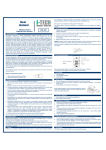
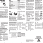
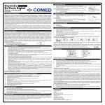
Pediatric Fingertip Pulse Oximeter 6 Item # 18707 Press the button again to toggle between six display modes. After turning on the Oximeter, each time you press the power switch, the Oximeter will switch to another display mode. There are 6 display modes shown as follows: 18707 USER MANUAL Ver4.0C5 General Description 1. 2. 3 4 5 6. Holding the power switch for longer than one second, will adjust the brightness of the oximeter. There are 10 levels of brightness. The default is level four. Front Panel Oxygen Saturation is a percentage of Oxyhemoglobin (HbO2) capacity, compounded with oxygen, by all combinative hemoglobin (Hb) capacity in blood. In other words, it is consistency of Oxyhemoglobin in blood. It is a very important parameter for the Respiratory Circulation System. Many respiratory diseases can result in oxygen saturation being lowered in human blood. Additionally, the following factors can reduce oxygen saturation: Automatic regulation of organ dysfunction caused by Anesthesia, Intensive Postoperative Trauma, injuries caused by some medical examinations. That situation might result in light-headedness, asthenia, and vomiting. Therefore, it is very important to know the oxygen saturation of a patient so that doctors can find problems in a timely manner. The fingertip pulse oximeter features low power consumption, convenient operation and portability. Place one fingertip into the photoelectric sensor for diagnosis and the pulse rate and oxygen saturation will appear on the display. It has been proven in clinical experiments that it also features high precision and repeatability. Measurement Principle Principle of the oximeter is as follows: A mathematical formula is established making use of Lambert Beer Law according to Spectrum Absorption Characteristics of Reductive hemoglobin (RHb) and Oxyhemoglobin (HbO2) in red and near-infrared zones. Operation principle of the instrument: Photoelectric Oxyhemoglobin Inspection Technology is adopted in accordance with Capacity Pulse Scanning and Recording Technology, so that two beams of different wavelength of lights (660nm red and 940nm near infrared light) can be focused onto a human nail tip through a clamping finger-type sensor. A measured signal obtained by a photosensitive element, will be shown on the oximeter’s display through process in electronic circuits and microprocessor. Diagram of Operation Principle 1. Red and Infrared-ray Emission Tube 2. Red and Infrared-ray Receipt Tube The height of the bar graph indicates of the pulse and signal strength. The bar should be greater than 30% for a proper reading. Product Accessories 1. 2. 3. 4. 5. Battery Installation 1. Install two AAA batteries into the battery compartment. Match the plus (+) and minus (-) signs in the compartment. If the polarities are not matched, damage may be caused to the oximeter. 2. Slide the battery door cover horizontally along the arrow shown as the picture. Precautions For Use 1 2 3 4 5 6 7 8 9 10 11 12 13 14 15 16 17 Before use, carefully read the manual. Operation of the fingertip pulse oximeter may be affected by the use of an electrosurgical unit (ESU). The fingertip pulse oximeter must be able to measure the pulse properly to obtain an accurate SpO2 measurement. Verify that nothing is hindering the pulse measurement before relying on the SpO2 measurement. Do not use the fingertip pulse oximeter in an MRI or CT environment. Do not use the fingertip pulse oximeter in situations where alarms are required. The device has no alarms. It is not for continuous monitoring. Do not use the fingertip pulse oximeter in an explosive atmosphere. The fingertip pulse oximeter is intended only as an adjunct in patient assessment. It must be used in conjunction with other methods of assessing clinical signs and symptoms. In order to ensure correct sensor alignment and skin integrity, the maximum application time at a single site for our device should be less than half an hour. Do not sterilize the device using autoclaving, ethylene oxide sterilizing, or immersing the device in liquid. The device is not intended for sterilization. Follow local ordinances and recycling instructions regarding disposal or recycling of the device and device components, including batteries. This equipment complies with IEC 60601-1-2:2007 for electromagnetic compatibility for medical electrical equipment and/or systems. However, because of the proliferation of radio-frequency transmitting equipment and other sources of electrical noise in healthcare and other environments, it is possible that high levels of such interference due to close proximity or strength of a source might disrupt the performance of this device. Portable and mobile RF communications equipment can affect medical electrical equipment. This equipment is not intended for use during patient transport outside the healthcare facility This equipment should not be used adjacent to or stacked with other equipment. Do not disassemble, repair or modify the equipment without authority. It may be unsafe to use accessories, detachable parts and materials not described in the instructions for use interconnect this equipment with other equipment not described in the instructions for use disassemble, repair or modify the equipment These materials that contact with the patient’s skin contain medical silicone and ABS plastic enclosure are all pass the ISO10993-5 Tests for invitro cytotoxicity and ISO10993-10 Tests for irritation and delayed-type hypersensitivity. Rx only: “Caution: Federal law (USA) restricts this device to sale by or on the order of a licensed practitioner.” Contraindication It is not for continuous monitoring. Inaccurate measurements may be caused by 1 2 3 4 5 6 7 8 9 10 11 12 Significant levels of dysfunctional hemoglobin (such as carbonyl - hemoglobin or methemoglobin). Intravascular dyes such as indocyanine green or methylene blue. High ambient light. Shield the sensor area if necessary. Excessive patient movement. High-frequency electrosurgical interference and defibrillators. Venous pulsations. Placement of a sensor on an extremity with a blood pressure cuff, arterial catheter, or intravascular line. The patient has hypotension, severe vasoconstriction, severe anemia, or hypothermia. The patient is in cardiac arrest or is in shock. Fingernail polish or false fingernails. Weak pulse quality (low perfusion). Low hemoglobin. Product Properties 1. 2. 3. 4. 5. 6. 7. Simple to operate and convenient to carry. Small volume, light weight and low power consumption. OLED display SpO2, PR, and Pulse bar. Level 1-10 adjustable brightness. 6 display modes. 2pcs AAA-size alkaline batteries; battery-low indicator. When no or low signal is detected, the pulse oximeter will power off automatically in 8 seconds. Intended Use Fingertip pulse oximeter is a portable non-invasive device intended for spot-checking of oxygen saturation of arterial hemoglobin (SpO2) and pulse rate of pediatric patients in hospitals and hospital-type facilities. Operation Instructions 1 2 3 4 5 Install two AAA batteries according to the Battery Installation instructions. Place one of your fingers into the rubber opening of the pulse oximeter. Press the switch button one time on front panel to turn the pulse oximeter on. Keep your hands still for the reading. Do not shake your finger during the test. It is recommended that you do not move your body while taking a reading. Read the data from the display screen. One lanyard Two AAA batteries One user manual One silicone case One hang bag Note: Please remove the batteries if the pulse oximeter will not be used for long periods of time. Using the Lanyard 1. Thread thinner end of the lanyard through the hanging hole. 2. Thread thicker end of the lanyard through the threaded end before pulling it tightly. Warnings! 1. Keep the oximeter away from young children. Small items such as the battery door, battery, and lanyard are choking hazards. 2. Do not hang the lanyard from the device’s electrical wire. 3. Please notice that the lanyard which is tied to the oximeter may cause strangulation due to excessive length. Maintenance and Storage 1. 2. 3. 4. 5. 6. Replace the batteries in a timely manner when low voltage lamp is lighted. Clean surface of the fingertip oximeter before it is used in diagnosis for patients. Remove the batteries if the oximeter is not operated for a long time. It is best to store the product in -20 +55 and 93% humidity. Keep in a dry place. Extreme moisture may affect oximeter lifetime and may cause damage. Dispose of battery properly; follow any applicable local battery disposal laws. Cleaning the fingertip pulse oximeter Please use medical alcohol to clean the silicone touching the finger inside of Oximeter with a soft cloth dampened with 70% isopropyl alcohol. Also clean the being tested finger using alcohol before and after each test. Do not pour or spray liquids onto the oximeter, and do not allow any liquid to enter any openings in the device. Allow the oximeter to dry thoroughly before reuse. The use life of the device is five years when it is used for 15 measurements every day and 10 minutes per one measurement. Stop using and contact local service center if one of the following cases occurs: An error in the Possible Problems and solutions is displayed on screen. The oximeter cannot be powered on in any case and not the reasons of battery. There is a crack on the oximeter or damage on the display resulting readings cannot be identified; the spring is invalid; or the key is unresponsive or unavailable. A functional tester cannot be used to assess the accuracy of a pulse oximeter monitor or sensor. Clinical testing is used to establish the SpO2 accuracy. The measured arterial hemoglobin saturation value (SpO2) of the sensors is compared to arterial hemoglobin oxygen (SaO2) value, determined from blood samples with a laboratory CO-oximeter. The accuracy of the sensors in comparison to the CO-oximeter samples measured over the SpO2 range of 70%-100%. Accuracy data is calculated using the root-mean-squared (Arms value) for all subjects, per ISO 9919:2005, Medical Electrical Equipment Particular requirements for the basic safety and essential performance of pulse oximeter equipment for medical use. A functional tester is used to measure how accurately Fingertip Pulse Oximeter is reproducing the specified calibration curve and the PR accuracy. The model of functional tester is Index2 FLUKE simulator and the version is 2.1.3. Specifications 1. Display Type OLED display 2. SpO2 Display range: 0%~99% Measurement range: 70%~99% Accuracy: 70%~99%: ±3%; 0%~69% no definition Resolution: 1% 3. Pulse Rate Display range: 0bpm~254bpm Measure range: 30bpm~235bpm Accuracy: 30bpm~99bpm, ±2bpm; 100bpm~235bpm, ±2% Resolution: 1bpm 4. Probe LED Specifications Wavelength Radiant Power RED 660 2nm 1.8mW IR 940 10nm 2.0mW NOTE: The information about wavelength range can be especially useful to clinicians. 5. Power Requirements Two AAA alkaline Batteries Power consumption: Less than 30mA Battery Life: Two AAA 1.5V, 600mAh alkaline batteries could be continuously operated as long as 30 hours. 6. Environment Requirements Operation Temperature: 5 40 Storage Temperature: -20 55 Ambient Humidity: 80% no condensation in operation 93% no condensation in storage Atmosphere pressure: 86kPa 106kPa Oximeter (18707). b Over the frequency range 150 kHz to 80 MHz, fields strengths should be less than 3 V/m Recommended separation distances between portable and mobile RF communications equipment and the EQUIPMENT or SYSTEMS - For all EQUIPMENT and SYSTEMS that are not LIFE-SUPPORTING Recommended separation distances between portable and mobile RF communications equipment and Pulse Oximeter (18707) The Pulse Oximeter (18707) is intended for use in electromagnetic environment in which radiated RF disturbances are controlled. The customer or the user of the Pulse Oximeter (18707) can help prevent electromagnetic interference by maintaining a minimum distance between portable and mobile RF communications equipment (transmitters) and the Pulse Oximeter (18707) as recommended below, according to the maximum output power of the communications equipment. Rated maximum output Separation distance according to frequency of transmitter (m) power of transmitter (W) 7. Equipment Response Time As shown in the right figure. Response time of slower average is 12.4s. 80 MHz to 800 MHz 800 MHz to 2.5 GHz 0.01 0.1167 0.2334 0.1 0.3689 0.7378 1 1.1667 2.3334 10 3.6893 7.3786 100 11.6667 23.3334 For transmitters rated at a maximum output power not listed above, the recommended separation distanced in meters (m) can be estimated using the equation applicable to the frequency of the transmitter, where P is the maximum output power rating of the transmitter in watts (W) according to the transmitter manufacturer. NOTE 1 At 80 MHz and 800 MHz, the separation distance for the higher frequency range applies. NOTE 2 These guidelines may not apply in all situations. Electromagnetic propagation is affected by absorption and reflection from structures, objects and people. Possible Problems and Solutions Problems SpO2 or PR cannot be shown normally 8. Classification According to the type of protection against electric shock: INTERNALLY POWERED EQUIPMENT; According to the degree of protection against electric shock: TYPE BF APPLIED PART; According to the degree of protection against ingress of water: IPX1 According to the mode of operation: CONTINUOUS OPERATION Declaration Guidance and Manufacturer’s declaration – electromagnetic emissions-For all EQUIPMENT and SYSTEMS Guidance and Manufacturer’s declaration - electromagnetic emission The 18707 Pulse Oximeter is intended for use in the electromagnetic environment specified below. The customer or the user of 18707 Pulse Oximeter should assure that it is used in such an environment. Emission test Compliance Electromagnetic Environment – guidance RF emissions CISPR 11 Group 1 The 18707 Pulse Oximeter uses RF energy only for its internal function. Therefore, its RF emissions are very low and are not likely to cause any interference in nearby electronic equipment. RF emissions CISPR 11 Class B The pulse Oximeter (18707) is suitable for use in all establishments, including domestic establishments and Harmonic emissions Not Applicable those directly connected to the public low-voltage power IEC 61000-3-2 supply network that supplies buildings used for domestic Voltage fluctuations/ flicker emissions Not Applicable purposes. IEC 61000-3-3 Guidance and Manufacturer’s declaration – electromagnetic immunity-For all EQUIPMENT and SYSTEMS Guidance and Manufacturer’s declaration - electromagnetic immunity The 18707 Pulse Oximeter is intended for use in the electromagnetic environment specified below. The customer or the user of the 18707 Pulse Oximeter should assure that it is used in such an environment. Immunity test IEC 60601 test Compliance Electromagnetic Environment – guidance level Level Electrostatic +/- 6kV contact +/- 6kV contact Floors should be wood, concrete or ceramic tile. If Discharge (ESD) +/- 8kV air +/- 8kV air floor are covered with synthetic material, the relative IEC 61000-4-2 humidity should be at least 30%. Power frequency (50/60 Hz) 3A/m 3A/m Power frequency magnetic fields should be at levels magnetic field characteristics of a typical location in a typical IEC 61000-4-8 commercial or hospital environment. Guidance and Manufacturer’s declaration – electromagnetic immunityFor all EQUIPMENT and SYSTEMS that are not LIFE-SUPPORTING Guidance and Manufacturer’s declaration - electromagnetic immunity The 18707 Pulse Oximeter is intended for use in the electromagnetic environment specified below. The customer or the user of the 18707 Pulse Oximeter should assure that it is used in such an environment. Immunity IEC 60601 Compliance Electromagnetic Environment – guidance test test level Level Portable and mobile RF communications equipment should be used no closer Radiated 3 V/m 3 V/m to any part of the Pulse Oximeter (18707), including cables, than the RF 80 MHz to recommended separation distance calculated from the equation applicable to IEC 2.5 GHz the frequency of the transmitter. 61000-4-3 Recommended separation distance 80 MHz to 800 MHz 800 MHz to 2.5 GHz Where P is the maximum output power rating of the transmitter in watts (W) according to the transmitter manufacturer and d is the recommended separation distance in meters (m). Field strengths from fixed RF transmitters, as determined by an electromagnetic site surveya, should be less than the compliance level in each frequency range. b Interference may occur in the vicinity of equipment marked with following symbol: NOTE 1 At 80 MHz and 800 MHz, the higher frequency range applies. NOTE 2 These guidelines may not apply in all situations, Electromagnetic propagation is affected by absorption and reflection structures, objects and people. a Field strengths from fixed transmitters, such as base station for radio (cellular/cordless) telephones and land mobile radios, amateur radio, AM and FM radio broadcast and TV broadcast cannot be predicted theoretically with accuracy. To assess the electromagnetic environment due to fixed RF transmitters, an electromagnetic site survey should be considered. If the measured field strength in the location in which the Pulse Oximeter (18707) should be observed to verify normal operation. If abnormal performance is observed, additional measurements may be necessary, such as reorienting of the relocating the Pulse Possible reason 1. Finger is not inserted correctly 2. Patient’s SpO2 value is too low to be measured SpO2 or PR is shown 1. Finger might not be inserted deep enough. 2. Excessive patient movement unstable The oximeter cannot 1. No battery or low power of battery 2. Batteries might be installed incorrectly be powered on 3. The oximeter might be damaged Indication lamps are suddenly off “Error3” or “Error4” is displayed on screen Error 6 “Error7” is displayed on screen Solution 1. Retry by inserting the finger 2. There is excessive illumination 3. Try some more times. If you can make sure no problem exist in the product, please go to a hospital timely for exact diagnosis. 1. Retry by inserting the finger 2. Remain calm 1. Please replace batteries 2. Please reinstall the batteries 3. Please contact with local customer service centre 1. The product is automatically powered off when no signal is detected longer than 8 seconds 2. The battery power is too low to work 1. Err 3 means the red emission LED is damaged 2. Err 4 means the infra-red emission LED is damaged 1. Normal 2. Replace the batteries Err 6 means the screen is failure Err 7 means all the emission LED or reception diode is damaged. Change the screen Check the emission LED and reception diode. 1. Check the red emission LED 2. Check the infra-red emission LED Symbol Definitions Symbol Definition Type BF applied part. Caution Follow instructions for use Protected against dripping water. SpO2 PR bpm Oxygen saturation Pulse rate (BPM) Low power indication No SpO2 Alarm SN Serial No. Storage temperature and relative humidity Manufacturer’s information Date of Manufacture Applicable Models 18707 187071 187072 187073 187074 Notes: The illustrations used in this manual may differ slightly from the appearance of the actual product. The specifications are subject to change without prior notice. Warranty Clause Your Drive brand product is warranted to be free of defects in materials and workmanship for two years from the original purchase date. The device was built to exacting standards and carefully inspected prior to shipment. This 2 year Limited Liability warranty is an expression of our confidence in the materials and workmanship of our products and our assurance to the consumer of years of dependable service. In the event of a defect covered by this warranty, we will, at our option, repair or replace the device. This warranty does not cover device failure due to owner misuse or negligence, or normal wear and tear. If you have questions about your Drive device, or this warranty, please contact an authorized Drive Medical provider. Distributed by: Drive Medical Design & Manufacturing 99 Seaview Boulevard Port Washington, NY 11050 www.drivemedical.com Local: 516-998-4600 Toll Free: 877-224-0946