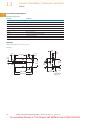
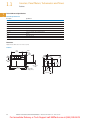
1
1.1
1
Counters, Panel Meters, Tachometers and Timers
Totalizers
Contents
Totalizers
Description
1
Page
Totalizers
Product Selection Guide . . . . . . . . . . . . . . . . . . . . . . . .
Mechanical
Stroke . . . . . . . . . . . . . . . . . . . . . . . . . . . . . . . . . . . . .
Revolution . . . . . . . . . . . . . . . . . . . . . . . . . . . . . . . . . .
Electromechanical . . . . . . . . . . . . . . . . . . . . . . . . . . . . .
Electronic . . . . . . . . . . . . . . . . . . . . . . . . . . . . . . . . . . . .
1
1
1
1
3
5
14
29
41
Learn
Online
1
1
1
1
1
1
1
1
1
1
1
1
1
1
1
1
Product Overview
Totalizers are used in a wide
variety of applications where
accurate totals are needed.
Typical applications include
counting the number of parts
produced, amount of material
used, or the number of
machine cycles occurring.
Totalizers are the simplest
and most common type of
counter. As an added bonus,
some models can perform
both totalizing and ratemeter
functions.
Application Example
Limit Switch
T/R
Durant ®
RST
Finished Parts
Limit Switch
Manufacturing
Process
Typical Application
Parts are fed into a machine
or process, an operation is
performed, and the finished
parts exit the machine or
process. The subtract
totalizer is used to indicate
the number of parts in
process.
Raw Parts
1
1
1
1
1
1
1
1
2
Volume 13—Counters, Timers and Tachometers CA08100015E—March 2011 www.eaton.com
For Immediate Delivery or Tech Support call KMParts.com at (866) 595-9616
Counters, Panel Meters, Tachometers and Timers
Totalizers
1.1
Product Selection Guide
1
Totalizers
Mechanical
Characteristics
Typical Applications
Various size ranges for different duty cycles and
environments
Winding and spooling equipment
No power supply needed
Mechanical piece/cycle counting
Position display
Panel Cutout
in Inches (mm)
Various mounting
configurations
1
Page
1
5
1
Long life and always readable display
1
1
Electromechanical
Various price, voltage and size ranges for different
duty cycles and environments
Coin-operated equipment
Long life and always readable display
Printing presses
Gaming machines
Various mounting
configurations
1
29
1
1
Secondary machines (e.g. punch press)
1
E5-024-C
Non-replaceable battery (min. eight-year life)
Replacement for mechanical counters
Compact, low cost and high efficiency
Transaction counting
Eight-digit LCD totalizers
Parts counting
Manual or electrical reset
Position indication or measurement
0.870 x 1.772
(22 x 45)
1
42
1
1
Various counting modes/inputs
E5-_24-E
Compact device with bright, LED display
Multiple functions available: count, time, rate,
multifunction, double-function
Count, measure, time where small package and
easy-to-read display required
0.870 x 1.772
(22 x 45)
1
44
Position display
24 Vdc Power
Motor/pulley RPM
Replaceable lithium battery
Eight-digit, high-visibility LCD display
Portable/mobile/remote flow monitoring
(e.g. sewer pumping, pesticide application)
Optional backlighting
Position display, RPM
Various input options available
Length measurement (e.g. carpet, cable)
Economical, multifunction display
Large, easy-to-read display
Large, LED characters
Position display
AC or DC power options
Motor/pulley RPM
1
1
Courier
E5-496-E
1.299 x 2.677
(33 x 68)
46
1
1
1.772 x 3.780
(45 x 96)
1
49
1
1
Eclipse
Six-digit, super bright LED display
Length measurement and control
Multiple models available: totalizers, ratemeters,
count controls, digital panel meters and flow controls
Flow monitoring and control
1.772 x 3.780
(45 x 96)
51
1
Process monitoring and display
1
Voltage and current monitoring and display
1
1
1
1
1
1
1
Volume 13—Counters, Timers and Tachometers CA08100015E—March 2011 www.eaton.com
For Immediate Delivery or Tech Support call KMParts.com at (866) 595-9616
3
1.1
Totalizers
Totalizers, continued
1
1
Counters, Panel Meters, Tachometers and Timers
President
1
Characteristics
Typical Applications
Bright LED display with 14 mm characters
Cut-to-length machinery with batching
Simple configuration with 14-button tactile keypad
Parts batching/palletizing
Many different versions fit almost any application
Die press positioning control
Page
2.667 x 5.433
(68 x 138)
54
2.667 x 2.667
(68 x 68)
58
1.988 (50.5) dia. or
DIN rail
112
Applications where parameter changes are required
1
1
Panel Cutout
in Inches (mm)
Ambassador
Eight-digit, high-visibility, two-line LCD display
User-configurable control inputs
1
Flow control where simultaneous total and rate
display are required
Highly flexible control/display
Cut-to-length and other simple processes where
flexibility of inputs/outputs required
Combination counter consists of time meter and
adding counter in one
General counting
1
Hour Meter/Counter
1
High shock resistance
Service interval for measurement systems
(respiratory ventilators, oxygen machines,
dialysis machines)
Magnified figures
Small appliances
Protection IP52 (front)
UV lamps
Data retention if power is lost
Display panels in cars
Without reset
1
1
1
Long service life
UL approved
1
1
1
1
1
1
1
1
1
1
1
1
1
1
1
1
1
1
1
4
Volume 13—Counters, Timers and Tachometers CA08100015E—March 2011 www.eaton.com
For Immediate Delivery or Tech Support call KMParts.com at (866) 595-9616
Counters, Panel Meters, Tachometers and Timers
Totalizers
1.1
Contents
Mechanical Totalizers (Stroke)
Description
Mechanical Totalizers (Stroke)
X Series/Pushbutton Desk Tally—Durant® . . . . . . . . . . .
CS Series—Durant® . . . . . . . . . . . . . . . . . . . . . . . . . . . .
H Series—Durant® . . . . . . . . . . . . . . . . . . . . . . . . . . . . .
D Series—Durant® . . . . . . . . . . . . . . . . . . . . . . . . . . . . .
Mechanical Totalizers (Revolution) . . . . . . . . . . . . . . . . . . .
Electromechanical Totalizers . . . . . . . . . . . . . . . . . . . . . . . .
Electronic Totalizers . . . . . . . . . . . . . . . . . . . . . . . . . . . . . . .
Page
1
1
6
8
10
12
14
29
41
1
1
1
1
1
1
1
1
1
Mechanical Totalizers (Stroke)
Product Overview
Features
Eaton’s mechanical totalizers
are available in a variety of
heavy-duty configurations for
applications when power is
unavailable.
●
●
1
Variety of reset methods
available
Accurate counting without
need for power
1
1
1
1
1
1
1
1
1
1
1
1
1
1
1
1
1
1
Volume 13—Counters, Timers and Tachometers CA08100015E—March 2011 www.eaton.com
For Immediate Delivery or Tech Support call KMParts.com at (866) 595-9616
5
1.1
1
1
1
1
1
1
1
Counters, Panel Meters, Tachometers and Timers
Totalizers
X Series/Pushbutton Desk Tally—Durant ®
Product Description
X Series Counters
Model X Series is a dustproof
and rustproof series of
counters for light and
medium-duty work. They are
sound and durable, requiring
a minimum of driving effort,
and have been especially
designed for incorporation as
integral parts of a variety of
machines and equipment.
Pushbutton Desk Tally
Ruggedly constructed
counters with feather-touch
pushbutton operation and
maximum readability.
Specifications and
dimensions are basically the
same as the X Series
counters. Will give long and
accurate service in areas
requiring hand counting or
during hand operations.
1
1
1
1
1
Product Selection
When Ordering Specify
To determine a model
number from the Product
Selection table for Model X
X Series Stroke
Counter
Series Stroke Counters and
Pushbutton Desk Tallies,
consider:
●
●
Number of figures
Drive
X Series Stroke Counters and Pushbutton Desk Tallies
No. of
Figures
Drive
Reset
Mounting
Catalog Number
Order
Number
1
4
LH lever
Knob
Base
4-X-1-1-L
40263400
5
LH lever
Knob
Base
5-X-1-1-L
40272401
1
4
RH lever
Knob
Base
4-X-1-1-R
40263401
5
RH lever
Knob
Base
5-X-1-1-R
40272402
4
LH lever
Knob
Base
4-X-1-1-L-REV 40263403
4
RH lever
Knob
Base
4-X-1-1-R-REV 40263402
5
LH lever
Knob
Base
5-X-1-1-L-REV 40272400
1
5
RH lever
Knob
Base
5-X-1-1-R-REV 40272403
4
Push bar
Knob
Base
4-X-2
21619400
1
4
Pushbutton
Knob
Base
4-X-2-A
33245400
1
1
Pushbutton Desk Tally
1
1
1
Note
Reverse stroke.
1
1
1
1
1
1
1
1
1
6
Volume 13—Counters, Timers and Tachometers CA08100015E—March 2011 www.eaton.com
For Immediate Delivery or Tech Support call KMParts.com at (866) 595-9616
Counters, Panel Meters, Tachometers and Timers
Totalizers
1.1
Technical Data and Specifications
1
General Specifications
Description
Specification
Figures
4 or 5
Speed
1000 cpm
1
1
Shaft
0.125 in (3.2 mm) diameter stainless steel
Drive
Drive parts of nylon
Bearings
Oil-less, maintenance free
Finish
Black frame and Cycolac black cover
Stroke operation
33° minimum; 58° maximum 1
1
1
Figure size
3/16 in (4.8 mm) high, white-on-black background
Reset
Knob
1
1
1
Dimensions
Approximate Dimensions in Inches (mm)
1
X Series
C
0.14
(3.6)
Pre
Stroke
0.97 1.20 1.44
(24.6) (30.6) (36.5)
0.12
(3.2)
0.53 (13.5)
1
1
12° ±5°
45° ±5°
0.44 (11.1)
A
B
1
0.89
(22.6)
1.38 (35.1)
D
58° ±5°
1
Dia. 0.093
(2.36)
Index Stroke
1
Total Stroke
1
Model
A
B
C
D
4-X-1-1_
1.86 (47.2)
2.76 (70.2)
0.62 (15.7)
0.89 (22.6)
5-X-1-1_
2.16 (54.8)
3.06 (77.8)
0.81 (20.6)
0.95 (24.1)
1
1
Note
Operating stroke angles apply to forward stroke counter only. Check factory for angles of reverse stroke counter.
1
1
1
1
1
1
1
1
1
1
1
1
Volume 13—Counters, Timers and Tachometers CA08100015E—March 2011 www.eaton.com
For Immediate Delivery or Tech Support call KMParts.com at (866) 595-9616
7
1.1
1
1
1
1
1
1
1
1
1
1
1
Counters, Panel Meters, Tachometers and Timers
Totalizers
CS Series—Durant ®
Product Description
Model CS Series of small,
compact, top reading stroke
counters is designed for
use in most industrial
applications. These counters
are ruggedly built and feature
a single casting case, which
assures great rigidity and a
tight seal for working parts.
Product Selection
When Ordering Specify
To determine a model
number from the Product
Selection table for Model CS
CS Series Stroke
Counter
1
1
1
Series Stroke Counters,
consider:
●
●
Number of figures
Drive lever
CS Series Stroke Counters
No. of
Figures
Drive
Reset
Mounting
Catalog Number
Order
Number
4
RH lever
Wing nut
Base
4-CS-1-1-R
31062400
5
RH lever
Wing nut
Base
5-CS-1-1-R
31062401
5
LH lever
Wing nut
Base
5-CS-1-1-L
31061401
5
RH lever
Wing nut
Base
5-CS-1-1-R-RP 01464400
5
LH lever
Wing nut
Base
5-CS-1-1-L-RP 00445400
1
1
1
1
1
Technical Data and Specifications
General Specifications
Description
Specification
Figures
4 or 5
Speed
600 cpm
1
Stroke operation
37-1/2° minimum; 75° maximum
Shaft
0.25 in (6.4 mm) diameter stainless steel, rustproof
1
Drive
Accurately machined, hardened steel parts
Bearings
Oil-less, maintenance free
1
Figure size
11/32 in (8.7 mm) high, black-on-white background
1
Reset
Contoured wing nut
Finish
Black frame
1
Operating lever
Cast zinc. Adjustable to any position. Furnished complete with pull spring.
1
Note
Special feature: rustproof.
1
1
1
1
1
8
Volume 13—Counters, Timers and Tachometers CA08100015E—March 2011 www.eaton.com
For Immediate Delivery or Tech Support call KMParts.com at (866) 595-9616
Counters, Panel Meters, Tachometers and Timers
Totalizers
1.1
Dimensions
Approximate Dimensions in Inches (mm)
1
CS Series
1
1
Dia. 0.156
4 Mtg. Holes
0.47
(11.9)
0.73
(18.6)
D
1
0.42
(10.7)
1
1
Stroke
37.5° Min. – 75° Max.
0.50 (12.7)
0.92
(23.4)
1
1
1.25
(31.8)
1.34
(34.1)
Dia. 0.25
(6.35)
1.19
(30.2)
A
B
C
0.56
(14.3)
1
2.09
(53.1)
1
1
0.22
(5.6)
1.25
(31.8)
1.69 (42.9)
1.00
(25.4)
1
1
Model
A
B
C
D
4-CS-1_
3.12 (79.2)
3.50 (88.9)
4.03 (102.3)
1.87 (47.6)
5-CS-1_
3.62 (91.9)
4.00 (101.6)
4.53 (115.0)
2.38 (60.5)
1
1
1
1
1
1
1
1
1
1
1
1
1
1
1
1
1
Volume 13—Counters, Timers and Tachometers CA08100015E—March 2011 www.eaton.com
For Immediate Delivery or Tech Support call KMParts.com at (866) 595-9616
9
1.1
1
1
1
1
1
1
Counters, Panel Meters, Tachometers and Timers
Totalizers
H Series—Durant ®
Product Description
Model H Series heavy-duty
counters are designed for
hard usage and long, troublefree service. They are high
speed, streamlined counters
constructed of the highest
quality materials and drive
shaft moves in oil-less
bearings. All shafts are
stainless steel. The drive
action is designed with
overstroke so counter does
not bottom, increasing life
and permitting easier
installation. The sturdy cover
is stamped steel, locked into
position on a heavy, die-cast
base of a special alloy. A
heavy steel mounting plate is
adjustable for either bottom
or back mounting. Model “H”
has earned the reputation of
being the “work horse” of
industrial counters. Wing nut
or tamper-proof reset lock
which requires a key to reset
the counter, guarding against
unauthorized resetting or
tampering.
1
1
1
1
1
1
Product Selection
When Ordering Specify
To determine a model
number from the Product
Selection table for Model H
Series Stroke Counters,
consider:
H Series Stroke
Counter
1
1
1
1
1
●
●
Number of figures
Drive lever location
(left or right side)
●
Type of reset
(lock or wing nut)
H Series Stroke Counters
No. of
Figures
Drive
5
RH lever
5
LH lever
5
RH lever
Wing nut
Reset
Order
Number
Mounting
Catalog Number
Wing nut
Base
5-H-1-1-R
40205400
Wing nut
Base
5-H-1-1-L
40205401
Base
5-H-1-1-R-REV 00597400
00598400
5
LH lever
Wing nut
Base
5-H-1-1-L-REV
5
RH lever
Wing nut
Base
5-H-1-1-R-RP 5
LH lever
Wing nut
Base
5-H-1-1-L-RP 40205405
5
RH lever
Lock reset
Base
5-H-1-2-R
40206404
40205404
5
LH lever
Lock reset
Base
5-H-1-2-L
40206405
5
RH lever
Lock reset
Base
5-H-1-2-R-RP 40206400
5
RH lever
Lock reset
Base
5-H-1-2-L-RP 40206401
1
5
RH lever
Wing nut
Rear
5-H-1-4-R
00507400
1
5
LH lever
Wing nut
Rear
5-H-1-4-L
00508400
5
RH trip arm
Wing nut
Base
5-H-5-A
31049400
1
1
1
1
1
1
5
RH trip arm
Wing nut
Base
5-H-5-B
31049401
5
LH trip arm
Wing nut
Base
5-H-5-C
31049402
5
LH trip arm
Wing nut
Base
5-H-5-D
31049403
5
RH trip arm
Lock reset
Base
5-H-6-A
01533400
5
RH trip arm
Lock reset
Base
5-H-6-B
01534400
5
LH trip arm
Lock reset
Base
5-H-6-C
01535400
5
LH trip arm
Lock reset
Base
5-H-6-D
01536400
Notes
Special feature: Reverse stroke.
Special feature: Rustproof.
1
1
1
1
1
10
Volume 13—Counters, Timers and Tachometers CA08100015E—March 2011 www.eaton.com
For Immediate Delivery or Tech Support call KMParts.com at (866) 595-9616
Counters, Panel Meters, Tachometers and Timers
Totalizers
1.1
Technical Data and Specifications
1
Direction Location for 5H5 and 5H6
1
1
C
A
1
B
1
D
1
1
General Specifications
Description
Specification
Figures
5
Speed
800 cpm
1
1
Stroke operation
37° stroke to count; 60° maximum stroke
Shaft
0.31 in (7.9 mm) diameter stainless steel, rustproof
1
Drive
Accurately machined, hardened steel parts; Geneva drive for extra long life
Bearings
Oil-less, maintenance free
1
1
Figure sizes
11/32 in (8.7 mm) high, black-on-white background
Reset
Wing nut or tumbler lock reset
Finish
Black frame and cover
Operating lever
Adjustable to any position. Furnished complete with pull spring for attaching.
1
1
1
Dimensions
Approximate Dimensions in Inches (mm)
1
H Series
1
Lock Reset
1.20
(30.6)
0.98
(25.0)
C
0.75
(19.1)
1
0.75
(19.1)
1
2.76
(70.1)
0.91
(23.0)
Dia. 0.31
(7.92)
A
1
1.0
(25.4)
1.80
(45.7)
B
1
1.12
(28.4)
1
2.25 (57.2)
1
Model
A
B
C
Five figure units
3.95 (100.4)
4.38 (111.3)
2.75 (69.9)
1
1
1
1
1
1
1
Volume 13—Counters, Timers and Tachometers CA08100015E—March 2011 www.eaton.com
For Immediate Delivery or Tech Support call KMParts.com at (866) 595-9616
11
1.1
1
1
1
1
Counters, Panel Meters, Tachometers and Timers
Totalizers
D Series—Durant ®
Product Description
Model D Series are mediumduty stroke counters available
with 4, 5 or 6 figures that
have been designed for
general service on small
production machines.
Although compact, Durant®
“D” models are sturdily
constructed and thoroughly
tested for accuracy and
efficient operation.
1
1
Product Selection
1
When Ordering Specify
To determine a model
number from the Product
Selection table for Model D
1
1
1
D Series Stroke
Counter
1
Series Stroke Counters,
consider:
●
●
Number of figures
Drive lever
D Series Stroke Counters
No. of
Figures
Drive
Reset
Mounting
Catalog Number
Order
Number
4
RH lever
Wing nut
Base
4-D-1-1-R
34269401
5
RH lever
Wing nut
Base
5-D-1-1-R
34269402
1
6
RH lever
Wing nut
Base
6-D-1-1-R
34269403
4
LH lever
Wing nut
Base
4-D-1-1-L
34269405
1
5
LH lever
Wing nut
Base
5-D-1-1-L
34269406
6
LH lever
Wing nut
Base
6-D-1-1-L
34269407
1
1
1
1
1
1
Technical Data and Specifications
General Specifications
Description
Specification
Figures
4, 5 and 6
Speed
400 cpm
Shaft
0.25 in (6.4 mm) diameter stainless steel, rustproof
Drive
Nylon rachet and Delrin drive plate. Right-hand drive standard; left-hand drive available
Bearings
Oil-less, maintenance free
1
Figure size
1/4 in (6.4 mm) high, black-on-white background
Reset
Wing nut
1
Finish
Black frame and cover
Operating lever
Adjustable to any position. Furnished complete with pull string
1
1
1
1
1
1
1
1
1
12
Volume 13—Counters, Timers and Tachometers CA08100015E—March 2011 www.eaton.com
For Immediate Delivery or Tech Support call KMParts.com at (866) 595-9616
Counters, Panel Meters, Tachometers and Timers
Totalizers
1.1
Dimensions
Approximate Dimensions in Inches (mm)
1
D Series
1
C
1
0.62 (15.7)
1.72
(43.6)
1
Dia. 0.12
(3.05)
4 Mtg.
Holes
1.25
(31.8)
1
1
0.50
(12.7)
A
1.62 (41.3)
B
1.87 (47.6)
Model
A
B
C
4-D-1-1_
1.59 (40.4)
2.20 (55.9)
1.20 (30.6)
5-D-1-1_
1.92 (48.8)
2.53 (64.3)
1.51 (38.5)
6-D-1-1_
2.26 (57.5)
2.87 (73.0)
1.83 (46.4)
1
1
1
1
1
1
1
1
1
1
1
1
1
1
1
1
1
1
1
1
1
1
1
1
Volume 13—Counters, Timers and Tachometers CA08100015E—March 2011 www.eaton.com
For Immediate Delivery or Tech Support call KMParts.com at (866) 595-9616
13
1.1
1
Counters, Panel Meters, Tachometers and Timers
Totalizers
Contents
Mechanical Totalizers (Revolution)
Description
1
Mechanical Totalizers (Stroke) . . . . . . . . . . . . . . . . . . . . . . .
Mechanical Totalizers (Revolution)
X Series—Durant® . . . . . . . . . . . . . . . . . . . . . . . . . . . . .
CS Series—Durant® . . . . . . . . . . . . . . . . . . . . . . . . . . . .
D-7 Series—Durant® . . . . . . . . . . . . . . . . . . . . . . . . . . .
D-6 Series—Durant® . . . . . . . . . . . . . . . . . . . . . . . . . . .
HDW Series—Durant® . . . . . . . . . . . . . . . . . . . . . . . . . .
T Series—Durant® . . . . . . . . . . . . . . . . . . . . . . . . . . . . .
H Series—Durant® . . . . . . . . . . . . . . . . . . . . . . . . . . . . .
Electromechanical Totalizers . . . . . . . . . . . . . . . . . . . . . . . .
Electronic Totalizers . . . . . . . . . . . . . . . . . . . . . . . . . . . . . . .
1
1
1
1
1
Page
5
15
17
19
21
23
25
27
29
41
1
1
1
1
Mechanical Totalizers (Revolution)
1
Product Overview
Features
Eaton’s mechanical totalizers
are available in a variety of
heavy-duty configurations for
applications when power is
unavailable.
●
1
1
1
●
Variety of reset
configurations available
Accurate length
measurement for
application where
power is not available
1
1
1
1
1
1
1
1
1
1
1
1
1
1
1
14
Volume 13—Counters, Timers and Tachometers CA08100015E—March 2011 www.eaton.com
For Immediate Delivery or Tech Support call KMParts.com at (866) 595-9616
Counters, Panel Meters, Tachometers and Timers
Totalizers
1.1
X Series—Durant ®
1
Product Description
1
They are especially designed
for incorporation as integral
parts of a variety of equipment
that gets severe usage under
adverse climatic conditions.
Model X Series are dust- and
rust-proof counters designed
for small, medium-duty units,
accurate, durable and require
a minimum of driving effort.
1
1
1
Product Selection
1
When Ordering Specify
To determine a model
number from the Product
Selection table for Model X
X Series Revolution
Counter
Series Revolution Counters,
consider:
●
●
●
●
Number of figures
Ratio
Drive shaft location
Shaft rotation direction
1
1
X Series Revolution Counters
No. of
Figures
Drive
Rotation
Reset
Mounting
Catalog Number
Order
Number
4
LH
Clockwise Knob
Base
4-X-7-1-L-CL
40270406
5
LH
Clockwise Knob
Base
5-X-7-1-L-CL
40275404
4
LH
Anti-clockwise Knob
Base
4-X-7-1-L-AC
40270404
5
LH
Anti-clockwise Knob
Base
5-X-7-1-L-AC
40275407
4
RH
Clockwise
Knob
Base
4-X-7-1-R-CL
40270407
5
RH
Clockwise Knob
Base
5-X-7-1-R-CL
40275405
4
RH
Anti-clockwise Knob
Base
4-X-7-1-R-AC
40270405
5
RH
Anti-clockwise Knob
Base
5-X-7-1-R-AC
40275406
4
LH
Clockwise Knob
Base
4-X-7-1-L-CL 40270402
5
LH
Clockwise
Knob
Base
5-X-7-1-L-CL
40275402
4
LH
Anti-clockwise Knob
Base
4-X-7-1-L-AC 40270400
5
LH
Anti-clockwise
Knob
Base
5-X-7-1-L-AC
40275400
4
RH
Clockwise Knob
Base
4-X-7-1-R-CL 40270403
5
RH
Clockwise Knob
Base
5-X-7-1-R-CL 40275403
4
RH
Anti-clockwise Knob
Base
4-X-7-1-R-AC 40270401
5
RH
Anti-clockwise Knob
Base
5-X-7-1-R-AC 40275401
1
1
1
1
1
1
1
1
1
1
1
1
Top View—Left-Hand Drive
1
Clockwise Shaft Rotation
1
Anti-Clockwise Shaft Rotation
1
Top View—Right-Hand Drive
1
Clockwise Shaft Rotation
1
Anti-Clockwise Shaft Rotation
1
Notes
When shaft is turned in the reverse direction of rotation, the counter will subtract.
1
Top view—left-hand drive with clockwise shaft rotation.
Top view—left-hand drive with anti-clockwise shaft rotation.
Top view—right-hand drive with clockwise shaft rotation.
Top view—right-hand drive with anti-clockwise shaft rotation.
Special feature: 10:1 ratio.
1
1
1
Volume 13—Counters, Timers and Tachometers CA08100015E—March 2011 www.eaton.com
For Immediate Delivery or Tech Support call KMParts.com at (866) 595-9616
15
1.1
Counters, Panel Meters, Tachometers and Timers
Totalizers
1
Technical Data and Specifications
1
General Specifications
Description
Specification
1
Figures
4 or 5
Speed
1000 cpm in 1:1 ratio;
1
1
1
1
10,000 cpm in 10:1 ratio for intermittent duty
Rotation direction
Clockwise or anti-clockwise when viewed from right-hand end of counter
Ratio
1:1 and 10:1 standard in 4-X-7 models
10:1 standard in 5-X-7 models
Shaft
0.125 in (3.2 mm) diameter stainless steel; standard length 0.44 in (11.1 mm)
Bearings
Oil-less, maintenance free
Figure size
3/16 in (4.8 mm) high, white-on-black background
Reset
Knob
1
Finish
Black frame, Cycolac black cover
Drive
Right- or left-hand drive; drive parts of Delrin
1
Ratio information
1:1 is one count to each revolution of drive shaft, 10:1 is ten counts to each revolution
1
1
Dimensions
1
Approximate Dimensions in Inches (mm)
1
X Series
1
D
C
E
Dia. 0.12
(3.2)
1.38 (35.1)
0.14
(3.6)
1
1.20
(30.6)
1.44
(36.5)
CL
0.97
(24.6)
0.12
(3.2)
AC
1
1
0.53 (13.5)
1
A
B
1
1
1
0.45
(11.5)
0.44 (11.1)
Model
A
B
C
D
E
4-X-7-1_
1.86 (47.2)
2.76 (70.2)
0.62 (15.7)
0.19 (4.8)
0.89 (22.6)
5-X-7-1_
2.16 (54.8)
3.06 (77.8)
0.81 (20.6)
0.25 (6.4)
0.95 (24.1)
1
1
1
1
1
1
1
1
1
16
Volume 13—Counters, Timers and Tachometers CA08100015E—March 2011 www.eaton.com
For Immediate Delivery or Tech Support call KMParts.com at (866) 595-9616
Counters, Panel Meters, Tachometers and Timers
Totalizers
1.1
CS Series—Durant ®
1
Product Description
1
This provides greater rigidity,
tighter seal of working parts
and more streamlined
contour. The unit is compact,
rugged and features a flush
mounted window to assure
greater visibility.
Model CS Series top reading
revolution counters are
designed for use in most
industrial applications. The
entire case is a single casting.
1
1
1
1
Product Selection
1
When Ordering Specify
To determine a model
number from the Product
Selection table for Model CS
CS Series Revolution
Counter
Series Revolution
Counters, consider:
●
●
●
●
Number of figures
Ratio
Drive shaft location
Shaft rotation direction
1
1
CS Series Revolution Counters
No. of
Figures
Drive
Rotation
Reset
Mounting
Catalog Number
Order
Number
5
LH
Clockwise
Wing nut
Base
5-CS-7-1-L-CL
31060408
5
RH
Clockwise Wing nut
Base
5-CS-7-1-R-CL
31060409
5
LH
Anti-clockwise
Wing nut
Base
5-CS-7-1-L-AC
31060410
5
RH
Anti-clockwise Wing nut
Base
5-CS-7-1-R-AC
31060411
5
LH
Clockwise
Wing nut
Base
5-CS-7-1-L-CL 00440400
4
RH
Clockwise Wing nut
Base
4-CS-7-1-R-CL 31057401
5
RH
Clockwise Wing nut
Base
5-CS-7-1-R-CL 00441400
5
LH
Anti-clockwise
Wing nut
Base
5-CS-7-1-L-AC 00442400
4
RH
Anti-clockwise Wing nut
Base
4-CS-7-1-R-AC 31057403
5
RH
Anti-clockwise Wing Nut
Base
5-CS-7-1-R-AC 00443400
4
RH and LH
Clockwise None
Base
4-CS-7-3-CL 31057408
None
Base
4-CS-7-3-AC
31057409
None
Base
5-CS-7-3-CL 31057410
Base
31057411
4
RH and LH
Anti-clockwise
5
RH and LH
Clockwise 5
RH and LH
Anti-clockwise
None
5-CS-7-3-AC
1
1
1
1
1
1
1
1
1
1
1
Top View—Right-Hand Drive
1
Clockwise Shaft Rotation
1
Anti-Clockwise Shaft Rotation
1
Top View—Right- and Left-Hand Drive
1
Clockwise Shaft Rotation
Anti-Clockwise Shaft Rotation
1
Notes
When shaft is turned in the reverse direction of rotation, the counter will subtract.
1
1
Top view—right-hand drive with clockwise shaft rotation.
Top view—right-hand drive with anti-clockwise shaft rotation.
Special feature: 10:1 ratio.
Top view—right- and left-hand drive with clockwise shaft rotation.
Special feature: 10:1 ratio, non-reset, double shaft.
Top view—right- and left-hand drive with anti-clockwise shaft rotation.
1
1
1
Volume 13—Counters, Timers and Tachometers CA08100015E—March 2011 www.eaton.com
For Immediate Delivery or Tech Support call KMParts.com at (866) 595-9616
17
1.1
Counters, Panel Meters, Tachometers and Timers
Totalizers
1
Technical Data and Specifications
1
General Specifications
Description
Specification
1
Figures
4 or 5
Speed
600 cpm in 1:1 ratio
Rotation direction
Clockwise or anti-clockwise when viewed from right-hand end of counter
1
Ratio
1:1 standard
Shaft
0.25 in (6.4 mm) diameter stainless steel; standard length 1 in (25.4 mm)
1
Drive
Spur gear
Bearings
Oil-less, maintenance free
1
Figure size
11/32 in (8.7 mm) high, black-on-white background
Reset
Contoured wing nut
Finish
Black frame
1
1
1
1
1
1
1
Dimensions
Approximate Dimensions in Inches (mm)
CS Series
Dia. 0.156 (3.96)
4 Mtg. Holes
D
0.73
(18.6)
0.42
(10.7)
1
1
0.50 (12.7)
0.92 (23.4)
1
1
Dia. 0.25
(6.4)
2.09
(53.1)
1
1.34
(34.1)
1
A
B
C
1
1
1.19
(30.2)
0.22
(5.6)
1.00
(25.4)
1.25
(31.8)
1.69 (42.9)
0.56
(14.3)
1
Model
4-CS-7_
3.12 (79.2)
3.50 (88.9)
4.03 (102.3)
1.89 (47.9)
1
5-CS-7_
3.62 (91.9)
4.00 (101.6)
4.53 (115.0)
2.38 (60.5)
A
B
C
D
1
1
1
1
1
1
1
18
Volume 13—Counters, Timers and Tachometers CA08100015E—March 2011 www.eaton.com
For Immediate Delivery or Tech Support call KMParts.com at (866) 595-9616
Counters, Panel Meters, Tachometers and Timers
Totalizers
1.1
D-7 Series—Durant ®
1
Product Description
1
recommended for braiding
machines, low-speed coil
winders, wire measuring
equipment and all mediumduty revolution applications.
Model D-7 Series spur gear
end drive units are compact
counters that meet a variety
of needs. Accurate,
dependable and moderately
priced, they are especially
1
1
1
Product Selection
1
When Ordering Specify
To determine a model
number from the Product
Selection table for Model D-7
D-7 Series Revolution
Counter
Series Revolution Counters,
consider:
●
●
●
●
Number of figures
1
Shaft drive
Shaft rotation direction
Reset or non-reset
1
1
D-7 Series Revolution Counters
No. of
Figures
Drive
Rotation
Reset
Mounting
Catalog Number
Order
Number
5
LH
Clockwise Wing nut
Base
5-D-7-1-L-CL
31127408
5
LH
Anti-clockwise Wing nut
Base
5-D-7-1-L-AC
31127405
5
RH
Clockwise Wing nut
Base
5-D-7-1-R-CL
31127431
5
RH
Anti-clockwise Wing nut
Base
5-D-7-1-R-AC
31127400
5
LH
Clockwise None
Base
5-D-7-3-L-CL
31127416
5
LH
Anti-clockwise None
Base
5-D-7-3-L-AC
31127412
None
Base
5-D-7-3-R-CL
31127438
None
Base
5-D-7-3-R-AC
31127442
5
RH
Clockwise
5
RH
Anti-clockwise 1
1
1
1
1
1
1
Top View—Left-Hand Drive
1
Clockwise Shaft Rotation
1
Anti-Clockwise Shaft Rotation
1
Top View—Right-Hand Drive
1
Clockwise Shaft Rotation
1
Anti-Clockwise Shaft Rotation
1
Notes
When shaft is turned in the reverse direction of rotation, the counter will subtract.
1
Top view—left-hand drive with clockwise shaft rotation.
Top view—left-hand drive with anti-clockwise shaft rotation.
Top view—right-hand drive with clockwise shaft rotation.
Top view—right-hand drive with anti-clockwise shaft rotation.
1
1
1
1
1
1
1
Volume 13—Counters, Timers and Tachometers CA08100015E—March 2011 www.eaton.com
For Immediate Delivery or Tech Support call KMParts.com at (866) 595-9616
19
1.1
Counters, Panel Meters, Tachometers and Timers
Totalizers
1
Technical Data and Specifications
1
General Specifications
Description
Specification
1
Figures
5 standard
Speed
Up to 800 cpm in 1:1 ratio
Rotation direction
Clockwise or anti-clockwise when viewed from right-hand end of counter
Ratio
1:1 standard
Shaft
0.31 in (7.9 mm) diameter stainless steel; 0.66 in (16.7 mm) right-hand drive,
0.63 in (15.9 mm) left-hand drive
1
1
1
Drive
Right- or left-hand spur gear drive
1
Bearings
Oil-less, maintenance free
Figure size
1/4 in (6.4 mm) high, black-on-white background
1
Finish
Black frame and cover
Reset
Wing nut or non-reset
1
1
1
1
Dimensions
Approximate Dimensions in Inches (mm)
D-7 Series
1.51
(38.5)
1
0.75
(19.0)
0.12
(3.2)
1.17
(29.8)
1
Dia. 0.31
(7.9)
1
0.50
(12.7)
Dia. 0.120
(3.05)
4 Mtg.
Holes
1.72
(43.6)
1
1
1.92 (48.8)
1
0.50
(12.7)
2.53 (64.3)
0.78
(19.8)
1.62 (41.3)
1
1
1
1
1
1
1
1
1
1
1
1
20
Volume 13—Counters, Timers and Tachometers CA08100015E—March 2011 www.eaton.com
For Immediate Delivery or Tech Support call KMParts.com at (866) 595-9616
Counters, Panel Meters, Tachometers and Timers
Totalizers
1.1
D-6 Series—Durant ®
1
Product Description
1
adapted as accessory
equipment on machinery
where right-angle drive is
desired to permit full view
reading of the counter.
Model D-6 right-angle worm
drive counters are ruggedly
designed for high speeds on
light-duty applications. Small
“D” counters are easily
1
1
1
Product Selection
1
When Ordering Specify
To determine a model
number from the Product
Selection table for Model D-6
D-6 Series Revolution
Counter
Series Revolution Counters,
consider:
●
1
Shaft rotation direction
1
1
D-6 Series Revolution Counters
No. of
Figures
Drive
Rotation
Reset
Mounting
Catalog Number
Order
Number
1
5
Front and rear
Anti-clockwise Wing nut
Base
5-D-6-1-AC
31052401
6
Front and rear
Anti-clockwise Wing nut
Base
6-D-6-1-AC
31052402
1
5
Front and rear
Clockwise Wing nut
Base
5-D-6-1-CL
31052404
6
Front and rear
Clockwise Wing nut
Base
6-D-6-1-CL
31052405
5
Front and rear
Anti-clockwise Wing nut
Base
5-D-8-1-AC 40187401
6
Front and rear
Anti-clockwise Wing nut
Base
6-D-8-1-AC 40187402
5
Front and rear
Clockwise Wing nut
Base
5-D-8-1-CL 40187417
6
Front and rear
Clockwise Wing nut
Base
6-D-8-1-CL 40187418
5
Front and rear
Clockwise Wing nut
Base
5-D-9-1-CL 40187404
5
Front and rear
Anti-clockwise Wing nut
Base
5-D-9-1-AC 40187410
5
Front and rear
Clockwise
5
Front and rear
Anti-clockwise 40187414
40187408
Wing nut
Base
5-D-90-1-CL
Wing nut
Base
5-D-90-1-AC 1
1
1
1
1
1
1
Top View of Counter
1
1
1
Anti-Clockwise Shaft Rotation
1
Clockwise Shaft Rotation
1
Notes
When shaft is turned in the reverse direction of rotation, the counter will subtract.
1
Top view of counter—anti-clockwise shaft rotation.
Top view of counter—clockwise shaft rotation.
Special feature: Measuring wheels and brackets available for lineal measurement in feet.
Special feature: Measuring wheels and brackets available for lineal measurement in yards and 1/8ths.
Special feature: Measuring wheels and brackets available for lineal measurement in yards.
1
1
1
1
1
1
Volume 13—Counters, Timers and Tachometers CA08100015E—March 2011 www.eaton.com
For Immediate Delivery or Tech Support call KMParts.com at (866) 595-9616
21
1.1
1
1
Counters, Panel Meters, Tachometers and Timers
Totalizers
Technical Data and Specifications
General Specifications
Description
Specification
Figures
5 or 6
Speed
Up to 1500 cpm in 1:1 ratio
Rotation direction
Clockwise or anti-clockwise when viewed from right-hand end of counter
1
Ratio
1:1 standard
Shaft
0.31 in (7.9 mm) diameter stainless steel; 1.25 in (31.8 mm) length standard
1
Drive
Worm drive
Bearings
Oil-less, maintenance free
1
Figure size
1/4 in (6.4 mm) high, black-on-white background
Finish
Black frame and cover
Reset
Wing nut
1
1
1
1
1
1
Dimensions
Approximate Dimensions in Inches (mm)
D-6 Series
1
1.16
(29.4)
1
1.23
(31.4)
Reading
Line
0.84
(21.4)
A
1
Dia. 0.144
(3.66)
4 Mtg.
Holes
Dia. 0.31
(7.93)
0.12
(3.0)
1
0.34
(8.7)
2.0
(50.8)
1
2.81 (71.4)
1
0.50 (12.7)
1
1
0.66 (16.7)
3.19 (81.0)
0.75
(19.0)
1.62
(41.3)
2.00 (50.8)
3.62 (92.1)
Note
A = 1.85 in (46.9 mm) for 6 figures and 1.53 in (38.9 mm) for 5 figures.
1
1
1
1
1
1
1
1
1
1
1
22
Volume 13—Counters, Timers and Tachometers CA08100015E—March 2011 www.eaton.com
For Immediate Delivery or Tech Support call KMParts.com at (866) 595-9616
Counters, Panel Meters, Tachometers and Timers
Totalizers
1.1
HDW Series—Durant ®
1
Product Description
1
eliminate slipping. They are
particularly recommended for
quick starting and stopping
machines, such as coil
winders and wire measuring
or reeling equipment and on
applications where
continuous high speed
measuring is required.
Model HDW Series are high
speed, end drive revolution
counters that have the
rugged features of all Durant
“H” counters, with the
addition of double worm drive
that produces speeds up to
2000 cpm. Lightweight
precision molded wheels
reduce centrifugal force and
1
1
1
1
1
Product Selection
1
When Ordering Specify
To determine a model
number from the Product
Selection table for Model
HDW Series
Revolution Counter
HDW Series Revolution
Counters, consider:
●
●
1
Shaft drive
Shaft rotation direction
1
HDW Series Revolution Counters
1
No. of
Figures
Drive
Rotation
Reset
Mounting Catalog Number
Order
Number
5
RH
Clockwise Wing nut
Base
5-HDW-7-1-R-CL
31050400
5
RH
Anti-clockwise Wing nut
Base
5-HDW-7-1-R-AC
31050401
Wing nut
Base
5-HDW-7-1-L-CL
31050402
Wing nut
Base
5-HDW-7-1-L-AC
31050403
5
LH
Clockwise
5
LH
Anti-clockwise 1
1
1
1
Top View—Right-Hand Drive
1
Clockwise Shaft Rotation
1
Anti-Clockwise Shaft Rotation
1
Top View—Left-Hand Drive
1
Clockwise Shaft Rotation
1
Anti-Clockwise Shaft Rotation
1
Notes
When shaft is turned in the reverse direction of rotation, the counter will subtract.
1
Mounting plate is adjustable for base or back mounting.
Top view—right-hand drive with clockwise shaft rotation.
Top view—right-hand drive with anti-clockwise shaft rotation.
Top view—left-hand drive with clockwise shaft rotation.
Top view—left-hand drive with anti-clockwise shaft rotation.
1
1
1
1
1
1
1
1
Volume 13—Counters, Timers and Tachometers CA08100015E—March 2011 www.eaton.com
For Immediate Delivery or Tech Support call KMParts.com at (866) 595-9616
23
1.1
Counters, Panel Meters, Tachometers and Timers
Totalizers
1
Technical Data and Specifications
1
General Specifications
Description
Specification
1
Figures
5
Speed
Up to 2000 cpm
Rotation direction
Clockwise or anti-clockwise when viewed from right-hand end of counter
1
Ratio
1:1 only
Shaft
0.31 in (7.9 mm) diameter stainless steel; standard length 2 in (50.8 mm)
1
Drive
Right- or left-hand drive
Bearings
Oil-less, maintenance free
1
Figure size
11/16 in (17.5 mm) high, white-on-black background
Reset
Wing nut or tumbler lock reset
Finish
Black frame and cover
1
1
1
1
1
1
Dimensions
Approximate Dimensions in Inches (mm)
HDW Series
0.75
(19.1)
1
2.75
(69.9)
0.98
(25.0)
0.96 (24.4)
2.00
(50.8)
1
2.76
(70.1)
1
1.80
(45.7)
1
4.51
(100.3)
4.94
(111.3)
1
1
1
Dia. 0.312
(7.9)
Dia. 0.22 (5.59)
4 Mtg. Holes
0.90
(22.9)
0.34
(8.5)
1.12
(28.4)
2.25
(57.2)
1
1
1
1
1
1
1
1
1
1
1
24
Volume 13—Counters, Timers and Tachometers CA08100015E—March 2011 www.eaton.com
For Immediate Delivery or Tech Support call KMParts.com at (866) 595-9616
Counters, Panel Meters, Tachometers and Timers
Totalizers
1.1
T Series—Durant ®
1
Product Description
1
heavy machines, engines or
motors. Variety of drive
permits direct connection.
Suitable for panel mounting.
Model T Series worm drive
revolution counters are
sturdy, high speed
instruments used on many
1
1
Product Selection
1
When Ordering Specify
To determine a model
number from the Product
Selection table for Model T
T Series Revolution
Counter
Series Revolution Counters,
consider:
●
1
Shaft rotation direction
1
1
T Series Revolution Counters
No. of
Figures
Drive
Rotation
Reset
Mounting
Catalog Number
Order
Number
1
1
5
Top and bottom
Clockwise
Wing nut
Back
5-T-6-1-CL
40342400
5
Top and bottom
Anti-clockwise Wing nut
Back
5-T-6-1-AC
40342401
5
Top and bottom
Clockwise Wing nut
Back
5-T-8-1-CL 40179402
5
Top and bottom
Anti-clockwise Wing nut
Back
5-T-8-1-AC 40179403
5
Top and bottom
Clockwise Wing nut
Back
5-T-91-CL 40179408
Wing nut
Back
5-T-91-AC
40179409
Wing nut
Back
5-T-90-1-CL 40179406
Back
40179407
5
Top and bottom
Anti-clockwise
5
Top and bottom
Clockwise 5
Top and bottom
Anti-clockwise
Wing nut
5-T-90-1-AC
1
1
1
1
1
Top View of Counter
1
1
1
Clockwise Shaft Rotation
1
Anti-Clockwise Shaft Rotation
1
Notes
When shaft is turned in the reverse direction of rotation, the counter will subtract.
1
Top view of counter—clockwise shaft rotation.
Top view of counter—anti-clockwise shaft rotation.
Special feature: Measuring wheels and brackets available for lineal measurement in feet.
Special feature: Measuring wheels and brackets available for lineal measurement in yards and 1/8ths.
Special feature: Measuring wheels and brackets available for lineal measurement in yards.
1
1
1
1
1
1
1
1
1
Volume 13—Counters, Timers and Tachometers CA08100015E—March 2011 www.eaton.com
For Immediate Delivery or Tech Support call KMParts.com at (866) 595-9616
25
1.1
Counters, Panel Meters, Tachometers and Timers
Totalizers
1
Technical Data and Specifications
1
General Specifications
Description
Specification
1
Figures
5 standard
Speed
1500 cpm in 1:1 ratio
Rotation direction
Clockwise or anti-clockwise determined top looking down
1
Ratio
1:1 standard
Shaft
0.31 in (7.9 mm) diameter stainless steel; standard extends 2 in (50.8 mm) top and bottom
1
Drive
Hobbed steel and bronze worm gearing; subtracts when reversed
Bearings
Oil-less, maintenance free
1
Figure size
11/32 in (8.7 mm) high, black-on-white background
Reset
Left-hand wing nut standard
Finish
Black frame and face plate
1
1
1
1
1
Dimensions
Approximate Dimensions in Inches (mm)
T Series
1
1.38
(35.1)
1
1
0.75
(19.1)
0.62
(15.9)
0.24
(6.2)
2.97 (75.4)
0.47
(11.9)
1
2.38
(60.5)
1
1.87
(47.6)
1.41
(35.7)
1
1
1.36 (34.5)
4.50 (114.2)
1
5.00 (127.0)
2.19
(55.6)
0.25
(6.4)
1/4-20 UNC-2B
4 Mtg. Holes
1
1
1
1
1
1
1
1
1
1
1
26
Volume 13—Counters, Timers and Tachometers CA08100015E—March 2011 www.eaton.com
For Immediate Delivery or Tech Support call KMParts.com at (866) 595-9616
1.1
Counters, Panel Meters, Tachometers and Timers
Totalizers
H Series—Durant ®
1
Product Description
Model H Series are heavyduty, end drive revolution
counters designed for
industrial use; suitable for
1
speeds up to 800 cpm. They
are available with either rightor left-hand drive, and with
wing nut reset.
1
1
Product Selection
When Ordering Specify
To determine a model
number from the Product
Selection table for Model
H Series Revolution
H Series Revolution
Counter
1
Counters, consider:
●
●
1
Drive shaft location
Shaft rotation direction
1
1
H Series Revolution Counters
No. of
Figures
Drive
Rotation
Reset
Mounting Ratio
Catalog Number
Order
Number
Wing nut
Base
1.1
5-H-7-1-L-CL
00509400
5
LH
Clockwise
5
LH
Anti-clockwise Wing nut
Base
1.1
5-H-7-1-L-AC
00510400
5
RH
Clockwise Wing nut
Base
1.1
5-H-7-1-R-CL
00513400
5
RH
Anti-clockwise Wing nut
Base
1.1
5-H-7-1-R-AC
00514400
5
LH
Clockwise Wing nut
Base
3.2
5-H-8-1-L-CL 00601400
00602400
5
LH
Anti-clockwise
5
RH
Clockwise Wing nut
Base
3.2
5-H-8-1-L-AC
Wing nut
Base
3.2
5-H-8-1-R-CL 00605400
Wing nut
Base
3.2
5-H-8-1-R-AC 00606400
5
RH
Anti-clockwise
5
LH
Clockwise Wing nut
Base
1.2
5-H-9-1-L-CL 00619400
5
LH
Anti-clockwise Wing nut
Base
1.2
5-H-9-1-L-AC 00620400
5
RH
Clockwise Wing nut
Base
1.2
5-H-9-1-R-CL 00617400
5
RH
Anti-clockwise Wing nut
Base
1.2
5-H-9-1-R-AC 00618400
5
LH
Clockwise Wing nut
Base
1.2
5-H-9-0-1-L-CL 00611400
5
LH
Anti-clockwise Wing nut
Base
1.2
5-H-9-0-1-L-AC 00612400
00609400
00610400
5
RH
Clockwise
5
RH
Anti-clockwise For 5-H-8 and 5-H-9 Series
Counters, drive shaft extends
from both sides of the
counter. Specifying RH or LH
drive will determine the
location of the reset (i.e. LH
drive will have reset on the
right-hand side of the
counter, and RH drive will
have reset on left-hand side
of the counter).
Top View—LH Drive
Wing nut
Base
1.2
5-H-9-0-1-R-CL
Wing nut
Base
1.2
5-H-9-0-1-R-AC Top View—RH Drive
1
1
1
1
1
1
1
1
1
1
Top View—RH and LH Drive
1
1
Clockwise Shaft Rotation
Clockwise Shaft Rotation
1
Clockwise Shaft Rotation
1
Anti-Clockwise Shaft Rotation
Anti-Clockwise Shaft Rotation
1
Anti-Clockwise Shaft Rotation
1
1
Notes
When shaft is turned in the reverse direction of rotation, the counter will subtract.
Mounting plate is adjustable for base or back mounting.
Top view—left-hand drive with clockwise shaft rotation.
Top view—left-hand drive with anti-clockwise shaft rotation.
Top view—right-hand drive with clockwise shaft rotation.
Top view—left-hand drive with anti-clockwise shaft rotation.
Top view—right-hand and left hand drive with clockwise shaft rotation.
Special feature: Measuring wheels and brackets available for lineal measurement in feet.
Top view—right-hand and left hand drive with anti-clockwise shaft rotation.
Special feature: Measuring wheels and brackets available for lineal measurement in yards and 1/8ths.
Special feature: Measuring wheels and brackets available for lineal measurement in yards.
Volume 13—Counters, Timers and Tachometers CA08100015E—March 2011 www.eaton.com
For Immediate Delivery or Tech Support call KMParts.com at (866) 595-9616
1
1
1
1
1
27
1.1
Counters, Panel Meters, Tachometers and Timers
Totalizers
1
Technical Data and Specifications
1
General Specifications
Description
Specification
1
Figures
5
Speed
Up to 800 cpm
Rotation direction
Clockwise or anti-clockwise when viewed from right-hand end of counter
1
1
Shaft
0.31 in (7.9 mm) diameter stainless steel; standard length 2 in (50.8 mm)
Drive
Right- or left-hand drive
1
Bearings
Oil-less, maintenance free
Figure size
11/32 in (8.7 mm) high, white-on-black background
1
Reset
Wing nut
Finish
Black frame and cover
Mounting bracket available
Order number 01465400
1
1
1
1
Dimensions
Approximate Dimensions in Inches (mm)
H Series
1
2.75
(69.9)
1
0.98
(25.0)
2.00
(50.8)
1
2.76
(70.1)
0.91
(23.0)
1
1.80
(45.7)
1
1
3.95
(100.4)
4.38 (111.3)
1
Dia. 0.312
(7.92)
Dia. 0.220
4 Mtg. Holes
0.34
(8.5)
1.12
(28.4)
2.25 (57.2)
1
1
1
1
1
1
1
1
1
1
1
1
28
Volume 13—Counters, Timers and Tachometers CA08100015E—March 2011 www.eaton.com
For Immediate Delivery or Tech Support call KMParts.com at (866) 595-9616
Counters, Panel Meters, Tachometers and Timers
Totalizers
1.1
Contents
Electromechanical Totalizers
Description
Mechanical Totalizers
Stroke . . . . . . . . . . . . . . . . . . . . . . . . . . . . . . . . . . . . . . .
Revolution . . . . . . . . . . . . . . . . . . . . . . . . . . . . . . . . . . .
Electromechanical Totalizers
Micro Display Counter—Eaton® . . . . . . . . . . . . . . . . . . .
SE Series . . . . . . . . . . . . . . . . . . . . . . . . . . . . . . . . . . . .
MF Series—Durant® . . . . . . . . . . . . . . . . . . . . . . . . . . . .
RMF Series—Durant® . . . . . . . . . . . . . . . . . . . . . . . . . .
ME Series—Durant® . . . . . . . . . . . . . . . . . . . . . . . . . . . .
Electronic Totalizers . . . . . . . . . . . . . . . . . . . . . . . . . . . . . . .
Page
1
1
5
14
30
32
34
36
38
41
1
1
1
1
1
1
1
1
1
Electromechanical Totalizers
Product Overview
Features
Eaton’s electromechanical
counters provide accurate
counting from a variety of
electrical signals and a display
that is always readable, even
when power is not present.
●
●
●
Available with reset and
without
Always readable display
Variety of mounting
options
1
Standards and Certifications
●
UL certifications on some
products (see individual
product pages for details)
1
1
1
1
1
1
1
1
1
1
1
1
1
1
1
1
1
1
Volume 13—Counters, Timers and Tachometers CA08100015E—March 2011 www.eaton.com
For Immediate Delivery or Tech Support call KMParts.com at (866) 595-9616
29
1.1
1
1
1
Counters, Panel Meters, Tachometers and Timers
Totalizers
Micro Display Counter—Eaton ®
Product Description
Features
Eaton’s micro display counter
is perfect for 12 Vdc
applications where small size
is important.
●
●
●
1
1
●
●
Standards and Certifications
Seven-digit micro adding
counter
High shock resistance
Low power consumption;
suitable for battery
consumption
Small dimensions
Large optical figures
●
●
●
●
●
Different viewing
possibilities
Flush mount with
integrated spring clip
Protection IP65
Stores value also at power
failure
Long service life
●
●
cRU®us certified
CE marked
1
1
Product Selection
1
Micro Display Counter
1
Micro Display Counter
Description
Catalog Number
Micro display counter
7-Y-3013PM-401
1
1
Technical Data and Specifications
1
General Specifications
1
Description
Specification
Electrical connections
Built-in counter, flying leads, AWG 22, approx. 5.9 in (150 mm)
1
Power consumption
At 68°F (20°C) and nominal voltage
1
Rated voltage
12 Vdc ±10%
1
Counting frequency
25 lmp/s
Pulse duration
Min. 20 ms
1
Pulse interval
Min. 20 ms
1
1
At 25 lmp/s: approx. 250 mW
Cycle duration factor
100%
Number of digits
7
Counting system
Adding
Figure size
0.05 x 0.16 in (1.2 x 4 mm) high optical
1
Color of figures
White-on-black
Reset
No reset
1
Ambient temperature
14° to 140°F (–10° to 60°C)
Mounting position
Any
Operating Life
>50 x 106 pulses
1
1
Protection
IP65 (only front side)
Housing
Clear plastic
1
Weight
0.53–0.71 oz (15–18g)
1
1
1
1
1
1
30
Volume 13—Counters, Timers and Tachometers CA08100015E—March 2011 www.eaton.com
For Immediate Delivery or Tech Support call KMParts.com at (866) 595-9616
Counters, Panel Meters, Tachometers and Timers
Totalizers
1.1
Dimensions
Approximate Dimensions in Inches (mm)
1
Micro Display Counter
1
1
0.08 (2)
0.04 (1.1)
0.51 x 1.18
(13 x 29.9)
1.26 (32)
1
Rmax 0.02 (0.5)
1
0.59 (15)
1
0.12 (3)
Max.
0.59
(15)
1.18
(30 +0.3)
+0.01
0.51 +0.02
(13 +0.5)
1
1.29
(32.7)
1
1
1
1
1
1
1
1
1
1
1
1
1
1
1
1
1
1
1
1
1
1
1
Volume 13—Counters, Timers and Tachometers CA08100015E—March 2011 www.eaton.com
For Immediate Delivery or Tech Support call KMParts.com at (866) 595-9616
31
1.1
1
1
Counters, Panel Meters, Tachometers and Timers
Totalizers
SE Series
Product Description
Features
Compact electromechanical
counters.
●
1
●
Standards and Certifications
Low-cost
electromechanical counter
Multiple voltage ranges for
almost any application
●
●
Compact with various
mounting options
Wire leads for electrical
connections
●
UL recognized
1
1
1
1
Product Selection
SE Series Counter—
Electromechanical
SE Series Electromechanical Counters
Description
Catalog Number
Order
Number
1
Six-Digit Electric Counter
Bottom mount sub-miniature 12 Vdc
6-Y-41610-401-SE
41610401
1
Bottom mount sub-miniature 24 Vdc
6-Y-41610-402-SE
41610402
Bottom mount sub-miniature 120 Vac
6-Y-41610-406-SE
41610406
Bottom mount sub-miniature 240 Vac
6-Y-41610-407-SE
41610407
1
Base mount sub-miniature 12 Vdc
6-Y-41611-401-SE
41611401
Base mount sub-miniature 24 Vdc
6-Y-41611-402-SE
41611402
1
Base mount sub-miniature 120 Vac
6-Y-41611-406-SE
41611406
Base mount sub-miniature 240 Vac
6-Y-41611-407-SE
41611407
Top mount sub-miniature 12 Vdc
6-Y-41612-401-SE
41612401
Top mount sub-miniature 24 Vdc
6-Y-41612-402-SE
41612402
Top mount sub-miniature 120 Vac
6-Y-41612-406-SE
41612406
1
Top mount sub-miniature 240 Vac
6-Y-41612-407-SE
41612407
Panel mount sub-miniature 12 Vdc
6-Y-41613-401-SE
41613401
1
Panel mount sub-miniature 24 Vdc
6-Y-41613-402-SE
41613402
Panel mount sub-miniature 120 Vac
6-Y-41613-406-SE
41613406
Panel mount sub-miniature 240 Vac
6-Y-41613-407-SE
41613407
Special base mount sub-miniature 12 Vdc
6-Y-41622-401-SE
41622401
Special base mount sub-miniature 24 Vdc
6-Y-41622-402-SE;
41622402
1
Special base mount sub-miniature 120 Vac
6-Y-41622-406-SE
41622406
Special base mount sub-miniature 240 Vac
6-Y-41622-407-SE
41622407
1
Special top mount sub-miniature 12 Vdc
6-Y-41623-401-SE
41623401
Special top mount sub-miniature 24 Vdc
6-Y-41623-402-SE
41623402
Special top mount sub-miniature 120 Vac
6-Y-41623-406-SE
41623406
1
Special top mount sub-miniature 240 Vac
6-Y-41623-407-SE
41623407
Snap-in mount sub-miniature 12 Vdc
6-Y-42613-401-SE
42613401
1
Snap-in mount sub-miniature 24 Vdc
6-Y-42613-402-SE
42613402
Snap-in mount sub-miniature 120 Vac
6-Y-42613-406-SE
42613406
Snap-in mount sub-miniature 240 Vac
6-Y-42613-407-SE
42613407
1
1
1
1
1
1
1
1
1
1
1
1
1
32
Volume 13—Counters, Timers and Tachometers CA08100015E—March 2011 www.eaton.com
For Immediate Delivery or Tech Support call KMParts.com at (866) 595-9616
1.1
Counters, Panel Meters, Tachometers and Timers
Totalizers
Technical Data and Specifications
1
General Specifications
Description
Specification
Figures
6
Count speed
600 cpm
1
1
1
Figure size
5/32 in (4.0 mm)
Reset
None
Mounting
Base, bottom, top, panel or snap-in
Finish
Black, self-extinguishing plastic
Power requirements
DC: 1.5W, AC: 5.0V
1
1
1
1
Dimensions
Approximate Dimensions in Inches (mm)
1
SE Series
Bottom Mount
Base Mount
1.01
(25.7)
1.00
(25.4)
1.31
(33.2)
1.00
(25.4)
10
(254)
0.63
(15.9)
0.69
(17.4)
1.88
(47.6)
2.19
(55.5)
2.16
(54.9)
1.50
(38.1)
0.14 (3.6) Dia.
1.75 2.34
(44.5) (59.5)
1.97
(50)
1.13
(28.6)
10
(254)
2.16
(54.9)
0.88
(22.2)
1.0
(25.4)
2.16
(54.9)
1
1
2.16
(54.9)
10
(254)
1
1
1
Special Top Mount
1
Snap Mount
1.00
(25.4)
1
1.06
(26.9)
1.44
(36.5)
1.31
(33.2)
10
(254)
1
1.80
(45.7)
Panel Cutout
1.43 x 1.13
(36.3 x 28.6)
0.19
(4.7)
(2) #4-40
Mounting
Holes
1
1.52 Mounting Holes
(38.7)
for #6 FHMS
1.31
(33.2)
(4) 0.13 (3.2) Dia.
Mounting Holes
10
(254)
1
Panel Mount
(2) #4-40
Mounting
Holes
2.16
(54.9)
10
(254)
(2) #4-40 UNC 28
Special Base Mount
Top Mount
2.16
(54.9)
10
(254)
1
1.81
(46.0)
1
2.16
(54.9)
1
1
Panel Cutout
1.70 x 1.33
(43.2 x 33.8)
1
0.19
(4.7)
1
1
1
1
1
1
Volume 13—Counters, Timers and Tachometers CA08100015E—March 2011 www.eaton.com
For Immediate Delivery or Tech Support call KMParts.com at (866) 595-9616
33
1.1
1
1
1
1
1
1
1
Counters, Panel Meters, Tachometers and Timers
Totalizers
MF Series—Durant ®
Product Description
Model MF Series are shaded
pole electric counters with
straight AC operation and
feature a non-rectified,
shaded pole coil designed to
withstand transient, high
voltage spikes. This feature,
combined with a simplified,
hinged escapement drive,
also eliminates the possibility
of miscounts and greatly
adds to the life of the
counter. Tallies at speeds up
to 750 cpm.
Product Selection
MF Series Electric
Counter
1
MF Series Electric Counters
No. of
Figures
Voltage
Reset
Mounting
Catalog Number
Order
Number
32650400
7
120 AC
Knob
Base
7-Y-1-MF-120A 7
240 AC
Knob
Base
7-Y-1-MF-240A
32650402
6
120 AC
Knob
Base
6-Y-1-MF-120A 32651400
6
24 AC
Knob
Base
6-Y-1-MF-24A
32651402
6
240 AC
Knob
Base
6-Y-1-MF-240A
32651403
6
230 AC/50 Hz
Knob
Base
6-Y-1-MF-230A
32651412
1
7
120 AC
Knob
Panel
7-Y-1-MF-PM-120A 32652400
7
120 AC
Non-reset
Panel
7-Y-13-MF-PM-120A 32652402
1
6
120 AC
Knob
Panel
6-Y-1-MF-PM-120A 32653400
6
24 AC
Knob
Panel
6-Y-1-MF-PM-24A
32653402
6
240 AC
Knob
Panel
6-Y-1-MF-PM-240A
32653403
1
6
120 AC
Non-reset
Panel
6-Y-13-MF-PM-120A 32653405
6
240 AC
Non-reset
Panel
6-Y-13-MF-PM-240A
32653410
1
6
120 AC
Keylock reset
Panel
6-Y-12-MF-PM-120A 32654400
6
24 AC
Keylock reset
Panel
6-Y-12-MF-PM-24A
32654403
1
6
240 AC
Keylock reset
Panel
6-Y-12-MF-PM-240A
32654404
7
120 AC
Keylock reset
Panel
7-Y-12-MF-PM-120A 32655400
6
120 AC
Non-reset
Base
6-Y-13-MF-120A 32658400
6
240 AC
Non-reset
Base
6-Y-13-MF-240A
32658402
7
120 AC
Non-reset
Base
7-Y-13-MF-120A
32659400
1
1
1
1
1
1
1
1
Technical Data and Specifications
1
General Specifications
1
1
Description
Specification
Figures
6 or 7
Speed
Up to 750 cpm
Figure size
3/16 in (4.8 mm) high, white-on-black background
1
Reset
Knob, key or non-reset
Mounting
Base or panel mount
1
Finish
Black frame and side covers
Electrical connections
Two-wire leads, 9 in (229 mm) long, AWG 22 (0.34 mm2), stripped 0.38 in (9.5 mm)
1
1
1
Power requirements
12 watts
Coils
Various AC voltages and frequencies can be supplied on special order.
Count coils are designed for continuous duty at rated voltage.
Note
UL Recognized.
1
34
Volume 13—Counters, Timers and Tachometers CA08100015E—March 2011 www.eaton.com
For Immediate Delivery or Tech Support call KMParts.com at (866) 595-9616
1.1
Counters, Panel Meters, Tachometers and Timers
Totalizers
Dimensions
Approximate Dimensions in Inches (mm)
1
MF Series
1
Panel Mounted
4.37 (111.1)
4.00 (101.6)
A
B
0.19
(4.8)
1
Panel Mounted with Tumbler Lock
5.50 (139.7)
5.12 (130.2)
C
D
0.19 (4.8)
1
0.12 0.19
(3.0) (4.8)
1
0.30 (7.5)
0.16
(4.0)
1.62 1.25
(41.3) (31.8)
Dia. 0.15 (3.81)
4 Mtg. Holes
2.56
(65.0)
1
1.75 2.12
(44.5) (54.0)
1
0.97 (24.6)
#6-32 Top Mount
Models Only
4 Mtg. Holes
Dia. 0.15 (3.81)
4 Mtg. Holes
2.56
(65.0)
2.09
(53.1)
1
1.25
(31.8) 0.09
(2.4)
Panel
Panel
1
0.06
(1.6)
1
1
3.68 (93.5)
0.62
(15.7) 0.56
(14.2)
0.25
(6.3)
2.56 (65.0)
1
4.62 x 1.44 (117.3 x 36.5) Panel Opening
3.68 (93.5)
1
3.51 x 1.44 (89.3 x 36.5) Panel Opening
1
Base Mounted
1
3.31 (84.1)
0.28
(7.1)
E
F
1
0.87 1.37
(22.2) (34.9)
1
Dia. 0.14 (3.6)
4 Mtg. Holes
1
1
0.41
(10.3)
3.16 (80.2)
2.56
(65.0)
1
1
0.25 2.09
(6.3) (53.1)
1
0.62
(15.7)
0.56
(14.2)
2.56 (65.0)
3.68 (93.5)
1
1
Model
A
B
C
D
E
F
Six figures
1.73 (44.0)
1.58 (40.0)
1.73 (43.9)
2.80 (71.1)
1.73 (44.0)
1.12 (28.6)
Seven figures
2.02 (51.4)
1.29 (32.7)
2.03 (51.6)
2.50 (63.5)
2.02 (51.4)
0.84 (21.2)
1
1
1
1
1
1
Volume 13—Counters, Timers and Tachometers CA08100015E—March 2011 www.eaton.com
For Immediate Delivery or Tech Support call KMParts.com at (866) 595-9616
35
1.1
1
1
Counters, Panel Meters, Tachometers and Timers
Totalizers
RMF Series—Durant ®
Product Description
1
Model RMF Series of electric
counters are designed to give
accurate counts through a
wide range of speeds up to
1000 cpm. It features a
strong, silent, fast operating
DC electromagnetic drive
with a compact, dependable
1
Product Selection
1
1
1
1
built-in higher capacity
rectifier for AC operation. The
counter has a minimum of
moving parts that never need
lubrication under normal
operating conditions.
Compact and rigid, it
When Ordering Specify
To determine a model
number from the Product
Selection table for Model
RMF Series Electronic
Counters, consider:
●
Number of figures
●
Voltage
1
1
RMF Series Counter—
Electromechanical
continues to operate
dependably even when
subject to severe shock and
vibrations. Entirely enclosed
to prevent damage from
moisture and dust. Available
in 6 or 7 figures.
●
●
Type of reset
Type of mounting
RMF Series Electromechanical Counters
No. of
Figures
Voltage
Reset
Mounting
Catalog Number
Order
Number
6
24 DC
Knob
Panel
6-Y-1-RMF-PM-24D
31013400
6
24 AC
Knob
Panel
6-Y-1-RMF-PM-24A
31013402
7
24 DC
Knob
Panel
7-Y-1-RMF-PM-24D
31019400
7
115 AC
Knob
Base
7-Y-1-RMF-115A 31025400
7
230 AC
Knob
Base
7-Y-1-RMF-230A
31025402
7
115 AC
Non-reset
Base
7-Y-13-RMF-115A 31026400
1
7
115 AC
Knob
Panel
7-Y-1-RMF-PM-115A 31026401
7
115 AC
Non-reset
Panel
7-Y-13-RMF-PM-115A 31026402
1
7
230 AC
Knob
Panel
7-Y-1-RMF-PM-230A
31026410
6
115 AC
Non-reset
Base
6-Y-13-RMF-115A 31039400
6
230 AC
Non-reset
Base
6-Y-13-RMF-230A
31039404
6
24 AC
Non-reset
Base
6-Y-13-RMF-24A
31039407
6
230 AC
Knob
Panel
6-Y-1-RMF-PM-230A
31066413
1
6
115 AC
Knob
Panel
6-Y-1-RMF-PM-115A 31066416
6
115 AC
Keylock reset
Panel
6-Y-12-RMF-PM-115A 31083403
1
6
230 AC
Keylock reset
Panel
6-Y-12-RMF-PM-230A
31083405
7
115 AC
Keylock reset
Panel
7-Y-12-RMF-PM-115A 31083409
6
24 AC
Keylock reset
Panel
6-Y-12-RMF-PM-24A
31083411
6
24 DC
Keylock reset
Panel
6-Y-12-RMF-PM-24D
31083415
7
24 DC
Keylock reset
Panel
7-Y-12-RMF-PM-24D
31083421
1
7
230 AC
Keylock reset
Panel
7-Y-12-RMF-PM-230A
31083427
6
24 AC
Knob
Base
6-Y-1-RMF-24A
31155400
1
6
240 AC
Knob
Base
6-Y-1-RMF-240A
31155401
6
115 AC
Knob
Base
6-Y-1-RMF-115A 31155402
1
6
115 AC
Non-reset
Panel
6-Y-13-RMF-PM-115A 31155405
6
24 DC
Non-reset
Panel
6-Y-13-RMF-PM-24D
31155442
7
24 AC
Non-reset
Base
7-Y-13-RMF-24A
31573400
7
24 DC
Non-reset
Base
7-Y-13-RMF-24D
31573401
7
24 DC
Non-reset
Panel
7-Y-13-RMF-PM-24D
33183400
6
230 AC
Non-reset
Panel
6-Y-13-RMF-PM-230A
33183404
6
24 AC
Non-reset
Panel
6-Y-13-RMF-PM-24A
33183405
1
1
1
1
1
1
1
1
1
1
1
1
Note
UL recognized.
1
36
Volume 13—Counters, Timers and Tachometers CA08100015E—March 2011 www.eaton.com
For Immediate Delivery or Tech Support call KMParts.com at (866) 595-9616
Counters, Panel Meters, Tachometers and Timers
Totalizers
1.1
Technical Data and Specifications
1
General Specifications
Description
Specification
Figures
6 or 7
Speed
Up to 1000 cpm
Figure size
3/16 in (4.8 mm) high, white-on-black background
Reset
Knob, key or non-reset
Mounting
Base or panel mount
Finish
Black frame and side covers
Electrical connections
Two-wire leads, 9 in (229 mm) long, AWG 22 (0.34 mm2), stripped 0.38 in (9.5 mm)
Power requirements
7 watts
Coils
Various voltages and frequencies can be supplied on special order.
Count coils are designed for continuous duty at rated voltage
1
1
1
1
1
1
1
1
Dimensions
1
Refer to table and illustrations
on Page 35 for information.
1
1
1
1
1
1
1
1
1
1
1
1
1
1
1
1
1
1
1
1
Volume 13—Counters, Timers and Tachometers CA08100015E—March 2011 www.eaton.com
For Immediate Delivery or Tech Support call KMParts.com at (866) 595-9616
37
1.1
1
1
1
1
1
Counters, Panel Meters, Tachometers and Timers
Totalizers
ME Series—Durant ®
Product Description
Small in size and price, but
large in design versatility and
model variety is the ME
Series of miniature electric
counters. Models in most
popular AC or DC voltages
operate on as little as 3
watts, with the non-reset
1
Standards and Certifications
Available in 4, 6 or 7 figures,
the counters feature stainless
steel self-lubricating shafts,
nylatron pinions and a
synchronous electromagnetic
drive to assure accurate,
reliable, long life operation.
Designed for mounting
flexibility and aesthetic
attractiveness, the miniature
electric counters are available
with three types of mounting
and a glare retarding finish
Delrin, with crisp easy-to-read
numerals set close to a
tamper-proof sealed figure
window.
Bottom Mount Wire Leads
Base Mount Wire Leads
models measuring only 1 x
1.593 x 2.187 in (25.4 x 40.5 x
55.5 mm) and weighing just
three ounces (85 grams).
●
UL recognized
1
1
Product Selection
1
When Ordering Specify
When ordering ME Series
Miniature Electric Counters,
specify catalog numbers
according to the features
selected.
1
1
Panel Mount Wire Leads
1
1
1
1
ME Series Miniature
Electric Counter
ME Series Miniature Electric Counters
No. of
Figures
Voltage
Reset
Mounting
Catalog Number
Order
Number
4
12 Vdc
Pushbutton
Bottom
4-Y-41312-401-MEQ
41312401
4
24 Vdc
Pushbutton
Bottom
4-Y-41312-402-MEQ
41312402
4
120 Vac
Pushbutton
Bottom
4-Y-41312-406-MEQ
41312406
4
240 Vac
Pushbutton
Bottom
4-Y-41312-407-MEQ
41312407
4
12 Vdc
Pushbutton
Base
4-Y-41313-401-MEQ
41313401
1
4
24 Vdc
Pushbutton
Base
4-Y-41313-402-MEQ
41313402
4
120 Vac
Pushbutton
Base
4-Y-41313-406-MEQ
41313406
1
4
240 Vac
Pushbutton
Base
4-Y-41313-407-MEQ
41313407
4
12 Vdc
Pushbutton
Panel
4-Y-41314-401-MEQ
41314401
4
24 Vdc
Pushbutton
Panel
4-Y-41314-402-MEQ
41314402
4
120 Vac
Pushbutton
Panel
4-Y-41314-406-MEQ
41314406
4
240 Vac
Pushbutton
Panel
4-Y-41314-407-MEQ
41314407
1
1
1
1
1
1
1
1
1
1
1
1
1
38
Volume 13—Counters, Timers and Tachometers CA08100015E—March 2011 www.eaton.com
For Immediate Delivery or Tech Support call KMParts.com at (866) 595-9616
Counters, Panel Meters, Tachometers and Timers
Totalizers
ME Series Miniature
Electric Counter
1.1
ME Series Miniature Electric Counters, continued
No. of
Figures
Voltage
Reset
Mounting
Catalog Number
Order
Number
6
12 Vdc
Non-reset
Bottom
6-Y-41119-401-ME
41119401
6
24 Vdc
Non-reset
Bottom
6-Y-41119-402-ME
41119402
6
120 Vac
Non-reset
Bottom
6-Y-41119-406-ME
41119406
6
240 Vac
Non-reset
Bottom
6-Y-41119-407-ME
41119407
6
12 Vdc
Non-reset
Base
6-Y-41345-401-ME
41345401
6
24 Vdc
Non-reset
Base
6-Y-41345-402-ME
41345402
6
120 Vac
Non-reset
Base
6-Y-41345-406-ME
41345406
6
240 Vac
Non-reset
Base
6-Y-41345-407-ME
41345407
6
12 Vdc
Non-reset
Panel
6-Y-41346-401-ME
41346401
6
24 Vdc
Non-reset
Panel
6-Y-41346-402-ME
41346402
6
120 Vac
Non-reset
Panel
6-Y-41346-406-ME
41346406
6
240 Vac
Non-reset
Panel
6-Y-41346-407-ME
41346407
7
12 Vdc
Non-reset
Bottom
7-Y-41238-401-ME
41238401
7
24 Vdc
Non-reset
Bottom
7-Y-41238-402-ME
41238402
7
120 Vac
Non-reset
Bottom
7-Y-41238-406-ME
41238406
7
240 Vac
Non-reset
Bottom
7-Y-41238-407-ME
41238407
7
12 Vdc
Non-reset
Base
7-Y-41337-401-ME
41337401
7
24 Vdc
Non-reset
Base
7-Y-41337-402-ME
41337402
7
120 Vac
Non-reset
Base
7-Y-41337-406-ME
41337406
7
240 Vac
Non-reset
Base
7-Y-41337-407-ME
41337407
7
12 Vdc
Non-reset
Panel
7-Y-41349-401-ME
41349401
7
24 Vdc
Non-reset
Panel
7-Y-41349-402-ME
41349402
7
120 Vac
Non-reset
Panel
7-Y-41349-406-ME
41349406
7
240 Vac
Non-reset
Panel
7-Y-41349-407-ME
41349407
1
1
1
1
1
1
1
1
1
1
1
1
1
1
1
1
1
Technical Data and Specifications
1
General Specifications
Description
Specification
Figures
4, 6 and 7
Speed
Up to 1000 cpm
Figure size
3/16 in (4.8 mm) high
Reset
Pushbutton and non-reset
Reset force
Pushbutton models only, 20 oz. (568 grams) maximum
Mounting
Base, bottom, panel
Finish
Black self-extinguishing plastic
Electrical connections
Wire leads, 10 in (254 mm) long, AWG 20, stripped 3/8 in (9.5 mm), and pin terminals
Power requirements
3W
Coils
Count coils are designed for continuous duty at rated voltage
1
1
1
1
1
1
1
1
1
1
1
1
Volume 13—Counters, Timers and Tachometers CA08100015E—March 2011 www.eaton.com
For Immediate Delivery or Tech Support call KMParts.com at (866) 595-9616
39
1.1
1
Counters, Panel Meters, Tachometers and Timers
Totalizers
Dimensions
Approximate Dimensions in Inches (mm)
1
ME Series Counters
1
Panel Mounted
Bottom Mounted
Base Mounted
Bottom Mounted
1
1
1
1
1
1
1
1
1
1
1
1
1
1
1
1
1
ME Series Counters
4 Figure Pushbutton Reset Counters
Dimension
Inches (mm)
Recommended Panel Mount Cut-Outs
6 and 7 Figure Non-Reset Counters
Dimension
Inches (mm)
4 Figure Counters
Pushbutton Reset
6 and 7 Figure Counters
Non-Reset
1.72 x 1.11 (43.7 x 28.2)
1.72 x 1.11 (43.7 x 28.2)
A
1.00 (25.4)
A
1.00 (25.4)
B
1.60 (40.6)
B
1.60 (40.6)
C
2.64 (67.1)
C
2.38 (60.5)
1
D
2.19 (55.6)
D
2.19 (55.6)
E
1.80 (45.7)
E
1.80 (45.7)
1
F
1.80 (45.7)
F
1.80 (45.7)
1
G
1.40 (35.6)
G
1.40 (35.6)
H
0.69 (17.5)
H
0.69 (17.5)
1
J
1.88 (47.8)
J
1.88 (47.8)
K
0.50 (12.7)
K
0.50 (12.7)
1
L
0.49 (12.4)
L
0.49 (12.4)
M
0.94 (23.9)
M
0.94 (23.9)
1
N
2.45 (62.2)
N
2.19 (55.6)
P
2.45 (62.2)
P
2.19 (55.6)
1
1
Q
0.45 (11.4)
Q
0.45 (11.4)
1
R
0.63 (16.0)
R
0.63 (16.0)
S
0.19 (4.8)
S
0.19 (4.8)
1
T
0.68 (17.3)
T
0.88 (22.4)
40
Volume 13—Counters, Timers and Tachometers CA08100015E—March 2011 www.eaton.com
For Immediate Delivery or Tech Support call KMParts.com at (866) 595-9616
Counters, Panel Meters, Tachometers and Timers
Totalizers
1.1
Contents
Electronic Totalizers
Description
Mechanical Totalizers
Stroke . . . . . . . . . . . . . . . . . . . . . . . . . . . . . . . . . . . . . . .
Revolution . . . . . . . . . . . . . . . . . . . . . . . . . . . . . . . . . . .
Electromechanical Totalizers . . . . . . . . . . . . . . . . . . . . . . . .
Electronic Totalizers
1/32 DIN LCD Totalizers . . . . . . . . . . . . . . . . . . . . . . . . .
1/32 DIN LED Multifunction
Totalizer/Timer/Ratemeter . . . . . . . . . . . . . . . . . . . . . .
Courier Series—Durant® . . . . . . . . . . . . . . . . . . . . . . . . .
1/8 DIN LED Multifunction
Totalizer/Timer/Ratemeter . . . . . . . . . . . . . . . . . . . . . .
Eclipse Series—Durant® . . . . . . . . . . . . . . . . . . . . . . . . .
President Series—Durant® . . . . . . . . . . . . . . . . . . . . . . .
Ambassador Series—Durant® . . . . . . . . . . . . . . . . . . . .
Page
1
1
5
14
29
42
44
46
49
51
54
58
1
1
1
1
1
1
1
1
1
Electronic Totalizers
Product Overview
Features
Eaton’s electric totalizers
provide a flexible and
accurate method of
displaying count and
measurement data in an
easily readable format.
●
●
●
LED and LCD readouts
Variety of sizes and
packages
Programmable inputs and
displays available
1
Standards and Certifications
●
●
Most products are UL
certified (see individual
product pages for details)
CE
1
1
1
1
1
1
1
1
1
1
1
1
1
1
1
1
1
1
Volume 13—Counters, Timers and Tachometers CA08100015E—March 2011 www.eaton.com
For Immediate Delivery or Tech Support call KMParts.com at (866) 595-9616
41
1.1
1
1
1
Counters, Panel Meters, Tachometers and Timers
Totalizers
1/32 DIN LCD Totalizers
Product Description
Features
Compact battery powered
totalizers where AC power is
unavailable.
●
●
1
●
1
1
●
1
●
Standards and Certifications
Low price and high
efficiency
Large eight-digit LCD
display, height of the
figures 0.31 in (8 mm)
Various counting modes
like up/down differential
available
High voltage input for
10–260 Vac/Vdc voltage
pulses
IP65
●
●
●
●
●
●
Screw terminals, RM
5 mm
Lifetime of the battery
approximately eight years
Locking of the reset key
Operating temperature
14° to 140°F (–10° to 60°C)
All version of positive or
negative counting edge
Filter function for bouncefree counting with
mechanical contacts
●
●
UL recognized
CE marked
1
1
Product Selection
1
E5-024-C04_
1/32 DIN LCD Totalizers
Description
1
Catalog Number
Eight-Digit LCD Totalizer, Battery Power
1
1
4–30 Vdc powered, NPN/PNP 0.94 x 1.89 in (24 x 48 mm)
E5-024-C0400
10–120V input AC/DC powered, NPN only 0.94 x 1.89 in (24 x 48 mm)
E5-024-C0408
Count up/down 4–30 Vdc powered, NPN only, 0.94 x 1.89 in (24 x 48 mm)
E5-024-C0410
1
1
Technical Data and Specifications
1
1/32 DIN LCD Totalizers
1
Power supply
Non-replaceable lithium battery (lifetime approximately eight years at 68°F (20°C)
Display
LCD, eight-digits
1
1
1
Description
Specification
Figure size
0.31 in (8 mm) high
Mode
Adding or subtracting (selectable), counting direction, differential counting or phase
discriminator single or dual evaluation (selectable)
Display range
–9999999 to 99999999, with overflow display
Reset
Manual and electrical
1
Interference emissions
EN 55011 Class B, EN 61 000-6-2, EN 61010 Section 1 (only AC versions)
Housing
Dark gray RAL 7021
1
Operating temperature
14° to 131°F (–10° to 55°C)
Ambient temperature
14° to 140°F (–10° to 60°C)
1
1
Storage temperature
–4° to 158°F (–20° to 70°C)
Protection
IP65 (from front)
Weight
Approx. 1.76 oz (50g)
1
1
1
1
1
1
42
Volume 13—Counters, Timers and Tachometers CA08100015E—March 2011 www.eaton.com
For Immediate Delivery or Tech Support call KMParts.com at (866) 595-9616
Counters, Panel Meters, Tachometers and Timers
Totalizers
1.1
1/32 DIN LCD Totalizers, continued
Description
Specification
Counting inputs:
Counting input of the DC version
Max. 30 Vdc
1
1
1
Slow counting input
Max. 30 Hz (NPN)
Fast counting input
Max. 12 kHz (PNP)
Switching level
NPN: Low 0–0.7V, High 3–30 Vdc
1
PNP: Low 0–0.7V, High 3–30 Vdc
Counting Input of the high voltage versions
Counting input
1
10–260 Vac/Vdc
Optocoupler input, max. 30 Hz
Min. pulse time
1
16 ms
Switching level
1
Low: 0–2 Vac/Vdc
High: 10–260 Vac/Vdc
Counting direction switching (only DC versions)
1
Contact input, open collector NPN (switching at 0 Vdc)
Switching level, NPN—Low, 0–0.7V, High 3–5 Vdc
Reset input (only DC and high voltage)—
Minimum pulse time
1
DC: 50 ms; high voltage: 16 ms
Contact input NPN
1
Low: 0–0.7V
1
High: 3–30 Vdc
High voltage input
10–260 Vac/Vdc
Electrical reset key locking (for DC and AC)
1
Contact input, open collector NPN (switching at 0V)
Switching level, NPN—Low, 0–0.7V, High 3–5 Vdc
1
1
Dimensions
Approximate Dimensions in Inches (mm)
1
1/32 DIN LCD Totalizers
1
MAX. 1.89 (19.3)
1
1.89 (48)
572690.43
0.94
(24)
1
0.87 x 1.77
(22 x 45)
1
0.11 (2.8)
1.88 (47.7)
1
0.12 (3)
1
1.77 + 0.024
(45 + 0.6)
1
1.77
(22.2 +0.3)
+ 0.012
1
1
1
1
1
1
1
1
Volume 13—Counters, Timers and Tachometers CA08100015E—March 2011 www.eaton.com
For Immediate Delivery or Tech Support call KMParts.com at (866) 595-9616
43
1.1
1
1
Counters, Panel Meters, Tachometers and Timers
Totalizers
1/32 DIN LED Multifunction Totalizer/Timer/Ratemeter
Product Description
Features
Compact LED display for a
variety of input signals.
●
1
●
●
1
Display counter adding and
subtracting
Position display
Frequency counter/
ratemeter
Standards and Certifications
●
●
●
●
Timer
Display range: –199.999 to
999.999 with zero blanking
Screw terminal
Locking SET-key
●
●
UL recognized
CE marked
1
1
1
Product Selection
E5-024-C04_
1/32 DIN LED Multifunction Totalizer/Timer/Ratemeter
Description
Catalog Number
1
LED Single channel totalizer, 10–30 Vdc power
0.94 x 1.89 in (24 x 48 mm)
E5-024-E0402
1
LED multifunction totalizer/timer/ratemeter 10–30 Vdc power
0.94 x 1.89 in (24 x 48 mm)
E5-424-E0402
1
LED double-function totalizer/timer/ratemeter 10–30 Vdc power
0.94 x 1.89 in (24 x 48 mm)
E5-524-E0402
1
LED totalizer with quadrature, 10–30 Vdc power
0.94 x 1.89 in (24 x 48 mm)
E5-024-E0432
1
1
Technical Data and Specifications
1
General Specifications
1
Description
Specification
Supply voltage
10–30 Vdc with reverse polarity protection
Current consumption
Max. 55 mA
Display
Six-digit red, seven-segment LED display
1
Figure size
0.31 in (8 mm) high
Data backup
EEPROM
1
Housing
Dimension 3.78 x 1.89 in (48 x 24 mm) according to DIN 43 700; RAL 7021 gray
Polarity of inputs
Programmable, NPN or PNP
1
1
1
1
1
Input resistance
Approx. 10k ohms
Counting frequency
60 kHz, can be damped to 30 Hz, position display max. 25 kHz
Resolution
Timer 0.001 sec.
Reset time
5 ms
Level of inputs
High
0.6 x UB–30 Vdc
0–0.2 x UB (Vdc)
Low
1
1
Error
Tachometer
Timer
<0.1%
<50 ppm
1
Ambient temperature
Storage temperature
–13° to 167°F (–25° to 75°C)
1
EMC
According to EC EMC directive 89/36/EWG
Immunity to interference
EN 61 000-6-4/ EN 55011 Class B
1
1
4° to 131°F (–20° to 55°C)
Emitted interference
EN 61 000-6-2
Protection
IP65 (from front)
Weight
Approx. 5.29 oz (150g)
1
1
44
Volume 13—Counters, Timers and Tachometers CA08100015E—March 2011 www.eaton.com
For Immediate Delivery or Tech Support call KMParts.com at (866) 595-9616
Counters, Panel Meters, Tachometers and Timers
Totalizers
1.1
Dimensions
Approximate Dimensions in Inches (mm)
1
1/32 DIN LED Multifunction Totalizer/Timer/Ratemeter
1
0.87 x 1.77
(22.0 x 45.0)
1.89
(48.0)
1
Max. 0.76
(19.3)
Connections:
1
0.94
(24.0)
1
Panel Cut-Out:
0.87 + 0.01 x 1.77 + 0.02
(22.2 + 0.3 x 45 + 0.6)
1
0.16
(4.0)
1
0.26
(6.5)
2.32
(59.0)
1
2.09
(53.0)
1.97
(50 + 0.6)
+ 0.02
1
1
1.10
(28.0)
0.98 x 1.97
(25 x 50)
0.98 + 0.02
(25 + 0.5)
0.04
(1.0)
1
1
Panel Cut-Out
1
0.16
(4.0)
1
1.97 + 0.02
(50 + 0.6)
2.20
(56.0)
1.57 1.26
(40) (32)
0.98 x 1.97
(25 x 50)
0.04
(1.0)
1
1.26 + 0.004
(32 + 0.1)
0.98 + 0.02
(25 + 0.5)
0.16
(4.0)
1
1
1
M3
Panel Cut-Out
1
1
1
1
1
1
1
1
1
1
1
1
Volume 13—Counters, Timers and Tachometers CA08100015E—March 2011 www.eaton.com
For Immediate Delivery or Tech Support call KMParts.com at (866) 595-9616
45
1.1
1
1
1
Counters, Panel Meters, Tachometers and Timers
Totalizers
Courier Series—Durant ®
Product Description
Features
Eaton’s Courier Series is a
high quality totalizer powered
by a replaceable lithium
battery.
●
1
●
●
●
Eight-digit totalizer
1/Tau ratemeter
Scaling capabilities
Remote reset terminal
Standards and Certifications
●
●
●
0.43 in (10.9 mm) display
Front panel reset
NEMA 4X
●
CE marked
1
1
1
1
1
Product Selection
When Ordering Specify
When ordering Courier Series
Electronic Totalizers and
Ratemeters, specify order
Courier Series
numbers according to the
features selected.
Courier Series, Eight-Digit LCD
Description
Catalog Number
Totalizer, battery
53300400
Add/subtract (10k Hz, PNP input) totalizer, battery
53300401
Add/subtract (20 Hz, NPN/contact input) totalizer, battery
53300402
1
Quadrature (10k Hz, PNP input) totalizer, battery
53300403
Totalizer/ratemeter, battery
53300405
1
Totalizer/ratemeter at 100 Hz, battery
53300465
RMF panel mount totalizer, key reset, 60–160 Vac/Vdc count input
53300800
RMF panel mount totalizer, dry contact input
53300-850
RMF panel mount totalizer, 60–160 Vac/Vdc count input
53300-851
Totalizer—extended temperature range, battery
53301400
1
Totalizer—1/Tau ratemeter—extended temperature range
53301404
Totalizer/ratemeter—extended temperature range, battery
53301405
1
Totalizer/ratemeter, mag pickup, battery
53301475
Backlight totalizer, battery
53302400
Backlight add/subtract (10k Hz, PNP input) totalizer, battery
53302401
1
Backlight add/subtract (20 Hz, NPN/contact input) totalizer, battery
53302402
Backlight quadrature (10k Hz, PNP input) totalizer, battery
53302403
1
Backlight totalizer/ratemeter, battery
53302405
1
1
1
1
1
1
1
1
1
1
1
1
1
1
1
46
Volume 13—Counters, Timers and Tachometers CA08100015E—March 2011 www.eaton.com
For Immediate Delivery or Tech Support call KMParts.com at (866) 595-9616
Counters, Panel Meters, Tachometers and Timers
Totalizers
1.1
Technical Data and Specifications
1
General Specifications
Specification
1
Internal battery
3V, lithium
1
Life expectancy
5 years +
Replacement part
36367-202
1
10–30 Vdc at 30 mA max. 1
Description
Power
Backlight
Backlight
Reverse polarity protected
1
Operating temperature
–4° to 158°F (–20° to 70°C)
Storage temperature
–4° to 158°F (–20° to 70°C)
1
Physical
Operating humidity
60% non-condensing
Weight
2.2 oz (62g) net
Figure size
0.43 in (10.9 mm) high
Front panel rating
NEMA 4X when mounted with gasket provided
Case material
Cycolac X-17
1
Type
UP counting
Digits
Eight
1
1
1
Totalizer
1
Count Accuracy
Operated within specifications
100%
1
DC Common (Terminal 1) Count Inputs
Input B (terminal 2) low speed input designed for
contact closures to DC common
Speed
1
0 to 20 Hz
Min. low time
10 ms
Min. high time
40 ms
Input impedance
101k ohms
1
0–0.4 Vdc
1
Voltage thresholds
Low
High
2.0–28 Vdc
Max. high
28 Vdc
1
1
Input A (terminal 3) high speed input requiring a voltage source such
as a current sourcing sensor or a current sinking sensor used with
the provided pull up resistors
Speed
0 to 10 kHz
1
1
Min. low time 80 ms
Min. high time 20 ms
Input impedance
2k ohms above 5 Vdc
1
0–1.2 Vdc
1
Voltage thresholds
Low
High
2.0–28 Vdc
Max. high
28 Vdc
1
Reset Input
1
Reset input (terminal 4) designed for contact closures to
DC common
Min. low Voltage thresholds
Low
High
0.25 to 1 sec. (reset is maintained)
1
0–0.4 Vdc
1
2.0–28 Vdc
1
Front Panel Reset Enable
Front panel reset enable (terminal 5)
Operation
1
Level sensitive (maintained)
Notes
Derate operating temperature 1°C/volt above 17 Vdc.
The times are with a 0–5.0V swing.
The required pulse width varies with count speed, scale factor and number of digits displayed.
Volume 13—Counters, Timers and Tachometers CA08100015E—March 2011 www.eaton.com
For Immediate Delivery or Tech Support call KMParts.com at (866) 595-9616
1
1
47
1.1
1
1
Counters, Panel Meters, Tachometers and Timers
Totalizers
Dimensions
Approximate Dimensions in Inches (mm)
Courier Series
1
1.25
(31.8)
1
1
1
1
2.95 (74.9)
2.67 (67.8)
1
1
1.57
(39.9)
1
T/R
Recommended
Panel Cutout
1.30
(33.0)
RST
1
1
1
1
1
1
1
1
1
1
1
1
1
1
1
1
1
1
1
1
48
Volume 13—Counters, Timers and Tachometers CA08100015E—March 2011 www.eaton.com
For Immediate Delivery or Tech Support call KMParts.com at (866) 595-9616
Counters, Panel Meters, Tachometers and Timers
Totalizers
1.1
1/8 DIN LED Multifunction Totalizer/Timer/Ratemeter
Product Description
Features
LED display for a variety of
input signals.
●
●
●
●
Standards and Certifications
Display counter adding and
subtracting
Position display
Frequency counter/
ratemeter
Timer, res. up to 0.001
second
●
●
●
●
Programmable mode
Display range: –199.999 to
999.999 with zero blanking
Connection with screw
terminal
Locking SET-key for reset
●
●
1
1
UL recognized
CE marked
1
1
1
1
Product Selection
E5-496-E040_
1
1/8 DIN LED Multifunction Totalizer/Timer/Ratemeter
Description
1
Catalog Number
1
LED Multifunction Counter/Timer/Ratemeter
90–260 Vac power 3.78 x 1.89 in (96 x 48 mm)
E5-496-E0401
10–30 Vdc power 3.78 x 1.89 in (96 x 48 mm)
E5-496-E0402
1
1
Technical Data and Specifications
1
General Specifications
Description
Specification
Supply voltage
10–30 Vdc with reverse polarity protection; 90–260 Vac
Current consumption
Max. 50 mA 6 VA
Display
Six-digit red, seven-segment LED display
Figure size
0.55 in (14 mm) high
Data backup
EEPROM
Housing
Dimension 3.78 x 1.89 in (96 x 48 mm) according to DIN 43 700; RAL 7021 gray
Polarity of inputs
Programmable, NPN or PNP for all inputs
1
1
1
1
1
1
Input resistance
Approx. 10k ohms
Counting frequency
60 kHz, can be damped to 30 Hz depending on operating mode at position display
max. 25 kHz Reset time
5 ms
Resolution timer
Up to 0.001 second
1
High: 0.6 x UB–30 Vdc
1
Input switching level
DC version (standard version)
1
Low: 0–0.2 x UB (Vdc)
AC version
1
High: 12–30 Vdc
Low: 0–4 Vdc
Voltage supply for sensors
24 Vdc ±15%/100 mA at AC versions
Accuracy
Tachometer
<0.1%
Timer
1
1
1
<50 ppm
Ambient temperature
–4° to 149°F (–20° to 65°C)
Storage temperature
–13° to 167°F (–25° to 75°C)
EMC
According to EC EMC directive 89/36/EWG
Immunity to interference
EN 61 000-6-4/ EN 55011 Class B
Emitted interference
EN 61-000-6-2
Protection
IP65 (from front)
Weight
Approx. 5.29 oz (150g)
1
1
1
1
Note
For further specifications, please refer to the user manual.
Volume 13—Counters, Timers and Tachometers CA08100015E—March 2011 www.eaton.com
For Immediate Delivery or Tech Support call KMParts.com at (866) 595-9616
1
49
1.1
1
1
Counters, Panel Meters, Tachometers and Timers
Totalizers
Dimensions
Approximate Dimensions in Inches (mm)
1/8 DIN LED Multifunction Totalizer/Timer/Ratemeter
1
Max. 0.75
(19.0)
3.78
(96.0)
1
1
1.89
(48.0)
1
1.77 x 3.62
(44.9 x 91.9)
1
1
0.61
(15.5)
1
1
0.26
(6.5)
0.16
(4.0)
2.64
(67.1)
1.77 +0.02
(45.0 +0.6)
1
1
3.62 +0.03
(92.0 +0.8)
1
1
1
1
1
1
1
1
1
1
1
1
1
1
1
1
1
1
50
Volume 13—Counters, Timers and Tachometers CA08100015E—March 2011 www.eaton.com
For Immediate Delivery or Tech Support call KMParts.com at (866) 595-9616
Counters, Panel Meters, Tachometers and Timers
Totalizers
1.1
Eclipse Series—Durant ®
Product Description
Features
High visibility LED readout
with a variety of output
options.
●
1/8 DIN cutout
NEMA 4X front panel
Universal AC power supply
(85–265 Vac)
DC power models
(9–30 Vdc)
●
●
●
Standards and Certifications
●
●
●
Removable screw
terminals
Short depth: 3.6 in
(91 mm)
Front panel programming
●
●
1
UL and cUL listed
CE marked
1
1
1
Product Selection
Eclipse Series
1
1
Eclipse Series Totalizer, Six-Digit LED
Description
Catalog Number
9–30 Vdc power
57700480
85–265 Vac power
57701480
Analog out, 9–30 Vdc power
57700482
Analog out, 85–265 Vac power
57701482
RS-485 out, 9–30 Vdc power
57700484
RS-485 out, 85–265 Vac power
57701484
RS-485 out and analog out, 9–30 Vdc power
57700486
RS-485 out and analog out, 85–265 Vac power
57701486
1
1
1
1
1
1
Technical Data and Specifications
1
General Specifications
1
Description
Specification
1
Mechanical
Cutout dimensions
3.62 in W x 1.77 in H (92 mm x 45 mm) DIN standard
Outline dimensions
4.04 in W x 2.19 in H x 3.87 in D (103 mm x 56 mm x 98 mm) 3.60 in (92 mm) maximum depth in panel
Enclosure
Plastic with polyester front label
Connectors
Up to six depluggable terminal blocks
1
1
Environmental
Operating environment
Indoor use to 2000 meters
Temperature
Operating
32° to 122°F (0° to 50°C)
Storage
1
1
1
–4° to 158°F (–20° to 70°C)
Humidity
0 to 85% RH, non-condensing
Vibration
2.5 Gs, 30 to 200 Hz
Shock
30 Gs, 11 ms half sinewave
EMC
Immunity to EN 50082-2 (heavy industrial)
1
1
Emissions to EN 50081-2 (heavy industrial)
Front panel
NEMA 4X when mounted with gasket provided
1
CE EMC
Immunity and emissions requirements were met using shielded wiring on the RS-485, analog output and
pulse input/ power lines. The shields were connected to earth ground at the Eclipse end of the shields.
1
Pollution degree 2
Overvoltage Category II
1
Input Power
AC powered models (57701-4XX)
Input power
External fuse
0.2A, 250 Vac, time delay (T200 mA, 250V)
Isolation dielectric strength
2300 Vac
DC powered models (57700-4XX)
Input power
1
85–295 Vac, 47–63 Hz, 20 VA
1
1
9–30 Vdc, 12 VA
External fuse
2.0A, 50 Vdc, time delay (T2A, 50V)
Reverse voltage protection
Yes
Isolation dielectric strength
2300 Vac to signal outputs and relays, 500 Vac to RS-485 and analog outputs
Volume 13—Counters, Timers and Tachometers CA08100015E—March 2011 www.eaton.com
For Immediate Delivery or Tech Support call KMParts.com at (866) 595-9616
1
1
51
1.1
1
1
1
1
Counters, Panel Meters, Tachometers and Timers
Totalizers
General Specifications, continued
Description
Specification
Human Interface
Display
+6, –5 digits
Type
0.56 in (14.2 mm) high, seven segment, red LED
Data Retention
Memory type
EEPROM, no batteries required
1
Duration
100 years
1
Sensor type
Sink or source, DIP switch selectable
Input impedance
4.75k ohms to +5 Vdc or 34.9k ohms to ground
1
1
Count Signal Input
Thresholds
High
3.5–28 Vdc
Low
0–1.9 Vdc, for single ended signals
1
Magnetic pickup range
200 mV p-p to 65V rms into 34.9k ohms
Slow response
200 Hz max. (DIP switch 2 and/or 5 ON)
1
Fast response—count mode: A or B
Add/add, add/subtract, add w/Inh
8250/8250
1
Fast response—count mode: A and B
Add/add, add/subtract, add w/Inh
1
1
3000/3000
Quad x1, Quad x2
3250
Quad x4
2000
Control Inputs
1
Sensor type
Sink only
Input impedance
4.75k ohms to +5 Vdc
1
Thresholds
High
1
1
3.5 to 28 Vdc
Low
0–1.9 Vdc
Response
25 ms maximum (5V signal)
Accessory Power Output
1
Voltage
Current
12 Vdc +10%/–13%
75 mA max.
1
Protection
Short-circuit protected
1
1
1
1
1
1
1
1
1
1
1
52
Volume 13—Counters, Timers and Tachometers CA08100015E—March 2011 www.eaton.com
For Immediate Delivery or Tech Support call KMParts.com at (866) 595-9616
Counters, Panel Meters, Tachometers and Timers
Totalizers
1.1
Dimensions
Approximate Dimensions in Inches (mm)
1
Eclipse Series Totalizer
1
1
®
Durant
1
2.19
(55.6)
1.772 ±0.02
(45 ±0.6)
PGM
1
1
4.04
(102.6)
1
3.622 ±0.03
(92.00 ±0.8)
Panel Cutout
Max. Panel Thickness 0.190 (4.83)
1
1
1
1
3.63
(92.2)
1
3.31
(84.1)
1
0.27
(6.9)
1
1
1
1
1
1
1
1
1
1
1
1
1
1
1
1
1
Volume 13—Counters, Timers and Tachometers CA08100015E—March 2011 www.eaton.com
For Immediate Delivery or Tech Support call KMParts.com at (866) 595-9616
53
1.1
1
1
1
Counters, Panel Meters, Tachometers and Timers
Totalizers
President Series—Durant®
Product Description
Features
Eaton’s President Series
totalizers are heavy-duty
electronic totalizers with two
available sizes.
●
●
1
Standards and Certifications
Eight-digit, LED display,
0.56 in (14 mm)
Programmable decimal
point and count and rate
scaling
●
●
●
15 Vdc at 100 mA output
power
Rear panel screw terminals
NEMA 4 front panel
●
●
●
UL listed
CSA marked
CE marked
1
1
1
Product Selection
President Series Totalizers
President Series
1
1
1
1
Description
Catalog Number
115/230 Vac, LED red display
58811400
115/230 Vac, LED red display, 1/Tau ratemeter
58815400
115 Vac, seven-digit LED red display, basic pulse count
57810400
115/230 Vac, LED red display
58810400
Feet/inches totalizer
57810-402
1
1
1
1
1
1
Technical Data and Specifications
General Specifications
Description
Specification
Power Requirements
AC operation
115/230 Vac (+10%, –20%) 47–63 Hz
DC operation
11–28 Vdc
Power
18 watts
DC power output 15 Vdc (+1, –2).
1
150 mA if powered from AC or less than 24 Vdc
100 mA if powered from 24 Vdc or greater
1
1
Environment
Operating temperature
32° to 130°F (0° to 55°C)
Storage temperature
–40° to 160°F (–40° to 70°C)
1
Operating humidity
85% non-condensing relative
1
Memory types
1
Note
DC power output is only regulated if unit is powered by AC or greater than 18.5 Vdc.
Physical
PROM, RAM, non-volatile NVRAM
1
1
1
1
1
1
1
54
Volume 13—Counters, Timers and Tachometers CA08100015E—March 2011 www.eaton.com
For Immediate Delivery or Tech Support call KMParts.com at (866) 595-9616
Counters, Panel Meters, Tachometers and Timers
Totalizers
1.1
General Specifications, continued
Description
1
Specification
1
Counter
Count range
Eight digits (0 to 99,999,999) with rollover
Offset range
Eight digits (0 to 99,999,999) (offset is used to reset to a non-zero number)
Count modes
Count with add and subtract inputs
1
1
Count with up/down direction input (hardware doubling for above modes is
provided)
1
Count with count inhibit input
Quadrature
1
Doubled quadrature
Count speed (scale factor of 1.0000 assumed)
58811400 and 58815400
1
0 to 7,500 counts per second (CPS) with Durant shaft encoders or solid-state
sensors
1
0 to 3,750 CPS when hardware doubling is implemented or when quadrature
shaft encoders are used
57810400, 58810400 and 57810-402
0 to 150 CPS when low frequency is selected
1
0 to 10,000 counts per second (CPS) with Durant shaft encoders or solid-state
sensors with internal pull-up resistor
1
0 to 7,500 CPS minimum for sensors with open collector transistor output
1
0 to 5,000 CPS when hardware doubling is implemented
1
Count Input Ratings Input voltage
High state (logical “1“, sensor off or contact open)
1
10.5–24.5 Vdc when control is powered by AC line
7.0–24.5 Vdc when control is powered by 11 Vdc
1
11.0–24.5 Vdc when control is powered by 16 Vdc
Low state (logical “0”, sensor on or contact closed)
0–4.5 Vdc when control is powered by AC line
1
0–3.3 Vdc when control is powered by 11 Vdc
1
0–4.8 Vdc when control is powered by 16 Vdc
Input impedance
6800 ohms to 15 Vdc when control is powered by AC line
1
6800 ohms to 10 Vdc when control is powered by DC supply
Input current
20 mA peak, 3 mA steady state
Input response
High state (logical “1”, sensor off or contact open)
High speed (low speed jumpers not connected)
1
1
110 μS minimum at 15 Vdc (6,800 ohms to +DC)
1
160 μS minimum at 13.5 Vdc (50,000 ohms to +DC)
High state (logical “1“, sensor off or contact open)
Low speed (low speed jumpers connected)
1
5.5 ms minimum at 15 Vdc (6,800 ohms to +DC)
7.5 ms minimum at 13.5 Vdc (50,000 ohms to +DC)
Low state (logical “0”, sensor on or contact closed)
1
High speed (low speed jumpers not connected)
20 μS minimum at 0.1 Vdc (0 ohms to DC common)
1
45 μS minimum at 1.5 Vdc (500 ohms to DC common)
Low state (logical “0”, sensor on or contact closed)
1
Low speed (low speed jumpers connected)
1.0 ms minimum at 0.1 Vdc (0 ohms to DC common)
1
2.0 ms minimum at 1.5 Vdc (500 ohms to DC common)
Note
The count inputs are designed to work with current sinking sensors (open-collector NPN transistor output with or without passive pull-up resistor)
or contact closures to DC common.
1
1
1
1
1
Volume 13—Counters, Timers and Tachometers CA08100015E—March 2011 www.eaton.com
For Immediate Delivery or Tech Support call KMParts.com at (866) 595-9616
55
1.1
1
1
Counters, Panel Meters, Tachometers and Timers
Totalizers
General Specifications, continued
Description
Specification
Scale Factor
Range
Five digits (0.0001 to 9.9999)
1
Control Inputs
1
Input voltage
High state (logical “1”, contact open)
1
1
1
Low state (logical “0”, contact closed)
Input impedance
4.75k ohms to +5 Vdc
Threshold
High
+3.5 to +22 Vdc
Low
+0.0 to +1.0 Vdc
1
Response time Min. high
1
Diagnostic Modes
1
15 Vdc maximum
1.2 Vdc maximum
5.3 ms
Min. low
3.9 ms
Diagnostic modes
ROM checksum
RAM bit test
1
NVRAM read/write test
NVRAM store test
1
NVRAM checksum
Watchdog timer
1
1
Display and LED indicator test
Counter Operating Modes
Reset
Reset to zero
1
1
1
Reset to offset value
Maintained
Reset
Momentary
Reset
Communications
Interface type
Dual port 20 mA current loop
1
Speed
110, 300 and 1200 baud, user selectable
Data type
Standard ASCII code
1
Format
Start bit, 7 ASCII data bits, parity bit, one or two stop bits
(even parity for serial data output, no parity for serial data input)
1
Information transmitted
Count value
Offset value
1
1
Scale factor
Information received
Scale factor
1
1
Print request
Offset value
Note
The reset and unlatch signals will both occur in less than 200 microseconds after the input signal is detected.
The start of the print will occur within 2 milliseconds after the input is detected if the unit is not counting.
1
1
1
1
1
1
56
Volume 13—Counters, Timers and Tachometers CA08100015E—March 2011 www.eaton.com
For Immediate Delivery or Tech Support call KMParts.com at (866) 595-9616
Counters, Panel Meters, Tachometers and Timers
Totalizers
1.1
Dimensions
Approximate Dimensions in Inches (mm)
1
Standard President Size
1
1
0.735 ±0.02
(18.7 ±0.5)
5.433 ±0.04
(138 ±1.0)
1
2.677 ±0.03
(68 ±0.7)
Recommended
Panel Cutout
1
2.62 ±0.025
(66.67 ±0.6)
1
0.95 ±0.04
(24.1 ±1.0)
5.53 ±0.015 (140.5 ±0.4)
5.78 ±0.02 (146.8 ±0.5)
1
5.91 ±0.03 (150.1 ±0.8)
1
1
Durant
Offset
Count
1 2 3 4 5 6 7 8 9
3.04 ±0.015
(77.2 ±0.4)
10 11 12 13 14 15 16 17 18
IN1
IN2
1
2
3
4
5
Count
Function
6
7
8
9
0
Reset
Enter
1
USE
EXTERNAL
FUSE!
Preset 1
1
IN OUT
K2
K1 115/230V~
50/60 Hz
+ +
19 20 21 22 23 24 25 26 27 28 29 30 31 32 33 34 35 36
1
5.38 ±0.02 (136.7 ±0.5)
5.80 ±0.015 (147.3 ±0.4)
1
6.25 ±0.02 (158 ±0.5)
1
Compact President Size
1
5.43 ±0.04
(138 ±1.0)
1
1.74 ±0.01
(44.20 ±0.25)
Recommended
Panel Cutout
1.77 ±0.025
(45 ±0.6)
1
1
5.53 ±0.015 (140.5 ±0.4)
0.17 ±0.01 (4.3 ±0.24)
1
1
Durant
1
2.16 ±0.015
(54.9 ±0.4)
Reset
2
3
4
5
6
SWA
7
8
1
2
3
4
5
1
SWB
IN OUT IN1
115/230V~
IN2
+ +
50/60 Hz
P
R
1 2 3 4 5 6 7 8 9
10 11 12 13 14 15 16 17 18
1
5.80 ±0.015 (147.3 ±0.4)
1
5.38 ±0.015 (136.7 ±0.4)
1
1
1
1
1
1
1
Volume 13—Counters, Timers and Tachometers CA08100015E—March 2011 www.eaton.com
For Immediate Delivery or Tech Support call KMParts.com at (866) 595-9616
57
1.1
1
1
1
1
1
Product Description
Features
Eaton’s Ambassador Series is
our most noise-immune
totalizer available. Various
counting modes can be set
by the user.
●
●
●
●
Standards and Certifications
AC/DC powered, two-line
LCD display
Eight-digit totalizer
1/Tau ratemeter
Totalizer and ratemeter
scaling
●
●
●
Four user-configurable
control inputs
Two solid-state outputs
RS-485 serial
communications
1
1
1
Description
Catalog Number
10–15 Vdc LCD
57600400
115 Vac LCD
57601400
230 Vac LCD
57602400
General Specifications
1
AC operation
1
DC operation
10–15 Vdc opt., 300 mA maximum
1
DC power output
12 Vdc (±25%), 100 mA maximum (includes all line and load variations)
1
Operating temperature
Specification
Power Input
115 Vac (±15%) std., 50 to 60 Hz, 7W
230 Vac (±15%) opt., 50 to 60 Hz, 7W
Environmental
32° to 131°F (0° to 55°C)
Storage temperature
–4° to 158°F (–20° to 70°C)
Operating humidity
85% relative, non-condensing
Rating
NEMA 4 when mounted with gasket provided
Totalizer
1
Type
Bi-directional
Digits
Eight
1
Scaler range
0.00001 to 9.99999
Decimal point
Five positions, programmable
1
Totalizer Count Speeds 1
Maximum speed—solid-state (high speed)
Mode
Input A/Input B
1
Add/sub
20 kHz
Add/add
20 kHz
1
Count/direction
15 kHz
Count x 2/direction
7.5 kHz
1
1
1
1
1
1
UL listed
CE marked
Technical Data and Specifications
1
1
●
Ambassador Series Totalizers
Description
1
●
Product Selection
Ambassador Series
1
Totalizers
Ambassador Series—Durant ®
1
1
Counters, Panel Meters, Tachometers and Timers
Quadrature
6.5 kHz
Quadrature x 2
6.5 kHz
Maximum speed—contact (low speed)
Mode
Input A/Input B
Add/sub
40 kHz
Add/add
40 kHz
Count/direction
0 kHz
Note
The maximum count speed depends on the selected count mode. All maximum speeds are shown with square waves (50% duty cycle) input.
58
Volume 13—Counters, Timers and Tachometers CA08100015E—March 2011 www.eaton.com
For Immediate Delivery or Tech Support call KMParts.com at (866) 595-9616
Counters, Panel Meters, Tachometers and Timers
Totalizers
1.1
General Specifications, continued
Description
1
Specification
1
Count Inputs
Sink
Impedance
4.6k ohms to +5 Vdc
1
Voltage
High
3.5 to 34.0 Vdc
1
Low
0.0 to 1.9 Vdc
Source (high)
Impedance
Voltage
High
Low
Source (low)
Impedance
1
2.3k ohms to common
1
3.5 to 17.0 Vdc (100% duty cycle)
1
0.0 to 1.9 Vdc
1
2.3k ohms to common
1
DC voltage
High
0.6 to 17.0 Vdc
Low
–17.0 to –0.6 Vdc
AC voltage
1
17 Vac (48V peak-peak) maximum
1
Control Inputs
Impedance
4.7k ohms to +5 Vdc
Voltage
High
1
+3.7 to +24 Vdc
1
Low
0.0 to 0.9 Vdc
Minimum low 15 ms, minimum high 15 ms
1
Type
NPN open collector with transient protection
1
Maximum voltage (OFF state)
30 Vdc
Maximum current (ON state)
200 mA at 1.3 Vdc
Response
Transistor Outputs (2)
1
1
Communication
Type
RS-485
Format
1 start bit, 7 data bits (ASCII), 1 parity bit, 1 stop bit
Protocol
Opto-22 compatible
Speed
300, 1200, 2400, 4800, 9600 and 19200 baud
Parity
Odd, even, none (space transmitted, ignore received)
1
100% when operated within the specified count speeds and count signal high and low times
1
Type
1/Tau
1
Digits
Six
Scaler range
0.00001 to 99999
1
1
Count Accuracy
Operating within specifications
Rate Indicator
Decimal point
Five positions, programmable
Accuracy
±0.015% of reading
Update time
1 second, fixed
Zero time
10 seconds, fixed
1
1
1
1
Connections
Type
Dual depluggable screw terminal strips
Conductor size
14–22 AWG (2.1–0.38 mm2), 600V, solid, stranded or fused (preferred)
1
1
1
1
Volume 13—Counters, Timers and Tachometers CA08100015E—March 2011 www.eaton.com
For Immediate Delivery or Tech Support call KMParts.com at (866) 595-9616
59
1.1
1
1
Counters, Panel Meters, Tachometers and Timers
Totalizers
Dimensions
Approximate Dimensions in Inches (mm)
Ambassador Series Totalizer
1
Durant ®
1
C 123456
P1 10000
1
1
1
1
RST
CLR
RUN
PGM
PRNT
EXIT
ENT
SEL
2.946 ±0.015
(74.83 ±0.38)
•
2.946 ±0.015
(74.83 ±0.38)
5.60 ±0.03
(142.24 ±0.76)
1
Gasket
1
1
2
3
4
5
6
7
8
9
10
11
12
1
1
1
1
1
2
3
4
5
6
7
8
9
10
Panel Cutout
Max. Panel
Thickness
0.50 (12.7)
2.677 ±0.028
(68.00 ±0.70)
2.677 ±0.028
(68.00 ±0.70)
1
1
1
1
1
1
1
1
1
1
1
1
1
1
1
1
60
Volume 13—Counters, Timers and Tachometers CA08100015E—March 2011 www.eaton.com
For Immediate Delivery or Tech Support call KMParts.com at (866) 595-9616
Index
A
above, 46, 54
AC, 2, 14-16, 18, 20, 22, 24, 26, 32-33, 35, 37, 41-42,
48, 50, 53-54, 57-58
ac, 38, 42, 50
Accessory, 51
accessory, 20
According, 43, 48
according, 37, 43, 45, 48
Accuracy, 46, 48, 58
accuracy, 11
Accurate, 4, 13, 18
accurate, 1, 5, 14, 28, 35, 37, 40
Accurately, 7, 10
action, 9
adapted, 20
Add, 45, 51, 57
add, 45, 51, 54, 57
added, 1
Adding, 41
adding, 3, 29, 43, 48
AddingFigure, 29
addition, 22
adds, 33
Adjustable, 7, 10-11
adjustable, 9, 22, 26
adverse, 14
aesthetic, 37
after, 55
against, 9
All, 9, 41, 57
all, 18, 22, 48, 57
alloy, 9
almost, 3, 31
also, 29, 33
Although, 11
Always, 28
always, 2, 28
Ambassador, 3, 40, 57, 59
Ambient, 29, 41, 43, 48
amount, 1
an, 1, 40
Analog, 50
analog, 50
and, 1-59
angle, 20
angles, 6
Anti, 14, 16, 18, 20, 22, 24, 26
anti, 14-27
Any, 29
any, 3, 7, 10-11, 31
appliances, 3
Application, 1
application, 2-3, 13, 31
Applications, 2-3
applications, 1, 4, 7, 13, 16, 18, 20, 22, 29
apply, 6
approved, 3
Approx, 41, 43, 48
approx, 29
Approximate, 6, 8, 10, 12, 15, 19, 30, 32, 34, 42, 44, 52,
56
approximately, 41
are, 1, 3-5, 7, 9, 11, 13-14, 16, 18, 20, 22, 24, 26, 33,
35-38, 40, 46, 53-54, 57
Index
areas, 5
arious, 2
arm, 9
As, 1
as, 5, 14, 20, 22, 37, 46
ASCII, 55, 58
assumed, 54
assure, 16, 37
assures, 7
At, 29
at, 1-59
attaching, 10
attractiveness, 37
Available, 28, 35, 37
available, 2, 4, 11, 13, 20, 24, 26-27, 37, 40-41, 53, 57
AWG, 29, 33, 36, 38, 58
B
Back, 24
back, 9, 22, 26
background, 6-7, 10-11, 15, 17, 19, 21, 23, 25, 27, 33, 36
Backlight, 45-46
backlighting, 2
backup, 43, 48
BAdd, 57
bar, 5
Base, 5, 7, 9, 11, 14, 16, 18, 20, 22, 26, 31-39
base, 9, 22, 26, 31
basic, 53
basically, 5
batching, 3
batteries, 51
Battery, 41
battery, 2, 29, 41, 45-46
baud, 55, 58
be, 33, 36, 43, 48, 57
Bearings, 6-7, 10-11, 15, 17, 19, 21, 23, 25, 27
bearings, 9
been, 5, 11
being, 9
Bi, 57
bit, 55, 58
bits, 55, 58
Black, 6-7, 10-11, 15, 17, 19, 21, 23, 25, 27, 32-33, 36,
38
black, 6-7, 10-11, 15, 17, 19, 21, 23, 25, 27, 29, 33, 36
blanking, 43, 48
blocks, 50
bonus, 1
both, 1, 26, 55
Bottom, 31-32, 37-39
bottom, 9, 24-25, 32, 38
bounce, 41
bracket, 27
brackets, 20, 24, 26
braiding, 18
Bright, 3
bright, 2
bronze, 25
Built, 29
built, 7, 35
but, 37
button, 3
by, 45, 53-54, 57
C
CA, 1-59
cable, 2
call, 1-59
can, 1, 33, 36, 43, 48, 57
capabilities, 45
capacity, 35
carpet, 2
cars, 3
Case, 46
case, 7, 16
Cast, 7
cast, 9
casting, 7, 16
Catalog, 5, 7, 9, 11, 14, 16, 18, 20, 22, 24, 26, 29, 31,
33, 35, 37-38, 41, 43, 45, 48, 50, 53, 57
catalog, 37
Category, 50
cations, 10
CE, 29, 40-41, 43, 45, 48, 50, 53, 57
centrifugal, 22
Certifications, 28-29, 31, 37, 40-41, 43, 45, 48, 50, 53,
57
certifications, 28
certified, 29, 40
changes, 3
channel, 43
Characteristics, 2-3
characters, 2-3
Index
Check, 6
checksum, 55
circuit, 51
CL, 14-16, 18, 20, 22, 24, 26
Class, 41, 43, 48
Clear, 29
climatic, 14
clip, 29
Clockwise, 14-27
clockwise, 14-27
close, 37
closed, 54-55
closures, 46, 54
code, 55
coil, 18, 22, 33
Coils, 33, 36, 38
coils, 33, 36, 38
Coin, 2
collector, 42, 54, 58
Color, 29
com, 1-59
Combination, 3
combined, 33
Common, 46
common, 1, 46, 54, 58
Communication, 58
communications, 57
CommunicationsInterface, 55
Compact, 2, 31, 35, 41, 43, 56
compact, 7, 11, 16, 18, 35
compatible, 58
complete, 7, 10-11
condensing, 46, 50, 53, 57
conditions, 14, 35
Conductor, 58
configurable, 3, 57
configuration, 3
configurations, 2, 4, 13
connected, 50, 54
Connection, 48
connection, 24
Connections, 44, 58
connections, 29, 31, 33, 36, 38
Connectors, 50
consider, 5, 7, 9, 11, 14, 16, 18, 20, 22, 24, 26, 35
consists, 3
constructed, 5, 9, 11
consumption, 29, 43, 48
Contact, 42
contact, 45-46, 54-55, 57
contacts, 41
Contents, 1, 4, 13, 28, 40
continued, 3, 38, 42, 54, 58
continuedDescription, 51, 55
continues, 35
continuous, 22, 33, 36, 38
contour, 16
Contoured, 7, 17
Control, 51, 55, 58
control, 2-3, 54, 57
controls, 2
cost, 2, 31
Count, 2, 32-33, 36, 38, 41, 46, 51, 54-58
count, 2, 10, 15, 40, 45-46, 51, 53-54, 57-58
Counter, 3, 5, 7, 11, 14, 16, 18, 20, 22, 24, 26, 28-31, 33,
35, 37-38, 48, 54-55
counter, 1, 3, 6, 9, 14, 16-24, 26-27, 29, 31, 33, 35, 43,
48
counterRatio, 15
Counters, 1-59
counters, 2, 5, 7, 9, 11, 14, 16, 18, 20, 22, 24, 26, 28, 31,
33, 35, 37
CountersCounter, 9
CountersElectromechanical, 35
Counting, 29, 42-43, 48
counting, 1-5, 28, 41-42, 46, 55, 57
counts, 15, 35, 54
Courier, 2, 40, 45, 47
cover, 6, 9-11, 15, 19, 21, 23, 27
covers, 33, 36
cpm, 6-7, 10-11, 15, 17, 19, 21-23, 25-27, 32-33, 35-36,
38
cpmFigure, 33
CPS, 54
crisp, 37
cRU, 29
CS, 4, 7-8, 13, 16-17
CSA, 53
cUL, 50
Current, 43, 48, 51
current, 2, 46, 54-55, 58
Cut, 3, 39, 44
Cutout, 2-3, 32, 47, 50, 52, 56, 59
cutout, 50
Cycle, 29
cycle, 2, 57-58
cycles, 1-2
Cycolac, 6, 15, 46
Index
D
damage, 35
damped, 43, 48
Dark, 41
Data, 3, 6-7, 10-11, 15, 17, 19, 21, 23, 25, 27, 29, 32-33,
36, 38, 41, 43, 46, 48, 50-51, 53, 55, 57
data, 40, 55, 58
DC, 2, 32, 35, 37, 41-42, 46, 48, 50, 53-54, 57-58
Decimal, 57-58
decimal, 53
degree, 50
delay, 50
Delivery, 1-59
Delrin, 11, 15, 37
dependable, 18, 35
dependably, 35
depending, 48
depends, 57
depluggable, 50, 58
depth, 50
Derate, 46
Description, 1, 4-7, 9-11, 13-29, 31-33, 35-38, 40-43,
45-46, 48, 50, 53-54, 57-58
design, 37
Designed, 37
designed, 5, 7, 9, 11, 14, 16, 20, 26, 33, 35-36, 38, 46, 54
desired, 20
Desk, 4-5
details, 28, 40
detected, 55
determine, 5, 7, 9, 11, 14, 16, 18, 20, 22, 24, 26, 35
determined, 25
device, 2
di, 40
Dia, 6, 8, 10, 12, 15, 17, 19, 21, 23, 27, 32, 34
dia, 3
Diagnostic, 55
dialysis, 3
diameter, 6-7, 10-11, 15, 17, 19, 21, 23, 25, 27
Die, 3
die, 9
dielectric, 50
Different, 29
different, 2-3
differential, 41
Digit, 31, 41, 45, 50
digit, 2-3, 29, 41, 43, 45, 48, 53, 57
digital, 2
Digits, 46, 57-58
digits, 29, 41, 46, 51, 54-55
Dimension, 39, 43, 48
Dimensions, 6, 8, 10, 12, 15, 17, 19, 21, 23, 25, 27, 30,
32, 34, 36, 39, 42, 44, 47, 49, 52, 56, 59
dimensions, 5, 29, 50
DimensionsApproximate, 17, 21, 23, 25, 27, 39, 47, 49,
59
DIN, 3, 40-44, 48-50
DIP, 51
direct, 24
Direction, 10
direction, 14-27, 41-42, 54, 57
directional, 57
directive, 43, 48
discriminator, 41
Display, 3, 28-30, 41, 43, 48, 51, 55
display, 2-3, 28-29, 41, 43, 45, 48, 53, 57
displayed, 46
displaying, 40
displayReset, 41
does, 9
double, 2, 16, 22, 43
Doubled, 54
doubling, 54
down, 25, 41, 54
Drive, 5-7, 9-11, 14-18, 20-27
drive, 9-11, 14-16, 18-24, 26-27, 33, 35, 37
driveDrive, 19
DriveSelection, 5
driving, 5, 14
dry, 45
Dual, 55, 58
dual, 41
durable, 5, 14
Durant, 1, 4-5, 7, 9, 11, 13-14, 16, 18, 20, 22, 24, 26, 28,
33, 35, 37, 40, 45, 50, 52-54, 56-57, 59
Duration, 51
duration, 29
during, 5
dust, 14, 35
dustproof, 5
duty, 2, 4-5, 9, 11, 13-15, 18, 20, 26, 33, 36, 38, 53,
57-58
E
each, 15
earned, 9
Index
earth, 50
easier, 9
easily, 20, 40
easy, 2, 37
Eaton, 4, 13, 28-29, 40, 45, 53, 57
eaton, 1-59
EC, 43, 48
Eclipse, 2, 40, 50, 52
Economical, 2
edge, 41
EEPROM, 43, 48, 51
efficiency, 2, 41
efficient, 11
effort, 5, 14
Eight, 2-3, 45-46, 53-54, 57
eight, 2, 41, 46
either, 9, 26
Electric, 31, 33, 37-38
electric, 33, 35, 37, 40
Electrical, 29, 33, 36, 38, 42
electrical, 2, 28, 31, 41
electromagnetic, 35, 37
Electromechanical, 1-2, 4, 13, 28, 31, 35, 40
electromechanical, 28, 31
Electronic, 1, 4, 13, 28, 35, 40, 45
electronic, 53
eliminate, 22
eliminates, 33
EMC, 43, 48, 50
Emissions, 50
emissions, 41, 50
Emitted, 43, 48
EN, 41, 43, 48, 50
Enable, 46
enable, 46
enclosed, 35
Enclosure, 50
encoders, 54
end, 15, 17-19, 21-23, 26-27, 50
ended, 51
engines, 24
ENT, 59
Enter, 56
entire, 16
Entirely, 35
Environment, 53
environment, 50
Environmental, 50, 57
environments, 2
eq, 18
equipment, 2, 5, 14, 20, 22
Error, 43
escapement, 33
especially, 5, 14, 18
evaluation, 41
even, 28, 35, 55, 58
EWG, 43, 48
Example, 1
EXIT, 59
exit, 1
expectancy, 46
extended, 45
extends, 25-26
EXTERNAL, 56
External, 50
extinguishing, 32, 38
extra, 10
F
face, 25
Factor, 55
factor, 29, 46, 54-55
factory, 6
failure, 29
Fast, 42, 51
fast, 35
feather, 5
feature, 7, 9, 14, 16, 20, 24, 26, 33, 37
Features, 4, 13, 28-29, 31, 40-41, 43, 45, 48, 50, 53, 57
features, 16, 22, 35, 37, 45
fed, 1
Feet, 53
feet, 20, 24, 26
FHMS, 32
Figure, 6-7, 10-11, 15, 17, 19, 21, 23, 25, 27, 32, 36,
38-39, 41, 43, 46, 48
figure, 10, 37
Figures, 6-7, 9-11, 14-27, 32-33, 35-36, 38
figures, 3, 5, 9, 11, 14, 16, 18, 21, 29, 34-35, 37, 41
figuresnumber, 7
Filter, 41
Finish, 6, 10-11, 15, 17, 19, 21, 23, 25, 27, 32-33, 36, 38
finish, 37
Finished, 1
finished, 1
fit, 3
Five, 10, 55, 57-58
fixed, 58
flexibility, 37
flexible, 3, 40
Index
Flow, 2-3
flow, 2
Flush, 29
flush, 16
flying, 29
For, 1-59
for, 2-7, 9-11, 13-16, 18, 20-22, 24, 26, 28-29, 31-33,
35-38, 40-43, 46, 48, 51, 54-55
force, 22, 38
Format, 55, 58
format, 40
forward, 6
Four, 57
frame, 6-7, 10-11, 15, 17, 19, 21, 23, 25, 27, 33, 36
free, 6-7, 9-11, 15, 17, 19, 21, 23, 25, 27, 41
frequencies, 33, 36
Frequency, 43, 48
frequency, 29, 43, 48, 54
from, 5, 7, 9, 11, 14-24, 26-28, 35, 41, 43, 48, 53
Front, 20, 45-46, 50
front, 3, 29, 41, 43, 48, 50, 53
full, 20
Function, 56
function, 2, 41, 43
functions, 1-2
Furnished, 7, 10-11
further, 48
FUSE, 56
fuse, 50
fused, 58
G
Gaming, 2
Gasket, 59
gasket, 46, 50, 57
gear, 17-19
gearing, 25
General, 3, 6-7, 10-11, 15, 17, 19, 21, 23, 25, 27, 29,
32-33, 36, 38, 43, 46, 48, 50-51, 53-55, 57-58
general, 11
Geneva, 10
gets, 14
give, 5, 35
glare, 37
grams, 37-38
gray, 41, 43, 48
great, 7
greater, 16, 53
greatly, 33
ground, 50-51
Gs, 50
guarding, 9
Guide, 1-2
H
half, 50
Hand, 14, 16, 18, 22
hand, 5, 11, 14-19, 21-23, 25-27
hard, 9
hardened, 7, 10
hardware, 54
has, 9, 35
have, 5, 11, 22, 26
HDW, 13, 22-23
heavy, 4, 9, 13, 24, 26, 50, 53
height, 41
High, 3, 29, 41-43, 46, 48, 50-51, 54-55, 58
high, 2-3, 6-7, 9-11, 15, 17, 19-25, 27, 29, 33, 36, 38,
41-43, 45-46, 48, 51, 55, 57-58
higher, 35
highest, 9
Highly, 3
hinged, 33
Hobbed, 25
Holes, 8, 12, 17, 19, 21, 23, 25, 27, 32, 34
horse, 9
Hour, 3
Housing, 29, 41, 43, 48
Human, 51
Humidity, 50
humidity, 46, 53, 57
Hz, 33, 42-43, 45-46, 48, 50-51, 53, 56-57
I
if, 3, 53, 55
ignore, 58
II, 50
illustrations, 36
Immediate, 1-59
Index
immune, 57
Immunity, 43, 48, 50
Impedance, 58
impedance, 46, 51, 54-55
implemented, 54
important, 29
IN, 56
in, 1-27, 29-53, 55-56, 59
Inches, 2-3, 6, 8, 10, 12, 15, 17, 19, 21, 23, 25, 27, 30,
32, 34, 39, 42, 44, 47, 49, 52, 56, 59
inches, 53
include, 1
includes, 57
incorporation, 5, 14
increasing, 9
Index, 6
indicate, 1
indication, 2
Indicator, 58
indicator, 55
individual, 28, 40
Indoor, 50
industrial, 7, 9, 16, 26, 50
Information, 55
information, 15, 36
Inh, 51
inhibit, 54
Input, 42-43, 46, 48, 50-51, 54-55, 57
input, 2, 41-43, 45-46, 48, 50, 54-55, 57
Inputs, 46, 51, 55, 58
inputs, 2-3, 40, 42-43, 48, 54, 57
installation, 9
instruments, 24
integral, 5, 14
integrated, 29
Interface, 51
Interference, 41
interference, 43, 48
intermittent, 15
Internal, 46
internal, 54
interval, 3, 29
into, 1, 9, 51
IP, 3, 29, 41, 43, 48
is, 1, 3-5, 7, 9, 13-16, 18, 20, 22, 24, 26, 28-29, 37, 41,
45-46, 53-55, 57
Isolation, 50
It, 35
it, 35
J
jumpers, 54
just, 37
K
key, 9, 33, 36, 41-43, 45, 48
Keylock, 33, 35
keypad, 3
kHz, 42-43, 46, 48, 57
kHzMaximum, 57
kHzResolution, 43
KMParts, 1-59
Knob, 5-6, 14-15, 33, 35-36
L
label, 50
lamps, 3
Large, 2, 29, 41
large, 37
LCD, 2-3, 40-42, 45, 57
Leads, 37
leads, 29, 31, 33, 36, 38
LearnOnline, 1
LED, 2-3, 40, 43-44, 48-51, 53, 55
Left, 14, 16, 18, 22, 25
left, 9, 11, 14-16, 18-19, 22-23, 26-27
Length, 2
length, 3, 13, 15, 17, 21, 23, 27
less, 6-7, 9-11, 15, 17, 19, 21, 23, 25, 27, 53, 55
Level, 43, 46
level, 42, 48
lever, 5, 7, 9-11
leverSelection, 11
LH, 5, 7, 9, 11, 14, 16, 18, 22, 26
Life, 29, 46
life, 2-3, 9-10, 29, 33, 37
Lifetime, 41
lifetime, 41
Index
light, 5, 20
Lightweight, 22
like, 41
Limit, 1
Line, 21
line, 3, 54, 57
lineal, 20, 24, 26
lines, 50
listed, 50, 53, 57
lithium, 2, 41, 45-46
little, 37
lmp, 29
load, 57
Location, 10
location, 9, 14, 16, 26
Lock, 9-10, 34
lock, 9-10, 23
locked, 9
Locking, 41, 43, 48
locking, 42
logical, 54-55
Long, 2-3, 29
long, 5, 9-10, 33, 36-38
looking, 25
loop, 55
lost, 3
Low, 29, 31, 41-43, 46, 48, 51, 54-55, 58
low, 2, 18, 46, 54-55, 57-58
lubricating, 37
lubrication, 35
M
mA, 43, 46, 48, 50-51, 53-55, 57-58
machine, 1
machined, 7, 10
machinery, 3, 20
machines, 2-3, 5, 11, 18, 22, 24
mag, 45
Magnetic, 51
Magnified, 3
Maintained, 55
maintained, 46
maintenance, 6-7, 10-11, 15, 17, 19, 21, 23, 25, 27
Manual, 2, 41
manual, 48
Manufacturing, 1
Many, 3
many, 24
March, 1-59
marked, 29, 41, 43, 45, 48, 50, 53, 57
material, 1, 46
materials, 9
MAX, 42
Max, 8, 30, 42-44, 46, 48-49, 52, 59
max, 42-43, 46, 48, 51
Maximum, 57-58
maximum, 5-7, 10, 38, 50-51, 55, 57-58
maximumInput, 55
ME, 28, 37-39
measure, 2
measurement, 2-3, 13, 20, 24, 26, 40
Measuring, 20, 24, 26
measuring, 18, 22, 37
Mechanical, 1-2, 4, 13, 28, 40, 50
mechanical, 2, 4, 13, 41
medium, 5, 11, 14, 18
meet, 18
Memory, 53
MEQ, 37
met, 50
Meter, 3
meter, 3
Meters, 1-59
meters, 2, 50
method, 40
methods, 4
MF, 28, 33-34
Micro, 28-30
micro, 29
microseconds, 55
milliseconds, 55
Min, 8, 29, 42, 46, 55
min, 2
Miniature, 37-38
miniature, 31, 37
Minimum, 42, 58
minimum, 5-7, 14, 35, 54, 58
miscounts, 33
mm, 2-3, 6-8, 10-12, 15, 17, 19, 21, 23, 25, 27, 29-30,
32-34, 36-39, 41-53, 56, 58-59
mobile, 2
Mode, 41, 57
mode, 48, 51, 57
Model, 5-12, 14-18, 20, 22, 24, 26, 33-35
model, 5, 7, 9, 11, 14, 16, 18, 20, 22, 24, 26, 35, 37
Models, 34, 37
models, 1-2, 11, 15, 37-38, 50
moderately, 18
Modes, 55
modes, 2, 41, 54-55, 57
Index
moisture, 35
molded, 22
Momentary, 55
monitoring, 2
more, 16
Most, 40
most, 1, 7, 16, 37, 57
Motor, 2
motors, 24
Mount, 32, 34, 37, 39
mount, 29, 31, 33, 36, 45
Mounted, 34, 39
mounted, 16, 46, 50, 57
Mounting, 5, 7, 9, 11, 14, 16, 18, 20, 22, 24, 26-27, 29,
32-33, 35-38
mounting, 2, 9, 22, 24, 26, 28, 31, 35, 37
moves, 9
moving, 35
ms, 29, 42-43, 46, 48, 50-51, 54-55, 58
Mtg, 8, 12, 17, 19, 21, 23, 25, 27, 34
Multifunction, 40, 43-44, 48-49
multifunction, 2, 43
Multiple, 2, 31
mV, 51
mW, 29
N
need, 4, 35
needed, 1-2
needs, 18
negative, 41
NEMA, 45-46, 50, 53, 57
net, 46
never, 35
No, 2, 5, 7, 9, 11, 14, 16, 18, 20, 22, 24, 26, 29, 33, 35,
37-38
no, 51, 55
noise, 57
nominal, 29
Non, 2, 33, 35, 38-39, 41
non, 16, 18-19, 33, 36-38, 46, 50, 53-54, 57
None, 16, 18, 32
none, 58
normal, 35
not, 9, 13, 28, 54-55
Note, 5-7, 21, 33, 35, 48, 53-55, 57
Notes, 9, 14, 16, 18, 20, 22, 24, 26, 46
NPN, 41-43, 45, 48, 54, 58
Number, 5, 7, 9, 11, 14, 16, 18, 20, 22, 24, 26, 29, 31,
33, 35, 37-38, 43, 45, 48, 50, 53, 57
number, 1, 5, 9, 11, 14, 16, 18, 20, 22, 24, 26-27, 35, 46,
54
NumberEight, 41
numbers, 37, 45
numerals, 37
Nut, 16
nut, 7, 9-11, 16-27
nutFinish, 7
NVRAM, 53, 55
nylatron, 37
Nylon, 11
nylon, 6
O
occur, 55
occurring, 1
Odd, 58
of, 1, 3-7, 9, 11, 13-24, 26-29, 33, 35, 37-38, 40-43, 46,
48, 50, 54-55, 58
OFF, 58
off, 54
Offset, 54-56
offset, 54-55
ohms, 43, 46, 48, 51, 54-55, 58
Oil, 6-7, 10-11, 15, 17, 19, 21, 23, 25, 27
oil, 9
oltage, 2, 58
ON, 51, 58
on, 6-7, 9-11, 15, 17, 19-29, 33, 36-37, 48, 50, 54, 57
one, 3, 15, 55
Only, 34
only, 6, 29, 37-38, 41-42, 51, 53
onlyShaft, 23
op, 14, 18, 20, 26
open, 42, 54-55, 58
Opening, 34
operate, 35, 37
Operated, 46
operated, 2, 58
Operating, 6-7, 10-11, 29, 41, 46, 50, 53, 55, 57-58
operating, 35, 46, 48
Operation, 46
operation, 1, 5-7, 10-11, 33, 35, 37, 53, 57
operations, 5
Index
opt, 57
optical, 29
Optional, 2
options, 2, 28, 31, 50
Opto, 58
Optocoupler, 42
or, 1-59
Order, 7, 9, 14, 16, 18, 20, 22, 24, 26-27, 33, 35, 38
order, 33, 36, 45
OrderDescription, 31
OrderFigures, 5, 11, 37
Ordering, 5, 7, 9, 11, 14, 16, 18, 20, 22, 24, 26, 35, 37,
45
ordering, 37, 45
other, 3
ounces, 37
our, 57
OUT, 56
Out, 44
out, 50
Outline, 50
Output, 51
output, 50, 53-55, 57
Outputs, 58
outputs, 3, 50, 57
Outs, 39
overflow, 41
overstroke, 9
Overview, 1, 4, 13, 28, 40
Overvoltage, 50
oxygen, 3
oz, 29, 38, 41, 43, 46, 48
P
package, 2
packages, 40
Page, 1-2, 4, 13, 28, 36, 40
PagePresident, 3
pages, 28, 40
palletizing, 3
Panel, 1-59
panel, 2, 24, 32-33, 36, 38, 45-46, 50, 53
panels, 3
parameter, 3
Parity, 58
parity, 55, 58
part, 46
particularly, 22
Parts, 1-3
parts, 1, 5-7, 10, 14-16, 35
passiv, 54
peak, 54, 58
per, 54
perfect, 29
perform, 1
performed, 1
permit, 20
permits, 24
permitting, 9
pesticide, 2
PGM, 52, 59
phase, 41
Physical, 46, 53
pickup, 45, 51
piece, 2
pin, 38
pinions, 37
Plastic, 50
plastic, 29, 32, 38
plate, 9, 11, 22, 25-26
please, 48
PM, 29, 33, 35
PNP, 41-43, 45, 48
point, 53, 57-58
Polarity, 43, 48
polarity, 43, 46, 48
pole, 33
Pollution, 50
polyester, 50
popular, 37
port, 55
Portable, 2
Position, 2, 43, 48
position, 7, 9-11, 29, 43, 48
positioning, 3
positions, 57-58
positive, 41
possibilities, 29
possibility, 33
Power, 2, 29, 32-33, 36, 38, 41, 46, 50-51, 53, 57
power, 2-4, 13, 28-29, 41, 43, 48, 50, 53, 57
powered, 41, 45, 50, 53-54, 57
ppm, 43, 48
Pre, 6
precision, 22
preferred, 58
present, 28
Preset, 56
President, 40, 53, 56
press, 2-3
Index
presses, 2
prevent, 35
price, 2, 37, 41
priced, 18
Print, 55
print, 55
Printing, 2
PRNTCLR, 59
Process, 1-2
process, 1
processes, 3
produced, 1
produces, 22
Product, 1-2, 4-5, 7, 9, 11, 13-14, 16, 18, 20, 22, 24, 26,
28-29, 31, 33, 35, 37, 40-41, 43, 45, 48, 50, 53, 57
product, 28, 40
production, 11
products, 28, 40
Programmable, 40, 43, 48, 53
programmable, 57-58
programming, 50
PROM, 53
proof, 9, 14, 37
protected, 46, 51
Protection, 3, 29, 41, 43, 48, 51
protection, 43, 48, 50, 58
Protocol, 58
provide, 28, 40
provided, 46, 50, 54, 57
provides, 16
pull, 7, 10-11, 46, 54
pulley, 2
Pulse, 29
pulse, 42, 46, 50, 53
pulses, 29, 41
pumping, 2
punch, 2
Push, 5
Pushbutton, 4-5, 37-39
pushbutton, 5
Q
Quad, 51
Quadrature, 45, 54, 57
quadrature, 43, 45, 54
quality, 9, 45
quick, 22
R
rachet, 11
rail, 3
RAL, 41, 43, 48
RAM, 53, 55
Range, 55
range, 35, 41, 43, 45, 48, 51, 54, 57-58
ranges, 2, 31
Rate, 58
rate, 2-3, 53
Rated, 29
rated, 33, 36, 38
Ratemeter, 40, 43-44, 48-49
ratemeter, 1, 43, 45, 48, 53, 57
Ratemeters, 45
ratemeters, 2
Rating, 57
rating, 46
Ratings, 54
Ratio, 14-17, 19, 21, 23, 25-26
ratio, 14-17, 19, 21, 25
Raw, 1
read, 2, 37, 55
readability, 5
readable, 2, 28, 40
Reading, 21
reading, 7, 16, 20, 58
readout, 50
readouts, 40
Rear, 9, 53
rear, 20
received, 55, 58
Recognized, 33
recognized, 31, 35, 37, 41, 43, 48
Recommended, 39, 47, 56
recommended, 18, 22
rectified, 33
rectifier, 35
red, 43, 48, 51, 53
reduce, 22
reeling, 22
Refer, 36
refer, 48
regulated, 53
relative, 53, 57
relays, 50
reliable, 37
Remote, 45
remote, 2
Index
Removable, 50
Replaceable, 2
replaceable, 2, 41, 45
Replacement, 2, 46
reputation, 9
requestOffset, 55
require, 14
required, 2-3, 22, 46, 51
Requirements, 53
requirements, 32-33, 36, 38, 50
requires, 9
requiring, 5, 46
res, 48
Reset, 5-7, 9-11, 14-27, 29, 32-33, 35-39, 42-43, 46, 48,
55-56
reset, 2-4, 9-10, 13, 16, 18-19, 23, 26, 28-29, 33, 35-38,
41-42, 45-46, 48, 54-55
resetting, 9
resistance, 3, 29, 43, 48
resistor, 54
resistors, 46
Resolution, 48
respiratory, 3
Response, 51, 55, 58
response, 51, 54
retarding, 37
retention, 3
RetentionMemory, 51
REV, 5, 9
Reverse, 5, 9, 46, 50
reverse, 6, 14, 16, 18, 20, 22, 24, 26, 43, 48
reversed, 25
Revolution, 1, 4, 13-14, 16, 18, 20, 22, 24, 26, 28, 40
revolution, 15-16, 18, 22, 24, 26
RH, 5, 7, 9, 11, 14, 16, 18, 22, 26, 50
Right, 11, 14-16, 18-19, 22-23, 27
right, 9, 14-23, 26-27
rigid, 35
rigidity, 7, 16
RM, 41
Rmax, 30
RMF, 28, 35, 45
rms, 51
rollover, 54
ROM, 55
Rotation, 14-27
rotation, 14, 16, 18, 20, 22, 24, 26
RP, 7, 9
RPM, 2
RS, 50, 57-58
RST, 1, 47, 59
rugged, 16, 22
Ruggedly, 5
ruggedly, 7, 20
RUN, 59
rust, 14
Rustproof, 9
rustproof, 5, 7, 10-11
S
same, 5
Scale, 55
scale, 46, 54
Scaler, 57-58
Scaling, 45
scaling, 53, 57
Screw, 41, 43
screw, 48, 50, 53, 58
SE, 28, 31-32
seal, 7, 16
sealed, 37
sec, 43, 46
second, 48, 54, 58
Secondary, 2
seconds, 58
Section, 41
see, 28, 40
segment, 43, 48, 51
SEL, 59
selectable, 41, 51, 55
selected, 37, 45, 54, 57
Selection, 1-2, 5, 7, 9, 11, 14, 16, 18, 20, 22, 24, 26, 29,
31, 33, 35, 37, 41, 43, 45, 48, 50, 53, 57
self, 32, 37-38
sensitive, 46
Sensor, 51
sensor, 46, 54
sensors, 48, 54
serial, 55, 57
Series, 4-28, 31-35, 37-40, 45, 47, 50, 52-53, 57, 59
series, 5
Service, 3
service, 3, 5, 9, 11, 29
SET, 43, 48
set, 37, 57
Seven, 29, 34
seven, 43, 48, 51, 53
severe, 14, 35
sewer, 2
shaded, 33
Index
Shaft, 6-7, 10-11, 14-16, 18, 20, 22, 24, 26-27
shaft, 9, 14-16, 18, 20, 22, 24, 26, 54
shafts, 9, 37
shielded, 50
shields, 50
Shock, 50
shock, 3, 29, 35
Short, 50-51
shown, 57
side, 9, 26, 29, 33, 36
sides, 26
Signal, 51
signal, 50-51, 55, 58
signals, 28, 43, 48, 51, 55
silent, 35
Simple, 3
simple, 3
simplest, 1
simplified, 33
simultaneous, 3
sinewave, 50
Single, 43
single, 7, 16, 41, 51
Sink, 51, 58
sinking, 46, 54
Six, 2, 31, 34, 43, 48, 50, 58
six, 50
Size, 56
size, 2, 6-7, 11, 15, 17, 19, 21, 23, 25, 27, 29, 32-33,
36-38, 41, 43, 46, 48, 58
sizes, 10, 40, 53
slipping, 22
Slow, 42, 51
Small, 3, 20, 29, 37
small, 2, 7, 11, 14, 29
Snap, 31-32
snap, 32
so, 9
solid, 54, 57-58
some, 1, 28
sound, 5
Source, 58
source, 46, 51
sourcing, 46
space, 58
Special, 7, 9, 14, 16, 20, 24, 26, 31-32
special, 9, 33, 36
Specifi, 10
Specification, 6-7, 10-11, 15, 17, 19, 21, 23, 25, 27, 29,
32-33, 36, 38, 41-43, 46, 48, 50-51, 53-55, 57-58
Specifications, 5-7, 10-11, 15, 17, 19, 21, 23, 25, 27, 29,
32-33, 36, 38, 41, 43, 46, 48, 50-51, 53-55, 57-58
specifications, 46, 48, 58
SpecificationsDescription, 11
specified, 58
Specify, 5, 7, 9, 14, 16, 18, 20, 22, 24, 26, 35, 37, 45
specify, 37, 45
Specifying, 26
SpecifyTo, 11
Speed, 6-7, 10-11, 15, 17, 19, 21, 23, 25, 27, 33, 36, 38,
46, 55, 58
speed, 9, 18, 22, 24, 32, 46, 54, 57
Speeds, 57
speeds, 20, 22, 26, 33, 35, 57-58
spikes, 33
splays, 40
spooling, 2
spring, 7, 10, 29
Spur, 17
spur, 18-19
square, 57
stainless, 6-7, 9-11, 15, 17, 19, 21, 23, 25, 27, 37
stamped, 9
Standard, 55-56
standard, 11, 15, 17, 19, 21, 23, 25, 27, 48, 50
Standards, 28-29, 31, 37, 40-41, 43, 45, 48, 50, 53, 57
standardShaft, 17, 19, 21, 25
Start, 55
start, 55, 58
starting, 22
state, 54-55, 57-58
std, 57
steady, 54
steel, 6-7, 9-11, 15, 17, 19, 21, 23, 25, 27, 37
stop, 55, 58
stopping, 22
Storage, 41, 43, 46, 48, 50, 53, 57
store, 55
Stores, 29
straight, 33
stranded, 58
streamlined, 9, 16
strength, 50
string, 11
stripped, 33, 36, 38
strips, 58
Stroke, 1, 4-11, 13, 28, 40
stroke, 5-7, 9-11
strong, 35
sturdily, 11
sturdy, 9, 24
sub, 31, 57
subject, 35
subtract, 1, 14, 16, 18, 20, 22, 24, 26, 45, 51, 54
subtracting, 41, 43, 48
subtracts, 25
Index
such, 22, 46
Suitable, 24
suitable, 26, 29
super, 2
supplied, 33, 36
Supply, 43, 48
supply, 2, 41, 48, 50, 54
Support, 1-59
SWA, 56
SWB, 56
swing, 46
Switch, 1
switch, 51
Switching, 42
switching, 42, 48
synchronous, 37
system, 29
systems, 3
T
table, 5, 7, 9, 11, 14, 16, 18, 20, 22, 24, 26, 35-36
Tachometer, 43, 48
Tachometers, 1-59
tactile, 3
Tallies, 5, 33
Tally, 4-5
tamper, 9, 37
tampering, 9
Tau, 45, 53, 57-58
Tech, 1-59
Technical, 6-7, 10-11, 15, 17, 19, 21, 23, 25, 27, 29,
32-33, 36, 38, 41, 43, 46, 48, 50, 53, 57
Temperature, 50
temperature, 29, 41, 43, 45-46, 48, 53, 57
ten, 15
Terminal, 46
terminal, 43, 45-46, 48, 50, 58
terminals, 38, 41, 50, 53
test, 55
tested, 11
than, 53, 55
that, 11, 14, 18, 22, 28, 35
The, 1, 9, 16, 35, 46, 50, 54-55, 57
the, 1, 5, 7, 9, 11, 14, 16, 18, 20, 22, 24, 26, 33, 35, 37,
41-42, 45-46, 48, 50, 55, 57-58
These, 7
They, 5, 9, 14, 22, 26
they, 18
Thickness, 52, 59
This, 16, 33
thoroughly, 11
three, 37
Threshold, 55
Thresholds, 51
thresholds, 46
through, 35
ths, 20, 24, 26
tight, 7
tighter, 16
time, 2-3, 42-43, 46, 48, 50, 55, 58
Timer, 40, 43-44, 48-49
timer, 43, 48, 55
Timers, 1-59
times, 46, 58
To, 5, 7, 9, 14, 16, 18, 20, 22, 24, 26, 35
to, 1-3, 6-7, 9-11, 15-16, 19-23, 26-27, 29, 33, 35-38,
41, 43, 45-46, 48, 50-51, 53-55, 57-58
Top, 14, 16, 18, 20, 22, 24, 26, 31-32, 34
top, 7, 16, 25, 31-32
Total, 6
total, 3
Totalizer, 40-41, 43-46, 48-50, 52, 57, 59
totalizer, 1, 43, 45, 53, 57
Totalizers, 1-59
totalizers, 2, 4, 13, 40-41, 53
totalizing, 1
totals, 1
touch, 5
Transaction, 2
transient, 33, 58
Transistor, 58
transistor, 54
transmitted, 55, 58
trip, 9
trouble, 9
Tumbler, 34
tumbler, 10, 23
turned, 14, 16, 18, 20, 22, 24, 26
Two, 33, 36, 57
two, 3, 53, 55, 57
Type, 9, 35, 46, 51, 57-58
type, 1, 51, 55
types, 37, 53
Typical, 1-3
Index
U
UB, 43, 48
uipment, 18
UL, 3, 28, 31, 33, 35, 37, 40-41, 43, 48, 50, 53, 57
unauthorized, 9
unavailable, 4, 13, 41
UNC, 25, 32
under, 14, 35
unit, 16, 53, 55
units, 10, 14, 18
Universal, 50
unlatch, 55
UP, 46
Up, 19, 21, 23, 27, 33, 36, 38, 48, 50
up, 22, 26, 33, 35, 41, 46, 48, 54
Update, 58
us, 29
usage, 9, 14
USE, 56
use, 7, 16, 26, 50
used, 1, 24, 46, 54
User, 3
user, 48, 55, 57
using, 50
UV, 3
V
VA, 48, 50
Vac, 31, 37-38, 41-42, 45, 48, 50, 53, 57-58
value, 29, 55
variations, 57
varies, 46
Variety, 4, 13, 24, 28, 40
variety, 1, 4-5, 13-14, 18, 28, 37, 43, 48, 50
Various, 2, 33, 36, 41, 57
various, 31
Vdc, 2, 29, 31, 37-38, 41-43, 45-46, 48, 50-51, 53-55,
57-58
ventilators, 3
versatility, 37
version, 41-42, 48
versions, 3, 41-42, 48
Vibration, 50
vibrations, 35
View, 14, 16, 18, 20, 22, 24, 26
view, 14, 16, 18, 20, 22, 24, 26
viewed, 15, 17, 19, 21, 23, 27
viewing, 29
visibility, 2-3, 16, 50
volatile, 53
volt, 46
Voltage, 33, 35, 37-38, 46, 48, 51, 58
voltage, 2, 29, 31, 33, 36, 38, 41-43, 46, 48, 50, 54, 58
voltageHigh, 55
voltages, 33, 36-37
Volume, 1-59
W
Watchdog, 55
watts, 33, 36-37
wattsDC, 53
waves, 57
weighing, 37
Weight, 29, 41, 43, 48
were, 50
wheels, 20, 22, 24, 26
When, 5, 7, 9, 11, 14, 16, 18, 20, 22, 24, 26, 35, 37, 45
when, 4, 13, 15, 17, 19, 21, 23, 25, 27-28, 35, 46, 50, 54,
57-58
where, 1-3, 13, 20, 22, 29, 41
whereflexibility, 3
which, 7, 9
White, 29
white, 6-7, 10-11, 15, 17, 19, 21, 23, 25, 27, 33, 36
wide, 1, 35
width, 46
Will, 5
will, 14, 16, 18, 20, 22, 24, 26, 55
winders, 18, 22
Winding, 2
window, 16, 37
Wing, 7, 9-11, 16, 18-24, 26-27
wing, 7, 9, 17, 25-26
Wire, 31, 37-38
wire, 18, 22, 33, 36
wiring, 50
with, 2-3, 5, 7, 9-11, 14, 16, 18, 22, 26, 28-29, 31,
33-35, 37, 41, 43, 46, 48, 50, 53-54, 57-58
within, 46, 55, 58
Without, 3
without, 4, 28, 54
Index
withstand, 33
work, 5, 9, 54
working, 7, 16
Worm, 21
worm, 20, 22, 24-25
write, 55
www, 1-59
X
XX, 50
Y
yards, 20, 24, 26
year, 2
years, 41, 46, 51
Yes, 50
Z
Zero, 58
zero, 43, 48, 54-55
zinc, 7
þÿœ
µS, 54