1
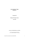
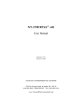
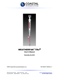
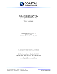
C-5 SAM™/N
WEATHER COMMAND
SHIPBOARD SYSTEM
USER’S MANUAL
Rev. November 02, 2006
P/N: 0302115003
COASTAL ENVIRONMENTAL SYSTEMS, INC.
820 1st Avenue South, Seattle, WA 98134
Telephone: (206) 682-6048 / (800) 488-8291 Fax: (206) 682-5658
www.CoastalEnvironmental.com
C-5 SAM/N User Manual
Shipboard System
TABLE OF CONTENTS
1.0
SETUP.................................................................................................................... 3
2.0
SHIPBOARD C-5 SAM/N DATA SPECIFICATIONS .................................... 4
2.1
OUTPUT DATA SPECIFICATION .................................................................. 4
2.1.1
Format: Serial ASCII code ........................................................................ 4
2.1.2
Message: Conform to NMEA 0183 ver 2.00 ............................................. 4
2.1.3
Definition: $WI Talker Identifier – Weather Instruments ......................... 4
2.1.3.1
Transducer Measurements ...................................................................... 4
2.1.3.2
Wind Speed and Angle ........................................................................... 4
2.1.4
Check Sum Value:..................................................................................... 5
3.0
INSTALLATION.................................................................................................. 6
3.1
SELECTING AN INSTALLATION SITE ........................................................ 6
3.2
INSTALLING THE SENSOR HEAD................................................................ 7
3.3
INSTALLING THE DISPLAY .......................................................................... 8
4.0
MAINTENANCE.................................................................................................. 9
4.1
SCHEDULED SERVICE ................................................................................... 9
4.2
C-5 SAM/N MAINTENANCE........................................................................... 9
4.3
WIND SENSOR MAINTENANCE ................................................................... 9
4.4
TEMPERATURE / RH SENSOR MAINTENANCE ...................................... 10
4.5
BAROMETER MAINTENANCE.................................................................... 10
4.6
CABLES AND CONNECTOR MAINTENANCE.......................................... 10
4.7
DISPLAY UNIT MAINTENANCE................................................................. 10
5.0
UNSCHEDULED MAINTENANCE ................................................................ 11
5.1
INSTALLATIONS PROBLEMS ..................................................................... 11
5.2
DISPLAY / NMEA OUTPUT FAILURE ........................................................ 11
5.3
SENSOR FAILURE ......................................................................................... 12
5.3.1
Wind ......................................................................................................... 12
5.3.2
Temperature / Relative Humidity ......................................................... 14
5.3.3
Barometer ................................................................................................ 14
6.0
SHIPBOARD WEATHER................................................................................. 16
6.1
A LITTLE MARINE METEOROLOGY......................................................... 18
6.2
SHIP INDUCED ERRORS .............................................................................. 19
6.2.1
Wind Errors ............................................................................................ 19
6.2.2
Temperature Errors ............................................................................... 20
6.2.3
Humidity Errors...................................................................................... 22
6.2.4
Barometer Errors.................................................................................... 23
6.3
CONTAMINATION BY SALT ....................................................................... 24
6.4
DATA AVERAGING METHODS .................................................................. 25
7.0 SCHEMATICS.......................................................................................................... 26
Coastal Environmental Systems (206) 682-6048
ii
C-5 SAM/N User Manual
Shipboard System
IMPORTANT NOTE
The nose cone of the wind monitor is removed (unscrewed) for
protection against damage during shipment. Put the nose cone back on
by screwing it to the wind monitor body.
Since the nose cone has fine threads, make sure when you put the nose
cone back onto the wind monitor body that it is not cross threaded.
Coastal Environmental Systems (206) 682-6048
iii
C-5 SAM/N User Manual
Shipboard System
C-5 SAM/N shown with optional Repeater (upper left)
C-5 SAM/N showing all interconnections:
top: side view of C-5 SAM/N display box (shown in top photo at
bottom left), top-left: C-5 SAM/N power supply, bottom and bottomleft: optional Repeater and Repeater power supply.
Coastal Environmental Systems (206) 682-6048
1
C-5 SAM/N User Manual
Coastal Environmental Systems (206) 682-6048
Shipboard System
2
C-5 SAM/N User Manual
Shipboard System
COMMUNICATION GUIDE
Shipboard C-5 SAM/N for Real-Time Systems
1.0
SETUP
The C-5 SAM/N is a meteorological instrument, which samples
continuously and outputs data at a set rate. The user can choose output
formats and set the data output rate using a terminal connected to the C-5
SAM/N. This section describes the communication with the C-5 SAM/N.
Set the terminal program in your computer as follows:
Baud rate:
Start bits:
Stop bits:
Data bits:
Parity
4800
1
1
8
none
Connect a test cable from the C-5 SAM/N to the serial port on your
computer. The C-5 SAM/N will commence operation as soon as power is
applied to the power connections on the test cable.
INPUT POWER SPECIFICATION:
Voltage:
Current:
12 ± 1.5 VDC
0.9 Amp max (with radio)
When power is applied the C-5 SAM/N will respond with a line of data like
the one below.
$--XDR, C, 26.0, C,, H, 44, P,, P, 1.0218, B, *1924,
$--MWV, 4.2, R, 71, N, A*3314,
Coastal Environmental Systems (206) 682-6048
3
C-5 SAM/N User Manual
Shipboard System
2.0
SHIPBOARD C-5 SAM/N DATA SPECIFICATIONS
2.1
OUTPUT DATA SPECIFICATION
2.1.1 Format:
Serial ASCII code
4800 baud
8 data bits
1 stop bit
no parity
2.1.2 Message:
Conform to NMEA 0183 ver 2.00
$WIXDR, C, x, C,, H, x, P,, P, x, B, *hh
$WIMWV, x, R, x, N, A*hh
2.1.3 Definition: $WI Talker Identifier – Weather Instruments
XDR Transducer Measurements
MWV Wind Speed and Angle
*
Precedes check sum value
hh
Check sum value
2.1.3.1
Transducer Measurements
Field 1
Field 2
Field 3
Field 4
Field 5
Field 6
Field 7
Field 8
Field 9
Field 10
Field 11
Field 12
Transducer 1 type, C, Air Temperature
Transducer 1 Data
Transducer 1 Units of Measure, C, degrees
centigrade
Transducer 1 ID, null field
Transducer 2 type, H, Relative Humidity
Transducer 2 Data
Transducer 2 Units of Measure, P, Percent
Transducer2 ID, null field
Transducer 3 type, P, Barometric Pressure
Transducer 3 Data
Transducer 3 Units of Measure, B, Bars
Transducer 3 ID, null field
The characters following the “*” are a check sum.
2.1.3.2
Wind Speed and Angle
Field 1
Field 3
Wind Angle (vane direction) in degrees
Reference, R, Relative to vessel
Coastal Environmental Systems (206) 682-6048
4
C-5 SAM/N User Manual
Field 4
Field 5
Shipboard System
Wind Speed
Wind Speed Units, N, in knots
The characters following the “*” are a check sum.
2.1.4 Check Sum Value:
The checksum value is calculated by XOR’ing (exclusive OR’ing, also
known as Modulo 2 Sum) the 8 binary data bits (not stop or start bits) of
each valid data character in the sentence, between the “$” (HEX 24) and the
“*” (HEX 2A).
The delimiter “*” (HEX 2A) indicates that the face value of the following
pair of ASCII characters represents the hexadecimal value of the upper and
lower nibbles (4 bit values), respectively, of the checksum binary byte.
The values of “$” (HEX 24), “*” (HEX 2A) and the alphanumeric value of
the checksum following the “*” (HEX 2A) are not included in the checksum
calculation.
Coastal Environmental Systems (206) 682-6048
5
C-5 SAM/N User Manual
3.0
Shipboard System
INSTALLATION
The C-5 SAM/N is a sensitive instrument. It is rugged and reliable, but you
must use care in placing it on the ship. Readings can be corrupted because
of poor placement.
3.1
SELECTING AN INSTALLATION SITE
1.
Read Section 6.0 about shipboard weather.
Location on the ship affects measurement
accuracy. Choose an exposed and
uncontaminated site.
2.
Stay forward of the stacks.
Stay forward or above stack emissions. Diesel
spray and exhaust particles will contaminate
the sensors and dirty the C-5 SAM/N.
3.
Avoid high vibration.
The C-5 SAM/N is rugged, but continuous high
vibration or other violent motion will reduce
the lifetime of any instrument.
4.
Locate as high as possible.
The best location is as far forward and as
high as possible.
5.
Avoid high RF fields.
Ships are great sources of radio frequency
interference (RFI). Avoid the radar beam or
other high fields.
6.
Accessibility.
The C-5 SAM/N will need routine maintenance
so make sure it is located in an easily
accessible place.
Coastal Environmental Systems (206) 682-6048
6
C-5 SAM/N User Manual
3.2
Shipboard System
INSTALLING THE SENSOR HEAD
____Choose the best location.
____Align the sensor head mounting post. The mounting post aligns
towards the bow of the ship and parallel with the ships axis. A proper
alignment is necessary for accurate wind direction measurements.
____Affix the mounting post to the ship. The post can be welded or
clamped to the ship. The post must not rotate during use since this will
affect the wind direction measurement. Be sure the alignment stays
accurate while fastening the mount. The mount must be painted or
otherwise protected any place that the paint has been removed by the
mounting process.
____Locate a junction box for the cable connection within 1 meter of the top
of the sensor head mounting post. This box will provide a place for the
connection of the one-meter cable from the sensor head to the cable,
which will be run through the ship to the display unit.
____Place the wind monitor propeller on the wind monitor and hand tighten
the nylon nut to hold it on. The writing on the edge of the propeller
blades should face into the wind.
____Place the sensor head on the mounting post and tighten the mounting
screws in place. Use Never-Seize or equivalent grease on the threads of
the screws to allow removal of the sensor head when maintenance is
necessary. The sensor head will align to the bow of the ship when it is
installed on the mounting pipe.
____Run the 1 meter cable from the sensor head into the junction box and
temporarily seal the box and cable if the connecting cable is not yet
ready to be spliced. Otherwise, splice the cable together and seal the
box and cables.
Coastal Environmental Systems (206) 682-6048
7
C-5 SAM/N User Manual
3.3
Shipboard System
INSTALLING THE DISPLAY
____Determine where the display will be located on the bridge.
____The display mounts with four bolts through the box flange. Drill holes
for the display and mount the display to the bulkhead.
____Determine the cable routing for the sensor head cable, the power cable
and the NMEA 0183 data output cable. If the terminal strips are
located on the wrong side of the box for easy cable routing, the box can
be rotated so that the barometer port is up, and the display faceplate can
be removed and rotated to be upright.
Coastal Environmental Systems (206) 682-6048
8
C-5 SAM/N User Manual
Shipboard System
4.0
MAINTENANCE
4.1
SCHEDULED SERVICE
Scheduled service is best performed in port in mild and clear weather and
with two people.
LINE ITEM
C-5 SAM/N
SERVICE PERIOD
(months)
6
Wind Monitor
6
Temperature
Rel. Humidity
24
3 or less if dirty
Barometer
6
Cables
6
4.2
SERVICE DESCRIPTION
Check condition of case and base
mount. Clean up.
Check bearings for salt
contamination or wear. Replace
wind monitor if necessary.
Check accuracy with deck sensor.
Change the filter. Check accuracy
using a sling psychrometer on the
deck, if necessary.
Check barometer against deck
standard. Set offset if necessary.
Inspect all cables for cuts, wear, or
corrosion, Check MS connectors.
C-5 SAM/N MAINTENANCE
The C-5 SAM/N is a sealed weather tight assembly with no moving parts.
The only maintenance required is to clean it and be sure all nuts and bolts
are tight.
____ Clean the case of oil and stack deposit.
____ Check for minimal corrosion.
____ Check to be certain that the sensor head mount is firm with no
wobble or vibration.
4.3
WIND SENSOR MAINTENANCE
____ Check bearings for resistance or wear. Replace sensor if
necessary.
____ Verify speed and direction accuracy.
Coastal Environmental Systems (206) 682-6048
9
C-5 SAM/N User Manual
4.4
Shipboard System
TEMPERATURE / RH SENSOR MAINTENANCE
_____ Replace the filter.
____ Verify sensor accuracy.
4.5
BAROMETER MAINTENANCE
____ Verify sensor accuracy.
____ Set offset if necessary.
4.6
CABLES AND CONNECTOR MAINTENANCE
____ Check connectors in the junction box. They should be free of
any corrosion. Replace if necessary.
____ Check condition of waterproof tape and sealants. Replace if
necessary.
____ Check cables for damage or wear.
4.7
DISPLAY UNIT MAINTENANCE
____ Brightness good.
____ Check all electrical connections. They must be clean and
corrosion free
____ Check the barometer port to be sure there is no dirt or
obstruction in the tube.
Coastal Environmental Systems (206) 682-6048
10
C-5 SAM/N User Manual
5.0
UNSCHEDULED MAINTENANCE
5.1
INSTALLATIONS PROBLEMS
Shipboard System
System installed - nothing works!
Problem: The system has just been installed but nothing happens.
Most installation problems are the result of wiring errors and cable
problems. Carefully check the wiring against the schematic to be sure
no mistakes were made.
There are two major parts to the C-5 SAM/N system: the sensor head
and the display. Both parts must be operating for the system to work.
5.2
1.
Check the power to system.
Check the power to the system. The C-5 SAM/N uses the 12
VDC power at the display box.
2.
Check power to display.
If there is power to the display, it will light. Depending upon
your display, you may see sensor data with asterisks instead of
numerical output. If it doesn’t show anything, it may be
defective.
3.
Check the display to sensor head cable carefully for damage
or misconnection. The C-5 SAM/N may function erratically or
with very incorrect data values if only one or two of the wires
damaged or mis-wired.
DISPLAY / NMEA OUTPUT FAILURE
This section assumes that the system has been installed properly and the
cables are wired correctly.
If anyone has just made changes to the C-5 SAM/N or the system, check
those changes to be sure that they aren’t causing the new problem. If any
parameters are changed in the C-5 SAM/N (whether intentionally or not),
they could affect the operation of the system.
Coastal Environmental Systems (206) 682-6048
11
C-5 SAM/N User Manual
Shipboard System
Display is dark.
Problem: The display is dark – no visible characters or back light.
Check the A/C power to the A/C to D/C power supply. If it is okay,
check the D/C power out of the power supply. Check to be sure
power is on the terminal strip. If there is power on the terminal strip
and the display does not light, have the display serviced.
Display lights, but no headings or numbers.
Problem: The display lights, but either (a) no headings appear, or (b) there
are headings but no numbers - only asterisks (***).
If the display lights, it has power. Check the data light on the
faceplate of the display. It should be off and flicker as data is updated
every 10 or 11 seconds. If there is no flicker or there are bad data
values, check the display to sensor head cable. If the cable is okay,
have the display box and the sensor head serviced.
Display works, but no data transfer.
Problem: The display works but the Integrated Bridge System (IBS) is not
getting data from the C-5 SAM/N.
If the display works, the sensor head is working. Check for cable
problems on the NMEA Tx lines to the IBS. If the Tx lines are okay,
look for a problem in the IBS or the data format and baud rate. If no
problem is found, have the display box checked.
5.3
SENSOR FAILURE
This section assumes that the C-5 SAM/N and the display are
functioning but some data value(s) appear to be in error.
5.3.1 Wind
Wind speed is extremely low.
Coastal Environmental Systems (206) 682-6048
12
C-5 SAM/N User Manual
Shipboard System
Problem: Wind speed is zero or extremely low.
Visually check to see that the wind propeller is turning. The propeller
could be broken or the bearings may be worn. Worn bearings would
produce a zero or low wind value.
If the propeller is turning, yet the wind speed is zero, a problem in the
sensor wiring is likely. Replace the wind sensor. If this fails to solve
the problem, the problem is most likely inside the sensor head or
cables (assuming that other sensors are operating correctly).
Wind direction zero, wrong or doesn’t change.
Problem: Wind direction is zero, wrong or doesn’t change with the wind.
Check the wind speed value. If there is not wind speed measurement,
there will be no wind direction value (it will read zero).
Visually check to see that the wind vane is not broken or obstructed.
If the vane is freely moving, the propeller is turning and there is a zero
for the direction – and you’re sure that the winds is not from dead
ahead – a broken wire in the wind sensor is indicated. Replace the
sensor. As above, if this doesn’t solve the problem, the problem could
be inside the C-5 SAM/N.
If the direction is wrong but the alignment pin is correct, call in a
problem report. The C-5 SAM/N may have to be returned to the
factory for repairs.
The vane must rotate freely to track the wind. The vane is supported
by bearings, which can wear or accumulate deposits preventing free
rotation. Worn wind sensors can be repaired or replaced.
Wind direction is always off by the same amount.
Problem: The wind direction is always off by the same amount.
The wind direction is reported as apparent wind. This is relative to
the ships heading. When the sensor head mount was installed the
guide pin had to be aligned to the bow. Check the alignment of the
sensor head mount. If it is off, realign it.
Coastal Environmental Systems (206) 682-6048
13
C-5 SAM/N User Manual
Shipboard System
5.3.2 Temperature / Relative Humidity
Temperature / Relative Humidity read extremes or never changes.
Problem: Temperature and/or humidity sensor reads extreme low or high
value, or never changes.
A temperature or humidity value that is extremely low or high, or
never changes readings, indicates a shorted or an open wire in the
sensor or the C-5 SAM/N. Replace the sensor. If the problem
persists, have the C-5 SAM/N tested.
Temperature / Relative Humidity reads high or low, but changes.
Problem: Temperature and/or humidity sensor reads high or low, but does
change with the weather.
A sensor can drift slightly over a period of time. If the drift is more
than 1.0 deg C or 5% RH the sensor should be replaced. Be sure that
the problem is not caused by the ship heating or cooling the sensor, or
causing changes in the humidity.
The humidity sensor is affected by salt or engine exhaust build-up
more that the temperature sensor. Replace the filter on the sensor, or,
if the sensor has no filter, gently clean any deposits from the sensing
elements and install a filter. The sensor elements are extremely
fragile, and care must be taken when cleaning them.
5.3.3 Barometer
Barometer reads high or low constant value.
Problem: The barometer reads high or low by a nearly constant value.
The barometer must be corrected for the altitude above sea level of the
C-5 SAM/N. This is a parameter which can be set in the C-5 SAM/N
menu. If the barometer has been adjusted correctly, there may be a
problem in the sensor or the sensor calibration values. Return the C-5
SAM/N for service.
Coastal Environmental Systems (206) 682-6048
14
C-5 SAM/N User Manual
Shipboard System
Barometer is sometimes off.
Problem: The barometer is sometimes wrong, but not always.
The barometer can be affected by the wind blowing past the sensor. If
the barometer value changes rapidly by large amounts, it could be
defective; but check the reading when the wind is low.
Barometer is way off.
Problem: The barometer is off by a large error.
If the barometer reads a negative number, it is either not installed or it
has failed. If it has failed, replace it.
If the barometer never changes value, or is giving a very incorrect
value, then it may be out of calibration. The sensor should be
replaced and tested and/or re-calibrated.
Coastal Environmental Systems (206) 682-6048
15
C-5 SAM/N User Manual
6.0
Shipboard System
SHIPBOARD WEATHER
Do I trust the bridge or the C-5 SAM/N?
You’re an experienced seaman with years at sea, and you know marine
weather. You’ve used a bridge barometer, and you know how to reduce
apparent winds to true winds (or you’ve seen it done). You are probably
aware of the fact that ships have been taking measurements the same way
since the Second World War.
Suddenly, there’s a new computerized weather gadget called a C-5 SAM/N
with readout on the bridge, right next to your old dials. Instant suspicion!
What is this intruder, this C-5 SAM/N? Is it any good? Let’s see how it
compares to my standard equipment.
Aha! My bridge temperature says 5° but C-5 SAM/N says 2.5°. And look at
this, my barometer (the one I’ve trusted for the past 15 years!) shows a flat
1000 millibars and C-5 SAM/N reads 996, a four millibar error! And finally
the relative winds are way off, I’m reading 34 knots and C-5 SAM/N reads
40.
So who do I believe? The instruments I’ve been looking at my entire
career or this upstart?
Believe ‘em both.
The answer is that probably both readings are pretty nearly correct, and the
errors you are seeing are caused by the ship and the wind around the ship.
This section will explain how measurements of temperature, barometric
pressure, winds, and humidity can vary all over a ship. They vary naturally
on the open ocean anyway, then when the air flows around a ship they vary
even more drastically.
Of course it’s possible that one of the sensors can be bad, and this must be
recognized. But familiarity, followed by understanding, is the crucial first
step in the recognition process. Anyone who has been at sea has heard
remarks such as “Oh, our wind direction is off by about 30 degrees; you can
tell by the flag on the bow. I always add 30 degrees to my apparent
direction.” That seaman is familiar with their equipment; (s)he has been
watching it for months.
Coastal Environmental Systems (206) 682-6048
16
C-5 SAM/N User Manual
Shipboard System
Familiarity takes time.
The C-5 SAM/N represents an entirely new method of measuring
meteorological quantities; it is the most significant advancement in weather
observation at sea in the past 50 years. The numbers you read maybe
different than your old equipment, but they are better measurements. The
goal of taking measurements is to measure the air as if the ship was not
there; as if the sensors were floating in space and not in any way affecting
the air flow.
This section explains the following:
A.
How marine meteorological quantities vary naturally;
B.
How the ship affects the air; and
C.
How placement of the C-5 SAM/N is essential to getting
consistently good weather measurements (see also the
installation section).
We will try to explain what you can expect from the sensors you have and
how best to install the C-5 SAM/N on your ship.
Finally, we will talk briefly about the most crucial maintenance issues,
which affect measurement accuracy. Often a little routine maintenance will
provide surprising improvements.
Coastal Environmental Systems (206) 682-6048
17
C-5 SAM/N User Manual
6.1
Shipboard System
A LITTLE MARINE METEOROLOGY
The Surface Layer
Air blows over the ocean with a little gustiness. Even with large waves, to
the air the ocean is as smooth as an ice covered lake. However, there is
some friction and the wind near the surface is slowed down. In fact, the air
right at the ocean is stuck to the surface and moves at the same speed as the
ocean current at the surface.
The air drags the water at the surface – this is what disperses oil spills. The
water surface current is approximately 2-3% of the wind speed at 10 m
height. For example, if the winds were 30 knots, an oil slick would move at
about 0.3 knots (that’s 7.2 miles per day) just from the winds.
Typically, the wind speed would change from 0.3 knots right at the surface
to 30 knots at 10 m above the surface, and it could be as high as 45 knots at
40 meters above the surface. The exact relationship is complicated and
scientists are still trying to understand it.
“So,” you ask, “where do I measure winds, and who is right?”
Wind speed, wind direction, temperature, and humidity all change in the
vertical in a similar fashion – considerable change in the bottom 1-2 m and
less change above that. From the ocean surface to a height of about 50 m is
called the “surface layer”. However, above about 5 m height the change is
very gradual except in very unusual conditions, such as very calm winds
over cold water. So the guidelines from the World Meteorological
Organization say that all ships measurements, except the barometer, do not
need to be corrected for height before they are reported. The barometer
correction is a simple added amount that depends on the height of the
barometer above sea level (1 mbar per 8 meters of height).
As we will see next, this applies for measurement made in free air, which is
untroubled by the ship. The ship itself can cause significant variation in the
measurements.
Coastal Environmental Systems (206) 682-6048
18
C-5 SAM/N User Manual
6.2
Shipboard System
SHIP INDUCED ERRORS
6.2.1 Wind Errors
Into this untroubled air comes a ship, steaming at 5-30 knots. An observer
on the ship feels the air coming from some direction. This wind is called the
“apparent wind” because it is the wind relative to the observer on the ship.
Usually the apparent wind is coming over the bow.
Seamen know about the winds on a ship at sea. To windward the wind
strength is felt. To leeward the wind speed drops and turbulence (gustiness)
is felt as the wind breaks over the ship superstructure.
The figure below shows a typical case of winds blowing around a ship. The
lines with arrows are “streamlines”. Lines closer together indicate higher
wind speeds and curly lines indicate turbulence. The numbers are of wind
speed measurements if you had a sensor at that location.
Ahead of the ship, before the wind “feels” the ship, the normal wind-ocean
layer causes the speed to decrease from 20 to 30 m height to zero (nearly) at
the surface.
As the wind blows over the ship the streamlines get closer together meaning
the winds speed up. Scientists call this “streamline compression” and the
resulting increase in speed can be considerable. The errors certainly depend
on the direction of the wind relative to the ship.
Coastal Environmental Systems (206) 682-6048
19
C-5 SAM/N User Manual
Shipboard System
6.2.2 Temperature Errors
Temperature is both the simplest and the most difficult measurement to
make properly. The temperature sensor is a simple thermistor (temperature
dependent resistor) that is rugged and reliable. But there are so many
different heat sources occurring naturally that one is never sure of their
accuracy without taking the greatest of care. A few of the sources of error
are given below.
♦ Ocean heating or cooling.
If the ocean is much hotter or colder than the air, then a temperature
surface layer, much like the wind surface layer, exists. Thus, from the
surface to about 5 m height, one can see considerable variation.
♦ Sun Heating.
The sun will heat up the sensor. We have a good shade screen over the
temperature sensor, but even with that the sensor could heat by several
degrees in a hot sun and with light winds.
♦ Ship Heating.
The ship is generally hotter than the air or the water. Thus, as the air
flows over the ship it will warm somewhat. Also the heat radiation from
the ship will warm the sensor.
Coastal Environmental Systems (206) 682-6048
20
C-5 SAM/N User Manual
Shipboard System
♦ Wind Turbulence.
As the wind flows around the ship it will move the air to different levels
thus causing differences.
♦ Stack Gas.
Stack gas is hot and moist – aside from being dirty – and can cause
significant errors in temperature and humidity.
♦ Water on the sensor.
If the sensor is wet, or if there are large pools of water around the sensor,
then in the wind, evaporative cooling can alter the temperature.
Coastal Environmental Systems (206) 682-6048
21
C-5 SAM/N User Manual
Shipboard System
6.2.3 Humidity Errors
Humidity (that is relative humidity) is the % saturation of the air; the amount
of water it contains divided by the total it can hold without condensing. At
the surface of the water the %RH = 100%. Higher up it will decrease to
some steady value.
As the air moves around the ship it carries the same water content it had
before it encountered the ship. The RH % will increase all over the ship
because the air is lifted in its trajectory. The vertical distribution of % RH
depends on the original vertical distribution and the wind pattern over the
ship. In the figure below there can be a 10% RH difference between the
bridge and the mast.
Coastal Environmental Systems (206) 682-6048
22
C-5 SAM/N User Manual
Shipboard System
6.2.4 Barometer Errors
The barometer readings can be affected by wind generating a dynamic
pressure that adds or subtracts from the true atmospheric pressure (also
called the “static pressure”). The exact amount of pressure error depends
upon the wind speed; at high winds the error can be extreme. Wind tunnel
tests show the barometer error inside a closed room with a single opening
depending upon the location of the opening. The error is different if the
opening is on the windward rather than the leeward side. Also, the error is
different on a well-exposed pressure port mounted high on a mast – we
expect the C-5 SAM/N to have this sort of error.
The error in all cases increases by the square of the wind speed (meaning
that if the wind speed doubles, the error increases by four times).
The figure below is a typical case of wind caused dynamic pressure error
around a ship. First, notice that the pressure decreases with height above,
from (in this example) 1000 mbar at the surface to 994 mbar at a height of
30 meters. Therefore, with no wind errors the pressure at the top of the mast
can be three mbar lower than the bridge reading. With a 20 knot wind
blowing, the errors can increase to 6 mbar. Note also that opening or closing
the wing doors on the bridge will cause the bridge barometer to change
several millibars!
Coastal Environmental Systems (206) 682-6048
23
C-5 SAM/N User Manual
6.3
Shipboard System
CONTAMINATION BY SALT
The marine environment is a salty environment. As the waves foam and
break, droplets of water with salt are thrown into the air. These droplets can
be very small and the wind turbulence can carry them to great heights.
Obviously, when the winds are higher, the salt is carried to greater heights.
At heights of 20 m and above, the air is relatively clear and the effects of salt
are minimal. Below this height, salt buildup is a problem and regular
maintenance should be done.
One of the primary advantages of the C-5 SAM/N is that all the sensors
are in the same package at a high position on the ship. Thus,
contamination is minimal and problems are few. Any inconvenience
experienced by having the sensors at altitude is more than made up for by
the increased reliability and reduced maintenance requirements.
Nonetheless, we should be aware of the problems caused by salt, and here
are a few:
♦ Wind Monitor bearings.
Over time the wind monitor bearings will collect salt and ultimately fail.
When you spin the propeller or turn the vane of a new sensor, the
bearings are smooth and have very low friction. After some time they
will feel gritty from the salt. This generally not a problem, as long as the
bearings turn reasonably easy, they will be giving good readings. The
major effect of salt buildup will be to increase the “stall speed” of the
wind monitor, the lowest wind that will still turn the propeller or turn the
vane.
♦ Temperature sensor.
Salt has little, if any, effect on the temperature measurement. The sensor
is sealed and impervious even to immersion in salt water.
♦ Humidity sensor.
Salt deposit will ruin the humidity sensor measurement, but not the
sensor itself. Salt is “hygroscopic”, meaning it absorbs water. So a
deposit of salt will cause the sensor to read a high humidity all the time.
Coastal Environmental Systems (206) 682-6048
24
C-5 SAM/N User Manual
Shipboard System
We provide a protective filter for the RH sensor to keep out both salt
spray and stack gas deposits. The filter should be replaced regularly.
♦ Barometer.
The barometer is a simple strain gauge device with a sealed silicon
pressure chamber. The chamber is exposed directly to the air through a
coil of tubing that is designed to prevent rain from settling into the
chamber. Salt will cause some corrosion in the chamber, but the lifetime
of the sensor is several years.
6.4
DATA AVERAGING METHODS
The measurements by the sensors are averaged in the C-5 SAM/N. Below is
a brief description of the data processing that is done to produce the numbers
you see on the display.
Wind speed and direction. The winds are vector averaged during the
sampling period (VS,VD). This means that for the averaging duration
(typically 10 seconds) the wind speed and direction are sampled once per
second. Each speed and direction pair are converted to a fore-aft wind and a
cross wind, and these are averaged. At the end, the averaged winds are
converted back to mean speed and direction.
Air Temperature. The air temperature sensor is part of the temperature /
RH sensor. The temperature is sampled each second and an average
temperature (TA) is computed.
Barometric Pressure. The barometer sensor is read several times each
second during the averaging period and an average pressure (BP) is
computed.
Relative Humidity. The relative humidity sensor is read each second and
the average of % RH (RH) is computed.
Coastal Environmental Systems (206) 682-6048
25
C-5 SAM/N User Manual
Shipboard System
7.0 SCHEMATICS
Coastal Environmental Systems (206) 682-6048
26
C-5 SAM/N User Manual
Coastal Environmental Systems (206) 682-6048
Shipboard System
27