1
US007504576B2
(12) United States Patent
Georges
(54)
METHOD FOR AUTOMATICALLY
(58)
Inventor:
(73)
Assignee: MediLab solutions LLC’ Chicago’ IL
715/850, 851
See application ?le for complete search history.
Alain Georges, Saint Paul (FR)
Notice:
(
56
)
R f
C't d
e erences l 6
US. PATENT DOCUMENTS
4,399,731 A
8/1983 Aoki ........................ .. 84/103
(Us)
4,577,067 A
3/1986 Levy et al. .
11/1988
10/1991
Filed:
Subject to any disclaimer, the/term Ofthis
patent is extended or adjusted under 35
5,099,740 A
3/1992 Minamitaka .... ..
U_S_C_ 154(1)) by 0 days_
5,177,618 A
1/1993 Dunlap et a1. ............. .. 358/335
C
_
_
OTHER PUBLICATIONS
_
Beatnik Rick Music Format, 2 pages, 2002.
_
_
_
Aug. 4, 2003, noW Pat. NO. 7,176,372, which is a
continuation of application No. 09/691,314, ?led on
Oct. 17, 2000, noW abandoned, Which is a continua
Prlmary Exammerileffréy Done/1S
_
_
(74) A110""6% Agent) 0" FlrmiLoudermllk & Assoclates
tion-in-part of application No. 09/690,911, ?led on
Qct- _17> 2000: HOW _aba_ndoneds which is a Continua‘
(57)
ABSTRACT
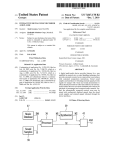
A method of automatically processing a melody is disclosed.
tlon'ln'part of aPPhCaUOn NO- 09/691302, ?led on
Oct- 17, 2000,110‘” Pat- NO- 6>392>133-
A computing resource is provided for generating or process
ing a series of MIDI events as part of an automatic music
_
_
_
_
algorithm. A memory area contains a plurality of sound
Forelgn Apphcatlon Pnonty Data
Oct. 19, 1999
Nov. 17, 1999
(FR)
(FR)
(51) Int, C],
G10H 7/00
(52)
(Continued)
Continuation of application No. 10/ 634,346, ?led on
_
(30)
d
(Continued)
Oct. 4, 2007
Related US. Application Data
_
t'
84/649
FOREIGN PATENT DOCUMENTS
484047
10/1991
EP
Prior Publication Data
US 2007/0227338 A1
_
Masaki ................... .. 369/32
Lisle etal. . . . . .
. . . .. 84/645
( on “we )
Feb. 10, 2007
(65)
(63)
. 379/10101
4,787,073 A
5,054,360 A
(21) Appl. No.: 11/705,555
(22)
84/ 600,
84/603, 625, 645; 434/307 A; 715/727,
EVENTS
(75)
Mar. 17, 2009
Field of Classi?cation Search ................. ..
PROCESSING A MELODY WITH
SYCHRONIZED SOUND SAMPLES AND MIDI
(*)
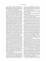
US 7,504,576 B2
(10) Patent N0.:
(45) Date of Patent:
samples, each including an audio stream. One or more of the
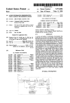
................................. .. 99 13036
................................. .. 99 14420
Sound Sample/51110111965 a Speech Sentence, andthe automatic
music algorithm temporally synchronizes Playback Of a
sound sample to the series of MIDI events in accordance With
a musical laW, and the melody is automatically processed.
(2006.01)
US. Cl. ......................................... .. 84/645; 84/603
13 Claims, 7 Drawing Sheets
397
Music
Database
39
DM
36
Ml S thesizer M2
9
yn
433
MA3
66
Sound
Processor
Samples
9
31
38
43 w
32
_o
FM
Digitized
Musical
Flles
Radio
Recelver
,_\/ 6 4
US 7,504,576 B2
Page 2
Us. PATENT DOCUMENTS
5,267,318 A
5,281,754 A
11/1993
Severson ................... .. 381/51
V1994 Farrett eta1~
5,300,723 A
4/1994
5307456 A
5308915 A
4/1994 MacKay
5/1994 Ohyaetal
5,350,880 A
5369217 A
5386081 A
9/1994 Sato ............... ..
11/1994 Yam?shitaetal
V1995 Nakada er a1
5,425,297 A *
6/1995
9/ 1995 Minamitaka
YoungJr ---- --
5496962 A
3/1996 Meler er a1~
5523525 A
6/1996 Mumkami eta1~
A
12/1996
IiZuka eta1~
6,916,978 B2
84/609
ltO ........... ..
5,451,709 A
5581530
6,835,884 B2
6,897,368 B2
------
6,970,822 B2
12/2004 IWamoto etal. ............. .. 84/609
5/2005 Georges et a1. .
.. 84/609
7/2005
Georges et a1‘ _____________ __ g4/609
11/2005 Fay et a1. .................. .. 704/270
84/601
7,078,609 132*
7/2006
395/154
395/22
7,183,482 B2*
7,189,915 B2*
2/2007 Kobayashi ................. .. 84/645
3/2007 Kobayashi ................. .. 84/645
84/609
~84/611
-- 84/609
7241947 132*
7,319,185 B1
2001/0025561 A1
7/2007 Kobayashi
u 84/645
1/2008 Wieder ...................... .. 84/609
10/2001 Milburn et a1. .............. .. 84/609
84/4831
2001/0047717 A1
12/2001
84/609
2002/0023529 A1
- 84/601
2002/0033090 A1
3/2002
84/602
2002/0046315 A1
4/2002 Miller et a1.
2002/0046899
A1
4/2002
MiZuno et a1.
2002/0065074 A1
5/2002
Cohn et 31‘
- - - - -- 369/93
Georges “
Aoki et a1. .... ..
IWamoto etal. ............. .. 84/609
12/1996 Clynes ........ ..
.. 395/200.02
5,627,335 A
5/1997 Rigopulos etal
.... .. 84/635
2002/0166440 A1
11/2002 Herberger
5,633,985 A
5/1997 Severson ..... ..
395/2.76
2002/0l70415 A1
11/2002 Hruska et 31‘
5,640,590 A
A
A
A
A
6/1997 Luther
2002/0175665 A1
11/2002 O’GradYet 31‘
84/610
. 395/807
369/4
.. 84/609
2003/0013497
2003/0079598
2003/0176206
2003/0l83065
A1
A1
A1
A1
1/2003
5/2003
9/2003
l0/2003
Yamakietal. ............ .. 455/567
Nakayama
Taniguchi et a1. ......... .. 455/567
Leach
Fay ------------- --
-- 84/609
2003/0205125 A1
11/2003
Futamase et a1. ............ .. 84/622
84/635
2004/0039796 A1
2/2004 Watkins
704/270
84/609
2004/0064320 A1
2004/00gg169 A1
4/2004 chrysanthakopoulos et 31‘
5/2004 Smith et a1‘
9/1998 Gershen ................... .. 345/339
2004/0106395 A1
6/2004 Suganuma
5/1998
6/1998 Rigopulos et a1. .
5,787,399 A
5,792,971 A
5,801,694 A
7/1998 Lee ............. ..
8/1998 Tirnis et a1. .
5,824,933 A
10/1998 Gabrlel
2004/0109558 A1
5,832,431 A
11/1998
2004/0231499 A1*
5,839,108 A
11/1998 Daberko eta1~
Severson ------------------ -- 704/258
5,864,868 A
1/1999
5,877,445 A
5,886,274 A
3/1999 Huffordetal
3/1999 Jungleib ..
(301K018 -------------------- -- 707/104
5,900,566 A
5/1999
5,913,258 A *
6/1999 Tamura
5,914,941 A
5,928,330 A
6/1999 Janky ....... ..
7/1999 GoetZ et al. .
Mino .... ..
84/602
.. 84/601
6/2004 Koch
11/2004
Kobayashi ................. .. 84/645
2005/0190199 A1
9/2005 Brown et a1.
2006/0156909 A1*
7/2006
2006/0185504 A1*
8/2006 Kobayashi ................. .. 84/645
. 84/610
Kobayashi ................. .. 84/645
FOREIGN PATENT DOCUMENTS
84/604
370/313
709/231
EP
EP
0702366
0747877
9/1995
6/1996
5,969,716 A
5,981,860 A *
10/1999 Davis et a1 ............... .. 345/328
11/1999 IsoZakiet al. ............... .. 84/603
EP
GB
0857343
2306043
10/1996
4/1997
6,008,446 A
12/1999 Van Buskirk et al.
84/603
1/2000 Rigopulos et a1. ........... .. 84/667
6/2000 Gorbet et al. ............. .. 345/302
JP
W0
W0
06295567
10/1994
WO 88/05200
WO 89/02641
7/1988
3/1989
6,074,215 A
6/2000 Tsurumi
434/307
W0
WO 97/15043
4/1997
6,083,009 A
6,084,168 A
7/2000 Kim et a1. ................. .. 434/307
7/2000 Sitrick ....................... .. 84/477
W0
W0
WO 97/35299
WO 98/33169
9/1997
7/1998
6,093,880 A *
7/2000 Arnalds
84/464R
W0
WO 01/63592
8/2001
6,121,533 A
6,143,971 A
9/2000 Kay .......................... .. 84/616
11/2000 Aoki et al. .................. .. 84/609
W0
W0
WO 01/73748
WO 01/86630
10/2001
11/2001
6,143,973 A
11/2000
.. 84/645
W0
WO0186625
11/2001
6,153,821 A
6,182,126 B1
11/2000 Fay et al. .................... .. 84/634
1/2001 Nathan et al. ............. .. 709/219
W0
W0
WO0186626
W0 0186627
11/2001
11/2001
6,192,340 B1
B1 *
B1
B1*
B1
B1
B1
181/142
. 395/806
5,763,804 A
6,225,547
6,230,140
6,245,984
6,281,424
6,326,538
6,343,055
............ ..
N8 eta1~
Milne et al. .
Hubinger
Tsurumi ..
7/1997
8/1997
10/1997
ll/l997
5,753,843 A
6,011,212 A
6,072,480 A
.. 84/611
2/2002 Kurakake et a1. ........... .. 84/610
5,590,282 A
5,648,628
5,655,144
5,675,557
5,689,081
“ 84/645
2/2001
5/2001
5/2001
6/2001
8/2001
12/2001
1/2002
Kikuchi .... ..
Abecassis .... ..
. 704/270
W0
WO0186628
11/2001
Toyama et al. .............. .. 84/611
Severson .................. .. 704/278
Aoki et al. ..
84/611
Koike et a1. ................. .. 84/636
Kay .......................... .. 84/635
Ema et a1. ....... ..
. 369/531.6
W0
W0
W0 0186629
W0 02/077585
11/2001
10/2002
OTHER PUBLICATIONS
6,353,169 B1
6,353,172 B1
3/2002 JusZkieWicZ etal. ........ .. 84/600
3/2002 Fay et a1. .................... .. 84/609
Beatnik Audio Engine White P4112946 Page/8,2001
BeatnikAudioEngine, 2pages, 2002.
Beatnik mobileBAE version 02.02W, 2 pages, 2002.
6,353,174 B1
6,425,018 B1
3/2002 Schmidt et a1.
84/609
7/2002 Kaganas et a1. .............. .. 710/1
Beatnik mobileBAE version 11.02W, 2 pages, 2002.
Combiningmusical theory andpractice, IBM Computer Music Cen
6,429,863 B1 *
8/2002 LoPiccolo et a1. ......... .. 345/419
ter, apparently Jun. 29, 1995.
6,506,969 B1
V2003 Baron
-- 84/609
Dream,anAtmel Company: SAM9407, “Programmer’s Reference,”
6,541,691 B2
6,576,828 B2
4/2003 Tolonen et a1. .............. .. 84/616
6/2003 Aoki et a1. .................. .. 84/635
pp, 1-61, Rev, 11, Dec, 1996,
Dream, an Atmel Company; SAM9709, “Integrated Sound Studio,”
6/2003 Thorpe et al. ..
pp, 1.20, Jan, 1998,
6,576,878 B2
. 219/645
6,639,141 B2
10/2003 Kay .......................... .. 84/609
Genjam; An Interactive Genetic Algorithm Jazz rmproviser, John A,
6,657,116 Bl
12/2003 Gunnerson ................. .. 84/615
Biles, popular Version ()fpaper 4pMU1 apparently presented Dec,4,
6,683,241 B2
1/2004 Wieder ...................... .. 84/609
6,696,631 B2
6,815,600 B2
2/2004 Smith et a1. ................. .. 84/645
11/2004 Georges et a1. ............. .. 84/609
1997.
GenJam: A Genetic Algorithm for Generating JaZZ Solos, John A.
Biles, date apparently after 1993.
US 7,504,576 B2
Page 3
GenJam Populi: Training an IGA via Audience-Mediated Perfor
Mobile Media Analyst, “Music Services Might Soon Break Out of
mance, John A. Biles, apparently Sep. 15, 1995.
the Ring-Tone Mold,” Mobile Media management report, pp. 5-12,
Information on how to purchase Kid Riffs, IBM, date unknown.
Interactive GenJam: Intergrating Real-Time Performance with a
Motorola C350 Cellular Phone User Manual, selected pages on
Genetic Algorithm, John A. Biles, apparently after 1996.
Hemmings, Richard, Scary Computer Music, apparently from Avant
Magazine, Issue 7, Summer 1998, p. 12.
Kid Riffs, IBM Computer Music Center, date unknown.
Louis, Duke, Milesiand MAC? Business Week Archives, appar
ently Dec. 18, 1995.
Mithic, a New Generation of Music, Thomson Multimedia, 3 pages,
Jul. 8, 2002.
Mithic, the First Interactive Music Composer, 2 pages, 2002.
Thomson Multimedia presents Mithic Technology, 3 pages (2 slides
per page), undated.
Thomson Multimedia launches Mithic, a unique Technology to to
deliver personalized interactive Music, Feb. 25, 2002.
Thomson to present the Mithic Composer Technology at
DEMOmobile Conference, Sep. 19, 2002.
Jan. 10, 2003.
MotoMiXer Sound Editor, Motorola, Inc., pp. 1, 2, 129-131, 2002.
Music Sketcher, IBM Computer Music Center, date unknown.
Music Sketcher Section Details, IBM, apparently 1998.
Musical Computers, Miles Davis, version 2.1, apparently from The
Economist, Dec. 6, 1997, p. 92.
Roland Corporation, “Personal Music Assistant Owner’s Manual”,
Dec. 18, 1995, Entire Manual.
Yamaha Mobile Audio 3, MA-3, YMU762, Yamaha LSI, Yamaha
Corp., Preliminary May 9, 2001, p. 1-14.
Tom Hays, “DirectMusic For The Masses”, Gamasutra.com article
believed to be originally published in Game Developer Magazine
Sep. 1998, 27 pages.
Microsoft, “Microsoft DirectMusic Producer: Game Development
Tutorial”, believed to be dated Nov. 12, 2002 (?le date of electronic
?le) or earlier, 52 pages.
* cited by examiner
US. Patent
Mar. 17, 2009
Sheet 1 of7
US 7,504,576 B2
18
17
FIG. 1
US. Patent
Mar. 17, 2009
Sheet 2 on
US 7,504,576 B2
294
292
291
HQ'F
Music
Musical
ADPCM &
Compression
Parametric
Sound FX
D?coder
Algorithms
F1
USB PC
/I Interface
Synthesizer
28
/CODEC
Digital
Structure
31¢ I t
Multi-media
with MIDI
geraglve
Platform
rap rcs
Interface
e
26
/
\
TV/Video
Flash
FM
Interface
Memory
927
919
f
291
\
Keyboard
LCD
Interface
P°wer
Digital
Receiver
Eggs
Tuner
823
933
932
FIG. 2
US. Patent
397
Music
Database
Mar. 17, 2009
DM
36
Sheet 3 of7
Ml
9
39
.
US 7,504,576 B2
' Syntheslzer
M2
,
41
e
\
Processor
32
MA3
‘
—@
Sound
Samples
51
38
39
396
1»
rocessor
429A
M1 Synthesizer M2 > DAC
MAZ
S2
' DAC
42B
FIG. 4
8A2
44
$140
US. Patent
396
Processor
396
Processor
Mar. 17, 2009
Sheet 4 of7
3
9
M1’ Synthesizer M2
S2
US 7,504,576 B2
487
I
MA3
DAC —0
39
M1 Synthesizer
M2
M3
FIG. 6
497
MA3
DAC —0
US. Patent
Mar. 17, 2009
396
M1
Processor
S2
Sheet s on
3:
,
I
M
Syntheslzer
US 7,504,576 B2
487
MA3
' DAC —0
FIG. 7
Instrumental Sounds -
q/ 48
Sound Samples
36
INST
9
47
v r39
Processor
s2
-
Syntheslzer
9
M3
M1“
DAC —0
FIG. 8
49
52
51
SIM
FIG. 9
g
SIAZ
36
3s
Q
9
DAC S12 Processor S13 Memory
7
US. Patent
Mar. 17, 2009
Processor 0%
Sheet 7 of7
US 7,504,576 B2
Mliilggllogles @43
Al A2
K37
K39
Music
-
D atab aS e
58
I L 9 _S@]
S3
2
Synthesizer
‘
A3
—§3
43A
Sound
38/11 Samples
Memory
397
Music
D at ab ase
DM
36
FIG. 11
M1
a
39
.
' Synthesizer
M2
43B
(\
MA3
{K 66
Processor
Sound
Samples
e
32
_O
‘
31
FM
Digitized
_
Radlo
Receiver
[V6 4
38 43% Musical
Files
FIG. 12
US 7,504,576 B2
1
2
METHOD FOR AUTOMATICALLY
PROCESSING A MELODY WITH
SYCHRONIZED SOUND SAMPLES AND MIDI
EVENTS
player a module that generates music or other sounds Which
either can be mixed With the originally recorded sound (sound
mixing), or can replace the originally recorded sound (sound
dubbing). This sound mixing or dubbing can be performed
either at video/audio record time or at play time.
This application is a continuation of US. application Ser.
No. 10/634,346 ?ledAug. 4, 2003, now US. Pat. No. 7,176,
372, Which is a continuation of US. application Ser. No.
Additionally the invention envisions selection of musical
pieces either out of a library stored for instance in the form of
digitiZed musical ?les, MIDI ?les or other types of ?les, or
from pieces that are composed in a pseudo-random fashion
09/691,314, Oct. 17, 2000 noW abandoned Which is a con
tinuation-in-part of US. application Ser. No. 09/690,911 ?led
Oct. 17, 2000 (Which claims priority on French Patent Reg.
No. 99 13036, ?led Oct. 19, 1999) and Ser. No. 09/691,302
using, for example, a synthesizer function to play original
musical pieces.
The invention further envisions selection of musical pieces
according to a speci?ed musical style, in a pseudo-random
fashion, or according to prede?ned criteria, Wherein the audio
?led Oct. 17, 2000 now US. Pat. No. 6,392,133 (Which
claims priority on French Patent Reg. No. 99 14420, ?led
Nov. 17, 1999).
?les meet the prede?ned criteria and are either extracted from
a music library or are generated by an automatic composition
BACKGROUND OF THE INVENTION
(a) Field of the Invention
The current invention relates to a device that provides for
interaction With a user during recording, playing, composing
and modifying musical selections.
(b) Description of Related Art
Various devices capable of composing a musical piece
automatically have been developed, such as that described in
20
station by the use of one or several of the aforementioned
functions. Further, the invention permits selection of musical
pieces, by a user, either from a library in Which musical pieces
are stored as compressed musical ?les, MIDI ?les or other
25
US. Pat. No. 4,399,731. These devices are based on synthe
siZers of instrumental sounds on Which are applied, for
instance as per the MIDI (Musical Instrument Digital Inter
random fashion using a synthesizer function to play original
musical pieces.
30
can possess one or several audio inputs, Which permit mixing
or replacement of the sound track that Was recorded originally
during the recording of the image With an external audio
similar types of ?les, from pieces recorded from the output of
a radio receiver, or from pieces that are composed in a pseudo
face) standard, “scores” of notes that are composed automati
cally. Various devices capable of recording or playing video
recordings have already been developed, such as digital or
analog camcorders and other video recorders. These devices
function. The resulting sounds are used either during the
video recording or during the video playback.
The present invention represents an improvement of the
aforementioned devices by simulating the reception of a radio
Thus, the present invention provides for selection accord
ing to a pre-selected musical style, in a pseudo-random fash
ion or according to a pre-de?ned criteria, of audio ?les to be
played from a speaker, Wherein the audio ?les meet the pre
de?ned criteria and are either extracted from the library or
generated by an automatic composition function. Further, the
35
source.
recording of or the automatic generation of sentences that
mimic the speech of a “disc-jockey” or of an announcer
Furthermore, there also exist various devices that are
permits combination of speech passages With the musical
pieces being played, thereby giving the user the illusion that
capable of playing recorded pieces, such as digital compact
disc players, players of compressed ?les (for instance as per
the MPEG-level 3 standard), etc. Finally, there exist devices
incorporating a tuner, Which permit reception of radio broad
he is listening to an actual radio station.
40
BRIEF DESCRIPTION OF THE DRAWINGS
casts via electromagnetic Waves.
SUMMARY OF THE INVENTION
45
An interactive digital multi-media device provides a user
With multiple related features, Wherein it is not necessary that
the user have training in musical or sound handling arts. A
programmable memory is used to store digital audio and
voice samples. External sound recovers provide external
sound signals, such as radio and TV signals that may also be
stored. Playback means is provided connected to the stored
audio and voice samples and the external sound signals.Auto
erence to the attached draWings in Which:
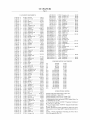
FIG. 1 is a perspective of the digital multi-media device of
50
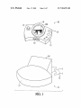
FIG. 3 is a block diagram of the automatic composer of the
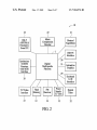
FIG. 4 is a block diagram shoWing one structure for sum
ming outputs in the present invention.
55
FIG. 6 is a block diagram shoWing a ?rst variant of the
diagram of FIG. 3.
60
FIG. 7 is a block diagram shoWing a second variant of the
diagram of FIG. 3.
samples are mixed With a melody in the process of the auto
The invention herein further represents an improvement
over prior art devices by integrating in a video recorder or
FIG. 5 is a block diagram shoWing another structure for
summing outputs in the present invention.
previously recorded sound samples Wherein the sound
matic composition. The sound samples Will typically, but not
exclusively, be human voice samples.
the present invention.
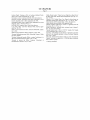
FIG. 2 is a functional block diagram of the present inven
tion.
present invention.
matic musical composition instructions are stored so that the
user is able to create unique musical compositions. Compo
nents are provided that function to mix externally obtained
sound With the unique musical compositions and stored audio
and voice samples to provide altered audio and voice presen
tations.
The present invention includes an improved automatic
composition device that adds to instrumental sounds some
The above objects and other advantages of the present
invention Will become more apparent by describing in detail
the preferred embodiments of the present invention With ref
65
FIG. 8 is a block diagram of another embodiment of the
automatic composer of the present invention.
FIG. 9 is a block diagram of a variation of the present
invention.
FIG. 10 is a block diagram of another aspect of the present
invention.
US 7,504,576 B2
4
3
sion ratio for equivalent sound quality as compared to previ
ous compression techniques, i.e., MP3. DMA compression
techniques alloW a compression ratio approximately tWice
FIG. 11 is a block diagram of an additional aspect of the
present invention.
FIG. 12 is a block diagram of yet another aspect of the
present invention.
that of MP3, thereby alloWing for over tWo hours of music to
be stored on a 64 megabyte SmartMedia card. The WMA
DETAILED DESCRIPTION OF THE PREFERRED
EMBODIMENTS
playback function supports the Digital Rights Management
(DRM) technology that is used With audio ?les. This technol
ogy can be used to encrypt the compressed data, Which can
The present invention Will be described in greater detail
With reference to certain preferred and alternative embodi
ments. As described below, re?nements and substitutions of
the various embodiments are possible based on the principles
then only be decoded correctly With a private key. As a result,
a user can doWnload music from the Internet that is protected
With the DRM technology and receive rights to play music on
a particular DMM that has been previously registered. ASP
and teachings herein.
and MIDI ?les can be copied on the SmartMedia card either
via a serial PC connection offered by the DMM device or
directly With an off the shelf SmartMedia card reader. Internal
The invention disclosed herein is an interactive digital
music player that alloWs one or more users to listen to, com
pose, and interact With music in any environment. The device
is a hand-held digital music player that offers numerous
unique features that, until noW, have not existed in a single
music product. One of the many features, the Electronic DJ
(e-DJ) automatically composes and plays in real-time music
20
memory and SmartMedia memory 19 further provides the
ability for the DMM to obtain ?rmware and sound upgrades
from the Internet.
An electronic DJ and virtual radio functions are provided
in a multitude of genres (such as a dance or techno), Which can
by a group of musical algorithms 21 that alloW a user to
be mixed With user-supplied voice samples. The e-DJ offers a
unique interactive Way of playing With music. At any
moment, the user can take the control of the music played by
the e-DJ via an attractive interface (joystick, graphical dis
play). The user can change the music patterns played by
automatically create and play many different types of music
such as dance, techno, rap, easy listening, etc. Unlimited
hours of random music may be generated by the musical
25
a user is able to tune to a favorite radio station or to a virtual
various instruments, change the relative level, apply effects,
play pre-recorded samples, etc.
radio station. While music is playing a user is able to take
control over automatic composition being undertaken by the
Further, the disclosed device alloWs the user to listen to,
create, doWnload, store, and interact With music, and includes
algorithms. The device also operates as a musical composer
assistant. An FM receiver 23 is provided in the DMM so that
30
musical algorithms 21 and to add the users oWn touches. The
an FM radio receiver. Users can listen to both compressed
user may interact With the music being played by Way of
audio and MIDI karaoke music ?les, store music on a plug-in
changing the tempo and pitch. Consequently, interaction is
SmartMedia memory card (SSFDC storage device), and carry
the unit to any location for playing. The device is capable of
available in as much as the user is able to play voice, music or
sound samples that can be recorded With a built in micro
phone or obtained from the FM radio receiver or any other
source. The samples are obtained through the use of a high
storing more than 1000 MIDI karaoke-?le songs on a 64 MB
smart media memory card and it can provide over 120 min
35
utes of digital music play time. In addition, the disclosed
quality audio compression circuit 24 and are stored in the
device is able to create music ?les, accept music ?les created
by the user, doWnload music from the Internet via a PC, take
a music transferred from a PC, or, accept music added from
of the DMM (FIG. 1) provide for introducing the sound
SmartMedia memory section 19. The controls 13 on the face
40
effects such as Wobbler, dobbler, etc. and can be applied at a
any other smart media memory card. When connected to a
user’s Will during playback of the recorded samples. Addi
docking station, the device offers additional features like
tionally the controls alloW the user to take even more control
insertion of Karaoke lyrics in a video source for display on a
TV screen, MIDI PC connection or remote control.
instrument or a group of instruments in a fashion normally
over the musical content by selecting relative volume of an
number of cables 12 are shoWn for connection to a number of
only possible through the use of a mixing table. The sound of
a particular instrument may be altered using ?lters and also
ports (not shoWn) situated at the rear of the docking station 11.
may be saved to be later played over again and even to be
The device 10 as shoWn has a group of controls 13, including
buttons, knobs, jacks, etc. and a display 14 on its front surface.
A connector Within a slot 16 is shoWn on the device that is
keys While the graphical display of 14 provides visual feed
FIG. 1 shoWs the device 10 and its docking station 11. A
45
edited later. Controls 13 are intuitive using traditional player
50
surface of a base 17 on the docking station 11. The docking
station includes an inclined surface 18 that supports the
oWn designs.
Audio compression circuit 24 preferably is a circuit based
device in the docking station When connection is made
betWeen the connector in slot 16 and the connector in the
55
docking station.
60
data from a SmartMedia memory card 19. The digital audio
source is either compressed or MIDI. The DMM offers a user
the capability to interact With a song being played by chang
ing pitch and tempo. The audio compression techniques sup
ported in the DMM is Microsoft WindoWs Media Audio
(WMA), illustrated at 22 in FIG. 2, having ?les in the active
streaming format (ASF). WMA provides a higher compres
on a speech compression algorithm using, for example, adap
tive differential pulse coded modulation (ADPCM) that can
be applied to a useful portion of the recording. As is knoWn in
the art, techniques such as PCM and ADPCM provide meth
ods of compression of analog data that has been sampled and
The device 10 is shoWn in the block diagram of FIG. 2 and
Will be referred to as a Digital Multi Media Platform (DMM)
hereinafter. A large number of features are included in the
DMM, one of Which is the ability to playback digital audio
back in real time of the action the user is undertaking With the
musical content. As a result users With no special musical
education or skill are able to alter and compose music to their
con?gured to mate With a connector (not shoWn) on a rear
65
digitiZed, typically in Which the samples have been digitiZed,
and difference betWeen samples are stored/ sent (rather than
the samples themselves), or With adaptive techniques a pre
dicted sample/sample difference is computed, and What is
stored/transmitted is the difference betWeen the predicted
value and the actual value, etc. Such compression techniques
are knoWn in the art and used, for example, in various tele
phony-type systems.
US 7,504,576 B2
6
5
usually represented in analog form and take large amounts of
memory, comparatively, when digitized.
Further, digital notes are easily altered while digital sounds
A built in microphone (not shown) in the DMM is used for
Karaoke and DJ functions. Further, it is used with a music
synthesizer 26 to provide for audio mixing and other audio
sound effects. The synthesizer 26 provides a MIDI interface
are not readily changed. As a result, the instant invention may
use a microprocessor operating at about 25 MHz and needs
whereby, due to the small size of a MIDI ?le, a large number
of songs may be made to ?t in the ?ash memory 19 containing
the SmartMedia cards. The SmartMedia Flash memory pro
only about two (2) megabytes of storage, although, of course,
the particular clock speed and storage size are exemplary
vides for storage of compressed digital/audio MIDI/Karaoke
?les and voice samples. This is currently the most compact
embodiments and the invention is not limited thereto. This
may be seen to be much less processor speed and memory
Flash Memory form available. The digital nature of the MIDI
?les allows tempo and pitch of music to be dynamically
than used in the least capable desktop computer, for example.
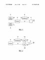
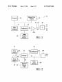
According to the functional diagram of FIG. 3, one typical
adapted to the users requirements. Moreover, when a singer’ s
voice is taken from the built in microphone within the DMM
and mixed with synthesized or stored sound samples, lyrics
embodiment of the automatic composition device of the
present invention includes essentially a processor 36, a
memory 37 containing a music database for use in the auto
may be displayed on a TV/video interface 27 or on the display
14 of FIG. 1 . An external microphone may be plugged into the
matic composition device, a memory 38 for storing sound
samples utilized by the automatic composition device, a
music synthesizer 39, and a summation and digital to analog
DMM for even more ?exible usage.
When the DMM is connected to the docking station 11 and
playing MIDI or Karaoke songs, a digital light show is avail
able through the TV/video interface 27. The resulting colorful
conversion circuit 41 interconnected as shown. Processor 36
is able to compose automatically a melody out of the database
20
patterns have movements and shapes following the beat of
speci?c instruments or serve as a compliment to lyrics dis
played on the screen 14 or just as a visual assist to the elec
tronic DJ music.
A universal serial connection 28 to a personal computer
allows transfer of audio ?les to and from the SmartMedia/
?ash memory 19. Additionally the serial connection is avail
able to perform a ?rmware upgrade. The MIDI interface 26 in
in memory 38, in such a way that processor 1 delivers in
synchronism on its output a control signal M1 connected to
25
30
be upgraded readily by a user by downloading through the
MIDI PC interface 28. A digital instrument tuner for all
modern and classical instruments is shown in FIG. 2 at 32.
The compact design obtained in the DMM to afford the
portable nature of the device is obtained by housing some
functions required only when using the product in a nonmo
bile environment to be placed in the docking station 11 of
FIG. 1. These functions include the circuitry required for the
insertion of Karaoke lyrics in a video source and for display
35
ROM or EPROM memory can store the microprocessor pro
40
gram and the music database in memory 37 used by the
automatic composition device. However, a greater ?exibility
will be granted by non-volatile memories: RAM memory
saved by a disposable or rechargeable battery, or Flash
EEPROM memory (electrically erasable). The non-volatile
45
memory can be used at the very least to store the sound
samples in memory 38, so that they are saved when the
invention is powered off. It can also be used to store the music
database in memory 37 for use by the automatic composition
device, as well as a microprocessor operating program. This
or regular batteries. Multiple functions are provided through
50
electronic DJ, voice and sound samples and radio. Playback
and record keys are available on the face of the DMM together
with general volume control keys. Power, video and audio
connectors, and microphone input connectors are provided on
the docking station 11. Additionally, the docking station has a
memories. Clock speed and memory capacity may be rela
tively low, 25 MHz and 2 MB being ample in the preferred
embodiments. A RAM memory (volatile memory) can serve
as the working memory of the microprocessor and can be
used to store the sound samples in memory 38, whereas a
embodiment as shown at 33 in FIG. 2. The DMM is con?g
ured to include two AA batteries. These may be rechargeable
controls 13 on the DMM such as compressed audio playback,
which forms the output of the invention, can then be presented
in audio form by a stereo sound system.
In a preferred embodiment of the invention, the processor
is made of a microprocessor or microcontroller having a
synchronizing clock and being linked to one or several
on a TV screen as well as an external microphone connection
for Karaoke recording. A MIDI in/out interface is provided in
the docking station 11 for connection to a personal computer
or to another MIDI device. A power jack and charge control
(not shown) is provided at the rear of the docking station to
provide the DMM with a 3 .3 volt power supply in a preferred
synthesizer 39 and a sound sample signal S2. An output signal
M2 of the synthesizer and sound sample signal S2 are then
summed and converted to analog form in circuit 41 to deliver
the complete audio signal MA3. This audio signal MA3,
the DMM 10 converts to a synthesizer when connected to a
MIDI sequencer through the USB PC interface 28. Firmware
for the DMM is stored in the Flash Memory and can therefore
stored in memory 37 using an automatic composition algo
rithm containing composition instructions. The automatic
composition algorithm also utilizes the sound samples stored
55
permits easy update of the music database and the micropro
cessor operating program by means of downloading updates.
The summing of output signal M2 of the synthesizer and of
sound sample signal S2 is obtained using various methods
and circuitry described as follows.
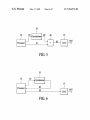
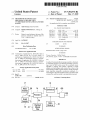
In a ?rst scheme for performing the summing of M2 and S2
standard MIDI interface with in and out connectors. This
interface is useable for communication with a personal com
(FIG. 4), output signal M2 of synthesizer 39, which is a digital
puter for audio ?le transfer or ?rmware upgrade.
The invention disclosed herein is useable by persons hav
ing no appreciable musical expertise. It presents a new way of
listening to music wherein a user may modify existing music,
compose new music, and save and play back music. Music
patterns composed by the user or taken from favorite com
analog converter 42. Sound sample signal S2 generated by
signal, is converted to an audio signal MA2 by digital to
processor 36, which is also a digital signal, is separately
60
posers may be retained in a music database or library. The
composition device of the present invention utilizes a combi
nation of notes rather than sounds. Notes, being represented
digitally, require less memory for storage than sounds that are
65
converted to an audio signal SA2 by a second digital to analog
converter 43. Then audio signals MA2 and SA2 are summed
by analog adder 44 to deliver an audio output signal MA3.
The analog adder 44 can consist of an operational ampli?er
mounted in an adder con?guration.
In a second manner of performing the summing of M2 and
S2 (FIG. 5), output signal M2 of synthesizer 39 and sound
sample signals S2 generated by processor 36 are added by
US 7,504,576 B2
7
8
digital adder 46 to form a combined digital signal M3. This
digital signal is then converted to an audio signal MA3 by a
digital to analog converter 47. While this manner of perform
S1A1 to digital sample signals S12. The sample signals are
ing the summing requires only one digital to analog converter
read by processor 36 and stored either in its memory 38, or, in
the case of the embodiment of FIGS. 7 and 8, in the memory
contained Within the synthesizer 39. The memory may be
47, it nevertheless requires a digital adder 46.
RAM or ?ash as indicated previously.
Various processes may optionally be used to reduce the
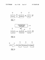
In a variant of the second manner of performing the sum
memory requirements to store the samples. The folloWing
examples are not limiting:
(a) once the recording is over, the silent periods Which
precede and folloW the useful portion of the recording can be
ming of M2 and S2 (FIG. 6), output M2 of synthesizer 39 is
sent back to processor 36, Which then performs by itself the
summing of digital signals M2 and S2 (in this variant, signal
S2 only exists in a virtual form in the processor). Thus, the
processor delivers directly on output M3 the compound digi
tal signal, Which is converted to an audio signal MA3 by
digital to analog converter 47. This variant requires only one
digital to analog converter and does not require a speci?c
digital adder circuit, but conversely it requires an additional
input on the processor to read the output of the synthesizer.
eliminated automatically;
(b) a speech compression algorithm such as Adaptive Dif
ferential Pulse Coded Modulation (ADPCM) 24 can then be
applied to the useful portion of the recording.
In the process of automatic composition of music, the
processor can treat the sound sample signals as a special case
of a musical instrument. Thus, the association of sound
In a second variant of the second manner of performing the
summing of M2 and S2 (FIG. 7), Which is applicable to the
sample signals With the notes sent by the instruments is an
integral part of the automatic composition process. The pro
case Where synthesizer 39 itself comprises a processor (mi
croprocessor and/or digital signal processor), the summing of
digital signals M2 and S2 canbe performed by the synthesizer
20
HoWever, the processing of sound samples has certain fea
modi?ed for this purpose. Indeed, either the synthesizer has
an additional input to read signal S2 as shoWn in FIG. 7, or
signals M1 and S2 are multiplexed on a single input of the
synthesizer (variant not shoWn on a ?gure). In the latter case,
cessor then extracts information from the available pool of
sound samples in the same Way as from the music database.
tures. First of all, the invention is not restricted to using sound
25
if a MIDI standard protocol is used, the multiplexing of sig
nals M1 and S2 Will be made much easier by putting the
information relevant to sound sample signals S2 in “System
samples that have been pre-recorded for a given type of
instrument, but also envisions using sound samples that have
been recorded freely by the user. In addition to some special
delivers directly on output M3 the compound digital signal,
effects that Will be described later, the processing of sound
samples consists of selecting a sample in the pool of available
samples according to a pseudo-random sequence, then select
ing the moment to start playing the sample, taking into
account the melody that the processor is simultaneously com
posing, in such a Way that the sample starts at the beginning of
Which is converted to an audio signal MA3 by digital to
a musical bar, or in speci?c cases at another moment that is
Exclusive” MIDI messages. Thus, the synthesizer performs
internally the summing of signals M2 and S2 (in this variant,
30
signal M2 only exists in a virtual form in the synthesizer) and
analog converter 47. This second variant also requires only
one digital to analog converter and does not require a speci?c
35
digital adder circuit, but conversely, compared With a stan
dard synthesizer circuit, it requires a modi?cation of the
synthesizer to read and add sound sample signals S2.
In another preferred embodiment of the invention, appli
cable to the case Where synthesizer 39 itself comprises a
governed by certain musical laWs (Which may depend on the
music style). The sound sample can then be played either in its
entirety or in part, and it can be repeated or not repeated.
40
Furthermore, the sound samples may be modi?ed to
include various special effects depending on the style of
music created by the automatic composition device. To quote
only a feW of such special effects: echo addition, vibrato,
distortion, frequency modulation, various ?ltering processes
processor, memory 38 for storing sound samples is linked to
synthesizer 39 instead of processor 3 6. Given that synthesizer
to shape the sound spectrum, etc.
39 already possesses a memory that contains instrumental
sounds that are used as basic units for music synthesis, a
variant of this embodiment consists in storing the tWo types of
One aspect of the current invention relates to a system such
as described above that also may include, orbe included in, an
automatic soundtrack generator that operates to merge an
45
sounds, i.e., the basic instrumental sounds and the sound
independent sound track With a video sequence during
recording or playback of the sequence (aspects of the other
samples, in a sounds memory 48 as shoWn in FIG. 8. In this
embodiment, the summing of digital signals M2 and S2 is
naturally performed by the synthesizer, according to the same
process as described for the variant of FIG. 7. Thus, the
embodiments described herein could be used to record or
50
program executed by the processor of the synthesizer 39 is
modi?ed to permit these neW operations (storing sound
samples and summing them With instrumental sounds). The
program modi?cations performed by the processor of the
synthesizer can be minimized by organizing the program in
module 56 connected to store the signal V1 on storage unit 58
such as a tape or a digital memory. The storage unit is con
55
such a Way that the synthesizer processes sound samples as a
special case of basic instrumental sounds; for example, as by
assigning a MIDI channel to the sound samples or as an
alternative by de?ning the sound samples as special notes of
a percussion type instrument.
playback desired audio tracks in conjunction With video that
being recorded and/or played back, etc.). FIG. 10 represents a
system in block diagram form shoWing an external video
input 53 providing a signal V1 to a video and sound recording
60
nected to a video and sound playback module 61 that pro
duces an output V2 connected to a video output module 62
and an audio output A2 connected to a sound generation
module 57. Items 56, 58, 61 and 62 are generally contained in
a commonly knoWn camcorder device. The camcorder device
also includes an external sound input element 54, such as a
In a preferred embodiment of the invention, the invention
microphone, producing an audio output Al. Output Al is also
alloWs a user to record sound samples With a microphone via
commands that permit the user to start and stop a recording.
connected to sound generation module 57. A control module
59, shoWn connected to items 56, 58, 61 and 57 in FIG. 10,
An internal microphone and/or an external microphone input
is required. As seen in FIG. 9, a microphone 49 provides an
output S1A1 connected to the input of preampli?er 51. An
analog to digital converter 52 converts the microphone signal
65
selects sounds generated by sound generation module 57 to
produce output S2 providing audio output 63.
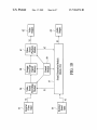
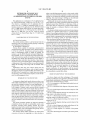
According to the functional diagram of FIG. 11, the inven
tion can typically be embodied by a module that generates
US 7,504,576 B2
10
music or other sounds and Which comprises essentially pro
cessor 36, memory 37 containing the music database of the
select, according to certain criteria, musical ?les out of the
library of musical ?les or is able to compose automatically,
according to the automatic composition algorithm, a melody
automatic composition device, musical synthesizer 39,
memory 38 storing the sound samples for the musical syn
out of the database stored in memory 37. The automatic
thesiZer, a digital to analog conversion circuit 43, a summa
tion circuit 58 and a memory 42, internal or external to the
composition algorithm also utiliZes the sound samples stored
in memory 38, Which may include some speech sentences, in
invention, containing a library of digitiZed musical ?les. The
such a Way that processor 36 delivers in synchronism on its
memory elements 37, 38 and 42 can be made of one or several
conversion in converter 43, delivers an analog signal A3
outputs a control signal M1 connected to synthesiZer 39 and
a sound sample control signal S2. Output signal M2 of the
synthesiZer and sound sample control signal S2 are then
summed and converted to analog form in circuit 43 that pro
vides the complete audio signal MA3 for connection to a
speaker or speakers (not shoWn). In a similar Way, the output
of radio receiver 64 can be mixed upstream, as a digital signal,
Which can optionally be mixed With the recorded audio A2 or
or doWnstream, as an analog signal, of circuit 43 to add a
With the external audio input Al in summation circuit 58 to
supplementary sound source to the complete audio signal
MA3. The audio signal MA3 forms the output of the inven
tion that can then be played by the aforementioned speakers in
distinct physical components. Processor 36 is able to select,
according to certain criteria that are pre-de?ned or de?ned by
a user, musical ?les out of the library in memory 42, or is able
to compose automatically a melody out of the database stored
in memory 37, With an automatic composition algorithm. The
output signal S3 of the synthesiZer, after digital to analog
deliver the mixed complete audio signal S1/S2. This mixed
audio signal S1/ S2, Which forms the output of the invention,
can then be used as a sound source at video/audio record time 20 a stereo system.
In a preferred embodiment of the invention, the processor
(real time) (S1) or at play back time (time shifted) (S2). As a
result prerecording of movie soundtracks, for example, is
is made of a microprocessor or microcontroller linked to one
unnecessary. A simple Way is provided for a user to change
sound content, pitch, etc. for implementation in a video
soundtrack.
In a preferred embodiment of the invention, the processor
or several memories. A RAM memory (volatile memory) can
serve as the Working memory of the microprocessor and can
be used to store the sound samples 38, Whereas a ROM or
EPROM memory can store the microprocessor program and
25
the music database 37 used by the automatic composition
36 is made of a microprocessor or microcontroller linked to
one or several memories. A RAM memory (volatile memory)
can serve as the Working memory of the microprocessor,
Whereas a ROM or EPROM memory can store the micropro
algorithm. HoWever, a greater ?exibility Will be granted by
30
cessor program and the music database 37 of the automatic
composition device. However, a greater ?exibility Will be
granted by non-volatile memories: RAM memory saved by a
disposable or rechargeable battery, or Flash EEPROM
memory (electrically erasable). The non-volatile memory can
be used to store the music database in memory 37 for use by
35
be used to store the music database 37 of the automatic
digital form of predetermined instruments.
the automatic composition algorithm, the digitiZed musical
?les of the library 42, as Well as a microprocessor operating
program. This permits easy update of the music database and
the microprocessor operating program by means of doWn
composition device and the digitiZed musical ?les of the
library in sound samples memory 38, as Well as the micro
processor program. This permits easy update for the music
database and the microprocessor program.
The synthesiZer 39 and the microprocessor 36 of FIG. 11
cooperate to select banks of sound samples according to
predetermined processor instructions to provide the synthe
siZer output S3. The sound sample banks contain sounds in
non-volatile memories: RAM memory saved by a disposable
or rechargeable battery, or Flash EEPROM memory (electri
cally erasable). The non-volatile memory can be used at the
very least to store the sound samples in memory 38, so that
they are saved When the invention is poWered off. It can also
loading updates.
40
Processor 36 can also be used to select the sound source or
sources, including radio receiver 64 or one of the sources in
memories 37, 38 and 42 described above. It can also be used
to select one of a number of preset radio stations, including
either actual radio stations or illusory radio stations. Illusory
45
The processor 36 can also be used to select the sound
stations in reality play sound samples and musical pieces that
have been stored in digital form or that are composed auto
matically as described herein. Moreover, a sound input
device, such as a microphone 66, is useful to input voice
signals, encoded in memory, to be used in construction of
source or sources described above. Furthermore, the proces
sor can be used to select commands Which permit activation
functions such as playing a recording, selecting and mixing
an audio source, or controlling any other functions that are 50 illusory radio station sound patterns.
The controls 13 to Which reference Was made in FIG. 1
combines the functions of blocks 57 and 59 of FIG. 10.
include a joystick and a number of direct access keys to
commonly found in video recorder based equipment. This
According to another feature of the present invention, a
device is provided that simulates a radio station including a
player of musical pieces, either recorded and digitiZed or
synthesiZed. According to the functional diagram of FIG. 12,
a typical embodiment of the invention comprises essentially a
processor 36, a memory 37 containing a music database for
use by an automatic composition algorithm, a memory 38
storing the sound samples, a musical synthesiZer 39, a sum
simplify entry into various interactive modes by users of the
DMM device of the present invention. Certain operating
55
60
sequences for speci?c interactive modes Will noW be
described.
To enter Electronic-DJ, press the [e-DJ] direct access key.
The LCD Will display “E-DJ-” in the status line and a selec
tion of music styles is proposed: Techno, Dance, Hip-Hop,
mation and digital to analog conversion circuit 43, a radio
etc.
receiver 64 and a memory 42, internal or external to the
To select the desired style, use Joystick Up/DoWn
To start playing auto-composed music of the selected style,
press the play/pause key the LCD Will display the music
I-Way screen representing six instrument lanes: Drums, Bass,
Riff, Lead, Samples and Microphone. The screen is animated
invention, containing a library of digitiZed musical ?les,
Wherein these elements are interconnected as shoWn. The
memory elements 37, 38 and 42 can be made of one compo
nent or several physically distinct components. Processor 36
is in communication With the memory elements and is able to
65
With sound Waves or pulses synchronized With music beats.
US 7,504,576 B2
11
12
Referring again to FIG. 1, display 14 preferably displays
To change pitch on the microphone input, press Pitch/
Tempo key together With joystick up or doWn.
To change the microphone volume, press Effects key
together With joystick up or doWn.
music tunnels, lanes, sound Waves, beat pulses, etc. as
described elseWhere herein, such as is generally illustrated by
display feature 14A.
To change music tempo, press Pitch/Tempo key together
To modify the microphone echo, press Effects key together
With joystick left or right.
Press stop to mute microphone.
Press play/pause to un-mute the microphone.
To exit Electronic-DJ mode, choose any other mode by
pressing the appropriate direct access key.
Playback of compressed audio and Karaoke is accessible in
the “Songs” mode. This mode alloWs to play digitally
recorded WMA (MP3) songs, MIDI songs, Karaoke songs
With joystick left to speed up or right to sloW doWn.
To change music pitch, press Pitch/Tempo key together
With joystick left to speed up or right to sloW doWn.
To change music pitch, press Pitch/Tempo key together
With joystick up to higher the pitch or doWn to loWer it.
Press play/pause to pause the music.
Press stop to stop the music and go back to style selection
screen.
Press forWard to start a neW song.
and User songs saved during an e-DJ session.
Press backWard to restart the current song.
To enter Songs mode, press the [Songs] direct access key.
The LCD Will display “e.Songs” in the status line and a list of
Press Save/Edit key to save the current song as a user song
on the SmartMedia card.
available songs or song lists on the SmartMedia card to
To select a speci?c lane, use joystick left/right.
The image on the screen Will shift left or right and present the
I-Way seen from the neW lane.
20
play/pause key. The LCD Will display the play song screen.
To change the relative volume of the current lane, press
Effects key together With the joystick up or doWn.
To change the reverb on the current lane, press Effects key
together With the joystick left or right.
To enter the Underground mode for the current lane and
The name of the song is scrolling in a banner in the center
right part of the LCD While the audio output level is materi
aliZed by a frame around the name Which siZe is changing
25
loop the current sequence, press joystick doWn.
The transition to music tunnel is marked by a screen ani
mation and the under ground mode is entered for the selected
instrument or sound source (sample or microphone). The
U-ground screen shoWs the inside of a tunnel With sound
Waves on both sides and beat pulses coming toWards the user.
To change music tempo, press Pitch/Tempo key together
With joystick left to speed up or right to sloW doWn.
To change music pitch, press Pitch/Tempo key together
sound effect applied.
35
ground mode.
In instrument tunnels (Drums, Bass, Riff and Lead):
Use Joystick right to select a neW music pattern. Use joy
stick left to come back to previous patterns.
Press Joystick up to go back to music I-Way.
To change the cutoff frequency of the ?lter on the current
Press forWard to go to next song.
40
instrument, press Effects key together With joystick up or
To change the resonance of the ?lter on the current instru
45
See “Editing items” beloW.
Pressing forWard key in the song select screen Will create a
neW song list.
50
To exit Songs mode, choose any other mode by pressing the
appropriate direct access key.
Playback of compressed audio and Karaoke is accessible in
the “Songs” mode. This mode alloWs to play digitally
recorded WMA (MPA3) songs, MIDI songs, Karaoke songs
55
and User songs saved during an e-DJ session.
To change the sample volume, press Effects key together
With joystick up or doWn.
To choose a different sample effect, press Effects key
together With joystick left or right.
Press play/pause to play the sample. If sample playback
had been previously disabled (see beloW), the ?rst press on
play/pause Will re-enable it. Following presses Will play the
selected sample.
Pressing stop Will disable the automatic playback of
samples by the e-DJ When returning to I-Way mode.
To enter Songs mode, press the [Songs] direct access key.
The LCD Will display “e.Songs” in the status line and a list of
available songs or song lists on the SmartMedia card to
60
choose from. Song lists are identi?ed by a speci?c icon.
To select the desired song or list, use Joystick Up/DoWn.
To start the playback of selected song or song list, press the
play/pause key. The LCD Will display the play song screen.
In the Microphone Tunnel:
Use Joystick left/right to select the active microphone:
built-in or docking station. If the docking station is not con
nected, no selection is available.
Press Joystick up to go back to music I-Way.
Press backWard to go to previous song.
Pressing the Save/Edit key in the song select screen or
While a song is playing enters the song edit mode. Depending
on the type of the song (user song, MIDI or WMA), different
parameters can be edited.
Pressing the Save/ Edit key in the song select screen While
the current item is a song list enters the song list edit screen.
Press stop to mute the instrument.
Press play/pause to un-mute the instrument.
In the Sample Tunnel:
Use Joystick left/right to select a sample.
Press Joystick up to go back to music I-Way.
With joystick up to higher the pitch or doWn to loWer it.
Press play/pause to pause the music. Press play/pause
again to resume playback.
Press stop to stop the music and go back to song selection
screen.
doWn.
ment, press Effects key together With joystick left or right.
folloWing the audio level. The status line shoWs the elapsed
time.
If the song is a Karaoke song, the Lyrics are displayed at the
bottom of the LCD. Note: if the song is a user song (composed
With the e-DJ), the music I-Way mode is entered instead of the
play song mode.
The shape of the far side of the tunnel is modi?ed With the
The music Will loop as long as the user remains in the Under
choose from. Song lists are identi?ed by a speci?c icon.
To select the desired song or list, use Joystick Up/DoWn.
To start the playback of selected song or song list, press the
The name of the song is scrolling in a banner in the center
right part of the LCD While the audio output level is materi
65
aliZed by a frame around the name Which siZe is changing
folloWing the audio level. The status line shoWs the elapsed
time.
US 7,504,576 B2
14
13
If the song is Karaoke song, the Lyrics are displayed at the
bottom of the LCD. Note: if the song is a user song (composed
With the e-DJ), the music I-Way mode is entered instead of the
If music is playing (songs or radio), the record source is a
mix of the music and the microphone input if not muted.
To enter Virtual radio mode, press the [v-Radio] direct
access key. The LCD Will display “v.Radio” in the status line
play song mode.
To change music tempo, press Pitch/Tempo key together
and a list of available station presets to chose from as Well as
With joystick left to speed up or right to sloW doWn.
t currently tuned frequency. If no preset has been stored, only
To change music pitch, press Pitch/Tempo key together
the currently tuned frequency is displayed.
With joystick up to higher the pitch or doWn to loWer it.
Press play/pause to pause the music. Press play/pause
again to resume playback.
Press stop to stop the music and go back to song selection
To select the desired station, use Joystick Up/DoWn.
To listen to the selected station, press the play/pause key.
The LCD Will display the radio screen. The name of the radio
station (or frequency if it is not a stored preset) is scrolling in
screen.
a banner in the center right part of the LCD. An animation
representing radio Waves is also displayed. The status line
Press forWard to go to next song.
Press backWard to go to previous song.
Pressing the Save/ Edit key in the song select screen or
While a song is playing enters the song edit mode. Depending
on the type of the song (user song, MIDI or WMA), different
parameters can be edited.
Pressing the Save/Edit key in the song select screen While
the current item is a song list enters the song list edit screen.
shoWs the tuned frequency.
Use Joystick left/right to go to previous/next station is in
the preset list.
20
See “Editing items” beloW.
Pressing forWard key in the song select screen Will create a
25
To exit v.Radio mode, choose any other mode by pressing
the appropriate direct access key.
30
To select the desired sample or list, use Joystick Up/DoWn.
To select the desired sound effect, press Effect key together
doWn to loWer it.
35
To modify the microphone echo, press Effects key together
With joystick left/right.
To start the playback of the selected sample, press the
40
right part of the LCD While the audio output level is materi
45
tion screen.
Pressing the Save/Edit key in the sample select screen or
While a sample is playing enters the sample edit mode.
Pressing the Save/Edit key in the sample select screen
While the current item is a sample list enters the sample list
50
a neW sample list.
To exit Sample mode, choose any other mode by pressing
55
Recording samples is a simple operation possible in almost
any operating mode of the dBl.
Press record and keep record button doWn to record a
sample. Release the record button to end the recording.
Recording is stopped automatically if the sample duration
exceeds 30 seconds.
The record source is chosen automatically depending on
the operation mode.
While e-DJ is playing (I-Way or U-ground modes), the
microphone (built-in or docking station).
present invention.
Although the invention has been described in conjunction
With speci?c preferred and other embodiments, it is evident
that many substitutions, alternatives and variations Will be
apparent to those skilled in the art in light of the foregoing
description. Accordingly, the invention is intended to
the spirit and scope of the appended claims. For example, it
should be understood that, in accordance With the various
alternative embodiments described herein, various systems,
Pressing forWard key in the sample select screen Will create
record is inactive.
If no music is playing, the record source is the active
Reference is also made to co-pending US. application Ser.
Nos. 09/691,302 and 09/690,911 ?led on Oct. 17, 2000 for
“Virtual Radio” and “Automatic Soundtrack Generator,” both
of Which are incorporated by reference herein and both of
Which may utiliZed, alternatively, With embodiments of the
embrace all of the alternatives and variations that fall Within
edit screen. See “Editing items” beloW.
the appropriate direct access key.
To change the microphone volume, press Effects key
together With joystick up/doWn.
play/pause key. The LCD Will display the play sample screen.
aliZed by a frame around the name Which siZe is changing
folloWing the audio level. The status line shoWs the current
effect.
Press stop to stop the sample and go back to sample selec
As Long as no Music is Playing and in the v.Radio Mode, the
Microphone Settings are Made as folloWs:
To change the pitch on the microphone input, press Pitch/
Tempo key together With joystick up to increase the pitch or
1con.
The name of the sample is scrolling in a banner in the center
Pressing the Save/Edit key While a station is playing Will
store it in the preset list.
key. The LCD Will display “e.Samples” in the status line and
With joystick left/right.
To change the sample volume, press Effect key together
With joystick up/doWn.
forWard to tune up.
backWard to tune doWn.
screen enters the preset edit mode.
In the “playing samples” mode, the user can record or play
voice, music or sound samples.
To enter Samples mode, press the [Samples] direct access
a list of available samples or sample lists on the SmartMedia
card to choose from. Sample lists are identi?ed by a speci?c
play/pause to mute the radio.
stop to go back to station preset selection screen.
Pressing the Save/Edit key in the station preset selection
neW song list.
To exit Songs mode, choose any other mode by pressing the
appropriate direct access key.
Press
Press
Press
Press
65
and uses and methods based on such systems, may be
obtained. The various re?nements and alternative and addi
tional features also described may be combined to provide
additional advantageous combinations and the like in accor
dance With the present invention. Also as Will be understood
by those skilled in the art based on the foregoing description,
various aspects of the preferred embodiments may be used in
various subcombinations to achieve at least certain of the
bene?ts and attributes described herein, and such subcombi
nations also are Within the scope of the present invention. All
such re?nements, enhancements and further uses of the
present invention are Within the scope of the present inven
tion.
US 7,504,576 B2
15
16
5. The method of claim 4, further comprising providing a
music database stored in digital form, Wherein the computing
What is claimed is:
1. A method of automatically processing a melody com
resource accesses the music database in accordance With the
prising the steps of:
automatic music algorithm.
providing a computing resource for generating or process
ing a series of MIDI events as part of an automatic music
6. The method of claim 5, further comprising providing a
doWnload interface for receiving updates to the music data
base.
7. The method of claim 1, Wherein the sound sample is
processed in response to user input.
8. The method of claim 1 further comprising providing one
algorithm; and
providing a memory area containing a plurality of sound
samples, each comprised of an audio stream;
Wherein one or more of the sound samples comprises a
or more user input resources suitable for user interactivity;
Wherein at least one user input resource can affect a pitch
speech sentence; and Wherein the automatic music algo
rithm temporally synchronizes playback of a sound
changing function.
sample to the series of MIDI events in accordance With
9. The method of claim 1, further comprising providing one
a musical laW, Wherein the melody is automatically pro
cessed.
2. The method of claim 1, Wherein the musical laW is
comprised of starting the playback at a beginning of a musical
bar.
or more user input resources suitable for user interactivity;
Wherein at least one user input resource can affect a tempo
3. The method of claim 1 Wherein the automatic music
changing function.
10. The method of claim 1, further comprising providing a
graphical user interface for interacting With the automatic
20
interface comprises animated sound Waves or animated
rithm.
4. The method of claim 1, further comprising:
providing a microprocessor executing a microprocessor
operating program, Wherein the microprocessor com
prises part of the computing resource; and
providing a doWnload interface for receiving updates to the
microprocessor operating program.
music algorithm, comprised of instrument lanes.
11. The method of claim 10, Wherein the graphical user
algorithm comprises an automatic music composition algo
pulses.
25
12. The method of claim 1, further comprising providing a
digital light shoW through a TV/video interface.
13. The method of claim 12, Wherein the digital light shoW
comprises colorful patterns having movements or shapes fol
loWing a beat of speci?c instruments.
*
*
*
*
*