1
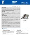
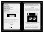
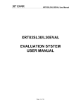
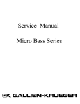
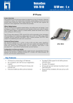
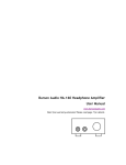
Radio Relay - Vocality to
Vocality
Application Note AN230
Revision v1.5
November 2013
Vocality Application Note
AN230 Radio Relay - Vocality v1.5
AN230 Radio relay - Vocality to Vocality
1
Overview
This Application Note describes how you can set up two Vocality BASICS Hybrid , BASICS Four
Wire or Radio Relay units for Radio Relay applications. In this context Radio Relay is taken to
mean the interconnection of a radio controller with a remote 2-way radio, or the interconnection
of two 2-way radios.
2
Equipment
Vocality units provide two , four or eight audio interfaces with E&M signalling. Each unit is
provided with a WAN , UPNLK or ENET1 Ethernet connector for connection to a distant unit.
Figure 1 Example radio relay using two BASICS four wire units
3
Setup
If you are in Push Config mode, you will need to go to the BASICS Start-up Configuration menu
and place your cursor on the MODE field. Press <Spacebar> to toggle from Push Config to
Normal mode. Press <Esc>, then <Y> to save the changes. The full Main menu is then displayed.
Page 1 of 6
Vocality Application Note
AN230 Radio Relay - Vocality v1.5
You start under the Advanced Config menu at the System Options > System menu to set basic
settings for the node, such as node name.
Figure 2 System Options > System menu for Node 1
The IP > Networks menu will allow you to set IP address/gateway for the four wire/radio relay
ports.
Note: If the units are to be assigned IP addresses in different IP subnets, then you will need to
enter the IP address of the local gateway router in the DEFAULT GATEWAY field.
Figure 3 IP > Networks menu for Node 1
Page 2 of 6
Vocality Application Note
AN230 Radio Relay - Vocality v1.5
The IP > Tunnels > IP Aggregates menu will allow you to configure IP aggregate settings for the
four wire/radio relay ports.
Figure 4 IP > Tunnels > IP Aggregates menu for Node 1
The RATE should be set to an appropriate speed, according to your choice of voice codec and the
number of circuits to be simultaneously active, not forgetting to add an allowance for overheads
such as IP headers and signalling.
Under the Analogue Voice > Analogue Ports menu you can set the 'Destination' for each port as
well as the voice compression algorithm to be applied to each channel.
Figure 5 Setting port destinations for Node 1
You will need to repeat all these steps to set up Node 2, this time with IP address 192.168.0.200
and peer address 192.168.0.199.
Page 3 of 6
Vocality Application Note
AN230 Radio Relay - Vocality v1.5
In the above example Port 1 on one unit is mapped simply to Port 1 on the other, so the
destinations on Node 1 will be 2:0:1, 2:0:2, 2:0:3 and 2:0:4 and the destinations on Node 2 will be
1:0:1, 1:0:2, 1:0:3 and 1:0:4.
4
E&M Signalling and Circuit Activation
E&M is a type of supervisory line signalling that uses DC signals on separate leads, called the 'E'
lead and 'M' lead, traditionally used in the telecommunications industry between telephone
switches.
Four Wire or Radio Relay provides E and M signal leads on the 4-wire interfaces as a means to
allow attached equipment to:
l Signal when a 4-wire circuit should be activated
l Detect when a circuit has been activated by the distant end.
The following diagram shows how the leads are presented. (See Appendix for Pin Assignments
detail.)
Figure 6 E and M signalling
The input ‘M’ circuit has an internal impedance of 15k ohms and is referenced internally to +5V.
It can be stimulated by keying the 'M' lead to any voltage in the range +1.0 to -48V. In practical
terms this means that a PABX chassis ground or -48V reference are both acceptable. It is also
permissible to apply a contact closure between ‘M’ and ‘MREF’ to stimulate the function.
The output signal is provided as a contact closure between the 'E' lead and the 'EREF' lead. The
active state is a 'make'.
5
Radio Relay
You need to set the System menu 'Tie-Line activation' option (under the Advanced Config
menu) to 'M Lead' (default setting), then the 4-wire circuit will be activated and will reserve
bandwidth over the aggregate connection, whenever the 'M' lead is keyed. At the same time,
the 'E' lead on the remote destination port will be activated to signal to the remote equipment
that the circuit has been activated.
These E&M leads can be used to control a remote 2-way radio as shown below.
Page 4 of 6
Vocality Application Note
AN230 Radio Relay - Vocality v1.5
Figure 7 E&M leads used to control a remote 2-way radio
Many radios designed for this type of application will have a suitable 4-wire E&M interface
presented on an RJ45 connector. In this case a straight cable can be used to connect the radio to
the Vocality BASICS Hybrid Audio port or BASICS Four Wire or Radio Relay unit. Similarly the
radio controller will usually present a 4-wire E&M interface for connection to the Vocality
BASICS Hybrid Audio port or BASICS Four Wire or Radio Relay unit.
In earlier software versions TTY commands needed to be issued in order to set damping factors
and simple duplex mode. Refer to the section Radio Relay using TTY commands advanced
settings below.
6
Circuit activation by detection of voice
An alternative to using the E&M leads to activate the channels is to use voice detection.
Automatic voice activation mode may simplify the interconnection requirements between the
Vocality unit and the radio. In this mode the channel is activated and the remote 'E' lead
asserted whenever an audio signal is detected by the BASICS Hybrid or Four Wire or Radio Relay
unit. Two modes are possible:
l Voice detect – 'M' lead: Requires both the 'M' lead to be asserted and presence of audio.
l Voice detect – Auto: Only requires the presence of an audio signal.
The choice of mode is made using the 'Tie-Line Activation' parameter on the System menu.
7
Audio levels
Impedance of Rx and Tx lines: 600ohms nominal
Maximum input level = 6V pk-pk = 2.12Vrms = 8.75dBm
Maximum output level = 7V pk-pk = 2.47Vrms = 10dBm
Conversion Notes:
To convert Peak to RMS voltages: Vrms = 0.3535× Vpp
(
P(dBm) = 10log10 v 2 / (R × p 0 )
To convert RMS Voltage to dBm:
where p 0 is the reference wattage and is 1mW or 1x10⁻³ watts.
)
R is the impedance, in this case 600ohms.
To ensure correct operation of the voice detection function, and to avoid degradation of the
signal/noise ratio, a minimum level of 1V pk-pk is recommended. This corresponds to about 8dBm in a 600 ohm system.
It is therefore not recommended to connect an unamplified microphone directly to the Four
Wire or Radio Relay interface. A microphone can however be connected directly to the Audio
ports for the BASICS Hybrid, so long as the ports are configured to expect a microphone input on
the Analogue Voice > Advanced settings menu. Please note that there is a maximum
Page 5 of 6
Vocality Application Note
AN230 Radio Relay - Vocality v1.5
microphone level input without distortion (with gain setting +28.3dB input), which on the output
is 150mVpk-pk (single ended).
This completes the radio relay setup procedure.
8
Radio Relay using TTY commands advanced settings
The commands below are a starting point for initial setup and testing of radio relay. (To learn
more about TTY commands refer to your User Manual). You may want to adjust these settings to
find the highest quality audio.
l DAMPELEAD
l RXSUPRESS
l RXMUTE
On BASICS Hybrid these parameters are included on the Analogue Voice > Advanced settings
menu.
DAMPELEAD
This feature allows you to filter out transient periods of silence, preventing excessive assertion
and de-assertion of the 'E' lead. When the node is configured to operate in one of the 'Voice
Detect' tie-line modes, this setting allows you to configure the amount of time over which
silence can be continuously detected, before the 'E' lead is de-asserted. A value of 0 will cause
the 'E' lead to be de-asserted immediately on receipt of an indication of silence detection.
The syntax of the command is:
nodename VCHAN 0:1 DAMPELEAD 500
The units used are milliseconds and the default value is 0. If a non zero value is used, any
transition from silent to active again will cause the timer to reset.
RXSUPRESS
When relaying push-to-talk radio signals asserting the 'E' lead causes the radio to begin
transmitting, de-asserting the 'E' lead causes the radio to switch back to receive. With many
radio sets the transition back to receive will produce a burst of noise, which will be sent back to
the distant end and can cause the remote port to transition to transmit, creating a ping-pong
effect where each radio continually switches between Tx and Rx. This setting allows you to
configure the voice port to not pass any received data for a period of time after the de-assertion
of the 'E' lead.
The syntax of the command is:
nodename VCHAN 0:1 RXSUPRESS 1000
The value is in milliseconds.
RXMUTE
This setting suppresses the received voice when the outgoing 'E' lead is activated on the tie-line
port. This effectively makes the port operate in a half duplex mode.
The syntax of the command is:
nodename VCHAN 0:1 RXMUTE ONTX /OFF
9
About Application Notes
Application Notes are intended as a supplement to, rather than a substitute for, your User
Manual. Should you have queries which are not answered by our current documentation, your
local Vocality support team would be happy to hear from you.
E-mail [email protected].
Page 6 of 6
Vocality Application Note
AN230 Radio Relay - Vocality v1.5
A
Pin-out information for the audio connector
Pin No.
1
2
3
4
5
6
7
8
Signal Name
MREF
M
RX+
TX+
TXRXE
EREF
Signal Type
GND
Input
Input
Output
Output
Input
Contact closure
Contact closure
Table 1 Voice ports 1-4
(8-way RJ45 analogue voice pinout)
Page A-1
Vocality Application Note
AN230 Radio Relay - Vocality v1.5
B
Audio Port Specification
Number of channels: 2 standard (expandable to 4 by Feature Key)
Interfaces:
4-wire Tie-line with Type V E&M keying activation and loop output
G.723.1 (5.3/6.3kbps MP-MLQ), G.729 Annex A (8kbps CS-ACELP), G.726 (16-40kbps ADPCM),
Compression:
G.727 (16-40kbps E-ADPCM), G.711 (64kbps PCM) µ-law or A-law
Relays:
DTMF
Signalling:
MFR1, R2, R3, SS4, SS5, Call Progress
Echo cancellation:
G.168 adaptive (16/32mS tail)
Coding delay:
Per algorithm
Gain:
± 31dB programmable in 1dB
Table 2 Extract from BASICS Four Wire / BASICS Radio Relay datasheet
Page B-1