1
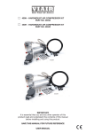
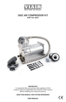
90C COMPRESSOR KIT
PART NO. 00090
92C COMPRESSOR KIT
PART NO. 00092
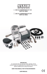
95C COMPRESSOR KIT 12V
PART NO. 00095
95C COMPRESSOR KIT 24V
PART NO. 02495
90C
92C
95C
IMPORTANT:
It is essential that you and any other operator of this
product read and understand the contents of this manual
before installing and using this product.
SAVE THIS MANUAL FOR FUTURE REFERENCE
USER MANUAL
90C - 92C - 95C Air Compressor Kit
IMPORTANT SAFETY INSTRUCTIONS
CAUTION - To reduce risk of electrical shock or electrocution:
- Do not disassemble. Do not attempt repairs or modifications. Refer to qualified service
agencies for all service and repairs.
- Do not use this product in or area where it can fall or be pulled into water or other liquid.
- Do not reach for this product if it has fallen into liquid.
- Use this compressor with 12-volt DC systems only.
- This product should never be left unattended during use.
WARNING - To prevent injury:
- Never allow children to operate this compressor. Close supervision is necessary when this
compressor is being used near children.
- This compressor will become very hot during and immediately after use. Do not touch any part of
this compressor with bare hands, other than the ON/OFF switch, during and immediately after use.
- Do not use this product near flames or explosive materials or where aerosol products are being used.
- Do not operate this product where oxygen is being administered.
- Do not pump anything other than atmospheric air.
- Never use this product while sleepy or drowsy.
- Do not use any tools or attachments without first determining maximum air pressure for that
tool or attachment.
- Never point any air nozzle or air sprayer toward another person or any part of the body.
- Wear safety glasses or goggles when operating this product.
- Use only in well ventilated areas.
INSTALLATION
Please read and follow the installation instructions carefully to avoid injury or damage to the
compressor or your vehicle. Each of our air compressors and parts have been carefully produced
and packaged. Before you begin installation, please familiarize yourself with Installation Parts List
(Fig. 1) of this manual.
Guidelines for Selecting Mounting Location:
The selection of proper mounting location for your air compressor will help ensure a long and
trouble free compressor service life. Please pay close attention to the following guidelines:
1.Select a FLAT, UPRIGHT AND SECURE location where the compressor can be mounted.
2.To maximize air compressor performance, locate compressor as CLOSE TO THE BATTERY
as possible so that length of positive lead wire required is at a minimum. 3. Choose mounting location that is as cool as possible and AWAY FROM HEAT SOURCES.
The cooler the ambient temperature the less chance the compressor will overheat.
4. This compressor is moisture & splash resistant, but NOT WATER PROOF. Do not mount compressor in locations where the unit is likely to come in contact with water.
5. (P/N/ 00092 Only) Select compressor mounting location where air line can be routed from compressor air inlet to remote inlet air filter. Make sure Remote Inlet Air Filter is located in a dry location, away from water splashes.
6. If it is necessary to mount the air compressor further away from the battery, such as inside your vehicle or in the bed of your pickup, use a minimum 16 AWG positive lead wire for
remote installation. (See wire gauge reference chart)
7. Do not mount compressor near areas where flammable liquids are stored.
USER MANUAL
90C - 92C - 95C Air Compressor Kit
MOUNTING AND WIRING
1. Disconnect ground cable from vehicle’s battery.
2. Temporarily position the air compressor in the location where it will be mounted.
3. Route ground wire to the negative post of the battery or to an appropriate grounding point
and cut ground wire to length as needed.
4. Mount air compressor with the four sets of 13/64” (5 mm) bolts, nuts, washers, and locking washers provided. Use of thread sealant recommended.
5. IMPORTANT: Please note, your compressor may have a check valve. DO NOT remove check valve from the unit. 6. Connect compressor’s positive lead wire to one of the leads of your pressure switch. 7. Make sure that your compressor setup is properly fused. For appropriate fuse size, refer to
amp draw of compressor in the specifications section of this manual. 8. Always locate fuse as close as possible to power source. 9. Before connecting to power source, re-check to make sure that all connections
are properly connected.
10. Connect and test compressor system by running the compressor for a short time to build up pressure in your air tank.
11. Once air pressure reaches preset cut out pressure of your pressure switch, the compressor
will shut off. Inspect all air line connections for leaks with soap and water solution.
If a leak is detected, the air line may not be cut squarely or pushed all the way in. Tighten connections if needed.
(Fig. 1) 90C - 92C - 95C Air Compressor Kit Installation Parts List:
A
BCD
E
A. Mounting Bolts (4pcs)
B. Flat Washers (8pcs)
C. Locking Washers (4pcs)
D. Nuts (4pcs)
E. Inlet Air Filter with Filter Element (1pc) (P/N 00092)
(Fig. 2) Compressor
Mounting Hardware
B. Mounting Bolt
C. Flat Washer
D. Locking Washer
E. Nut
K. Vibration Isolator
B
C
K
C
D
E
USER MANUAL
90C - 92C - 95C Air Compressor Kit
OPERATING INSTRUCTIONS
1.IMPORTANT: Always operate the compressor at or below the MAXIMUM PRESSURE RATING of
the compressor. Please refer to Application & Specifications Sections of this manual for details.
2. Always observe the MAXIMUM DUTY CYCLE of the air compressor. Refer to Compressor
Applications and Specifications Sections of this manual for details. Operation exceeding
maximum pressure ratings and/or duty cycle will result in damage to the air compressor. 3. To prevent discharge of your vehicle’s battery, and enhance performance, keep the vehicle’s engine running while using the compressor.
4. Only operate compressor in well ventilated areas.
MAINTENANCE & REPAIRS
1.Periodically check all electrical and fitting connections. Clean and tighten as needed. 2. Periodically check all mounting screws. Tighten as needed.
3. Replace air filter element periodically. Replacement frequency depends on operating frequency
and operating environment. For frequent use in dusty environments, we recommend that you
replace air filter element at least once a month. 4. Regularly clean dust and dirt from compressor cooling fins and motor housing.
5. Your air compressor is equipped with permanently lubricated, maintenance-free motor.
Never try to lubricate compressor.
6. All repairs should be performed by Manufacturer or Manufacturer’s Authorized Service
Agencies only. CAUTION:
Never touch the air compressor or fittings connected to the air compressor with bare hands
during or immediately after use. Leader hose and fittings connected to Leader Hose will become
very hot during and after use. If necessary, wear heat resistant gloves to handle fittings, air line,
and leader hose.
USER MANUAL
90C - 92C - 95C Air Compressor Kit
SPECIFICATIONS
• Part No. 00090 / 90C Air Compressor
Motor Voltage:
Max. Current Consumption: Motor Type:
Max. Working Pressure:
Max. Duty Cycle (@ 72°F & 100 PSI):
Max. Ambient Temperature: Min. Ambient Temperature: Dimensions:
Net Weight:
12 Volts
10 Amps
Permanent Magnetic
120 PSI
9%
158°F
-40°F 5.9”L x 2.1”W x 4.5H”
2.4 Lbs.
• Part No. 00092 / 92C Air Compressor
Motor Voltage:
Max. Current Consumption: Motor Type:
Max. Working Pressure:
Max. Duty Cycle (@ 72°F & 100 PSI):
Max. Ambient Temperature: Min. Ambient Temperature: Dimensions:
Net Weight:
12 Volts
10 Amps
Permanent Magnetic
120 PSI
9%
158°F
-40°F 7.6”L x 2.1”W x 4.5H”
2.4 Lbs.
• Part No. 00095 / 95C 12V Air Compressor
Motor Voltage:
Max. Current Consumption: Motor Type:
Max. Working Pressure:
Max. Duty Cycle (@ 72°F & 100 PSI):
Max. Ambient Temperature: Min. Ambient Temperature: Dimensions:
Net Weight:
12 Volts
10 Amps
Permanent Magnetic
120 PSI
9%
158°F
-40°F 5.4”L x 3.1”W x 4.6H”
2.5 Lbs.
• Part No. 02495 / 95C 24V Air Compressor
Motor Voltage:
Max. Current Consumption: Motor Type:
Max. Working Pressure:
Max. Duty Cycle (@ 72°F & 100 PSI):
Max. Ambient Temperature: Min. Ambient Temperature: Dimensions:
Net Weight:
12 Volts
5 Amps
Permanent Magnetic
120 PSI
9%
158°F
-40°F 5.4”L x 3.1”W x 4.6H”
2.5 Lbs.
USER MANUAL
90C - 92C - 95C Air Compressor Kit
COMPRESSOR APPLICATION GUIDE
To ensure that you get the highest level of satisfaction from your compressor performance, refer to
information below:
VIAIR COMPRESSOR REFERENCE CHART
COMPRESSOR SERIES
DUTY CYCLE
100 SERIES
15%
215 SERIES
17%
225 SERIES
20%
265 SERIES
22%
275 SERIES
25%
300 SERIES
30%
400 SERIES
33%
450 SERIES
100%
500 SERIES
33% 550 SERIES
100% WORKING PRESSURE
130 PSI
150 PSI
150 PSI
150 PSI
150 PSI
150 PSI
150 PSI
150 PSI
150 PSI
150 PSI
ABOUT COMPRESSOR DUTY CYCLE:
Compressor Duty Cycle refers to amount of time a compressor can be operated in a given time
period, at 100 PSI & at a standard ambient temperature of 72°F.
Duty Cycle is commonly expressed as:
Compressor On Time / (Compressor On Time + Off Time)
As an example, a compressor that is rated for 20% duty cycle means that compressor can be
operated at 100 PSI @ 72°F for 8 Minutes and rested for 32 Minutes.
8 min. on / (8 min. on + 32 min. off) = 20% Duty Cycle
DUTY CYCLE REFERENCE CHART
DUTY CYCLE @100PSI / 72°F
15%
17%
20%
22%
25%
30%
33%
100%
MINUTES ON / OFF
6 Min. On / 34 Min. Off
7 Min. On / 30 Min. Off
8 Min. On / 32 Min. Off
9 Min. On / 30 Min. Off
10 Min. On / 30 Min. Off
13 Min. On / 30 Min. Off
15 Min. On / 30 Min. Off
Continuous Duty
ABOUT RATED WORKING PRESSURE:
To ensure trouble free service life of your compressor, always operate compressor within rated
working pressure of the compressor. Never use a pressure switch with a higher cut-off pressure
than compressor’s rated working pressure.
USER MANUAL
90C - 92C - 95C Air Compressor Kit
TROUBLESHOOTING GUIDE:
PROBLEM:
POSSIBLE CAUSE(S)
CORRECTIVE ACTION
Tank pressure drops when 1. Loose drain cock
compressor(s) shut off
2. Check valve leaking
3. Loose connections
1. Tighten drain cock
2. Replace check valve or
compressor
3. Check all connections with
soap and water solution
and tighten
Compressor runs
continuously and air flow
lower than normal
1. Excessive air usage
2. Loose connections
3. Worn piston ring or inlet valve.
4. Clogged air filter element
1. Decrease air usage
2. Check all connections with
soap and water solution
and tighten.
3. Replace compressor
4. Replace air filter element
Compressor runs
continuously causing
safety valve (if equipped)
to open
Excessive moisture in
discharge
1. Faulty pressure switch
2. Defective safety valve
1. Replace pressure switch
2. Replace safety valve
1. Excessive water in air tank
2. High humidity
1. Drain tank, tilt tank to drain.
Drain tank more frequently
2. Move compressor to area
with less humidity, or use
water separator
Compressor will not run
1. No power, or power switch
in OFF position
2. Blown fuse
3. Motor overheats
4. Faulty pressure switch
(if hooked up to a
pressure switch).
1. Make sure compressor
switch is ON
2. Disconnect compressor
from power source, replace
fuse. (Refer to Specifications
section for correct
fuse amperage)
3. Let compressors cool off for
about 30 minutes to allow
thermal overload switch to reset.
4. Replace pressure switch
Thermal overload
protector cuts out
repeatedly
1. Lack of proper ventilation or
ambient temperature is too high
2. Compressor valves failed
1. Move compressor to well
ventilated area, or area with
lower ambient temperature
2. Replace compressor
Excessive knocking
or rattling
1. Loose mounting bolts
2. Worn bearing on eccentric or
motor shaft
3. Cylinder or piston ring is worn
1. Tighten bolts
2. Replace bearing or
piston assembly
3. Replace piston or compressor
CAUTION: NEVER DISASSEMBLE COMPRESSOR WHILE
COMPRESSOR IS PRESSURIZED.
USER MANUAL
90C - 92C - 95C Air Compressor Kit
WIRE GAUGE GUIDE 12-VOLT:
Amp Draw
10
15
20
25
30
40
50
60
WIRE GAUGE GUIDE 24-VOLT:
Length of wire from battery to compressor
10
15
20
25
30
14
12
10
10
10
12
10
10
8
8
10
10
8
6
6
10
8
6
6
6
10
8
6
6
4
8
6
6
4
4
6
6
4
4
2
6
4
4
2
2
Amp Draw
10
15
20
25
30
40
50
60
Length of wire from battery to compressor
10
15
20
25
30
18
16
14
12
12
16
14
12
12
10
14
12
10
10
10
12
12
10
10
10
12
10
10
8
8
10
10
8
6
6
10
8
6
6
6
10
8
6
6
4
SINGLE “C” MODEL
COMPRESSOR WIRING DIAGRAM
Wiring Diagram:
(Fuse Not Included)
12V 40A
Relay
87
30
85
86
Fuse
-
+
Battery
To Keyed
Power Source
Pressure
Switch
LIMITED
15
Edelman WARRANTY:
Irvine,
92618
VIAIRCA
Corporation
warrants this product, when properly installed and under normal conditions of
949-585-0011
use, to be free from defects in workmanship and materials for a period of one year from its original
www.viaircorp.com
Rev.1
date of purchase. To receive warranty service or repair, please contact VIAIR Corporation. Returns should be made within one year of the date of purchase, after a Return Goods Authorization
(RGA) number has been assigned by VIAIR Corporation. To obtain RGA, fax a copy of your receipt
to (949) 585-0188. For complete warranty details, please visit: www.viaircorp.com/warranty
PLEASE NOTE:
THIS WARRANTY COVERS PRODUCT DEFECTS ONLY; IT DOES NOT COVER INCIDENTAL
OR CONSEQUENTIAL DAMAGES AS RESULT OF MISUSE OR ABUSE.
15 EDELMAN • IRVINE, CA 92618
TEL: (949) 585-0011 • FAX: (949) 585-0188
www.viaircorp.com
USER MANUAL