1
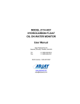
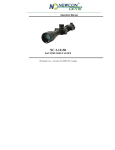
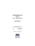
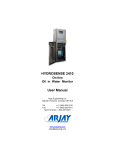
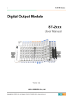
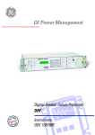
MODEL 2114-OCF OPEN CHANNEL FLOW MONITOR User Manual Technical Support Continental North America Toll Free 1-(800) 387-9487 Ph: +1 (905) 829-2418 Fx: +1 (905) 829-4701 A Product of Arjay Engineering Ltd. Oakville, Ontario, Canada www.ArjayEng.com 2114-OCF Open Channel Flow Monitor Continuous flow monitoring of open channel flumes and weirs Over 30 years of Arjay’s field proven HF capacitance technology has been applied to the 2114-OCF open channel flow monitors. The sensing probe continuously monitors stream levels for conversion to flow outputs. • capacitance technology does not foul or require cleaning • no moving parts • remote alarm unit mounts safely away from the stream 2114-OCF The 2114-OCF sensing probe monitors the capacitance field between the probe and it’s concentric shield. As the level of water increases in the stream, the probe capacitance changes. This level is proportional to flow based on the Manning equations for flumes and weirs. Features and Benefits Technical Specifications - Control Unit • no moving parts • remote electronics via standard twisted pair • available with Intrinsic Safety Barrier for Hazardous Locations • high corrosion resistant Teflon and stainless steel wetted parts • HF capacitance technology does not require routine cleaning • easy calibration and control set-up • display of level, flowrate, and flow totalization • outputs for level, flow and totalization The four line backlit display provides menu driven set-up functions and a display of flowrate and totalization. Operating Temperature Power Input Analog Output Interface Display Alarm Relays Standards Enclosure 0˚C to 50˚C 24 vdc or 110 vac or 220 vac 4-20 mA proportional to flow RS-485 Modbus available backlit display of level, flowrate and totalization 4 x 10 amp, SPDT, dry UL, CSA, CE Type 4X, IP65 Technical Specifications - Probe Operating Temperature Approval All calibration, control relays and power wiring is available at the main control unit. This can be safely mounted up to 1 km away from the stream. 0˚C to 50˚C CSA Class 1, Zone 1 and 2, Div 1 and 2, Groups A,B,C,D (also available with an Intrinsic Barrier option) The unique PMC circuit design, exclusive to Arjay, immediately converts the sensor signal to a frequency pulse for furtherance to the controller. Arjay SS-06 Arjay Engineering Ltd. 2851 Brighton Road Oakville, Ontario Canada L6H 6C9 tel fax N. America email web ++1 905-829-2418 ++1 905-829-4701 1-800-387-9487 [email protected] www.arjayeng.com Model: 2000 Series OCF 2114ocfum23.doc Rev: 2.3 TABLE OF CONTENTS 1.0 2.0 3.0 4.0 5.0 6.0 7.0 INSTRUMENT OVERVIEW ............................................................................................3 1.2 DESCRIPTION...................................................................................................3 INSTALLATION...............................................................................................................5 2.1 GLOSSARY OF SYMBOLS ...............................................................................5 2.2 PROBES ............................................................................................................6 2.3 PROBE INSTALLATION ....................................................................................6 2.4 MECHANICAL INSTALLATION .........................................................................7 2.5 POWER PERMANENT CONNECTION (AC POWERED MODELS ONLY) .....8 2.6 ELECTRICAL INSTALLATION ..........................................................................9 2.7 CONNECTOR TERMINALS: MAX. WORKING VOLTAGES OR CURRENTS 10 STARTUP AND CALIBRATION......................................................................................11 3.1 NOTES ON VALUE ENTRY ..............................................................................11 3.2 POWERUP DISPLAY ........................................................................................11 3.4 MINIMUM SETUP ..............................................................................................12 3.4.1 XMTR VALUES ...................................................................................12 3.4.2 DATA FILTER (SMOOTHING) ............................................................12 3.4.3 SELECT PRIMARY DEVICE TYPE ....................................................13 3.4.4 PRIMARY DEVICE SELECTION TABLE ............................................13 3.4.5 ENGINEERING UNITS .......................................................................13 3.4.6 TAG NUMBER.....................................................................................14 3.4.7 mA SETTINGS ....................................................................................14 3.4.8 RELAY SETTINGS ..............................................................................15 3.4.9 CALIBRATION.....................................................................................16 3.5 TOTALIZATION .................................................................................................18 OPERATION ...................................................................................................................19 4.1 DISPLAY MENU [DISP] .....................................................................................19 4.2 CALIBRATION [CALIB] ......................................................................................19 4.2.1 AUTOMATIC CALIBRATION [CALIB\1] ..............................................20 4.2.2 MANUAL CALIBRATION [CALIB\2] ....................................................20 4.2.3 SLOPE AND OFFSET [CALIB\3] .......................................................21 4.3 CONTROL MENU [CONT]................................................................................21 4.3.1 mA SETTINGS ....................................................................................21 4.3.2 RELAY SETTINGS ..............................................................................21 4.3.3 RELAY SETTINGS SELECTION ........................................................22 4.4 SETUP MENU [SETUP] ...................................................................................23 4.4.1 PMC 2000 (Manual) [SETUP \ 1 \ 2] ...................................................23 4.4.2 DIAGNOSTICS [SETUP \ 2]...............................................................23 4.4.3 SETTINGS MENU [SETUP \ 3] ..........................................................23 CLEANING AND MAINTENANCE ..................................................................................25 5.1 CONTROL UNIT ................................................................................................25 5.2 LEVEL PROBE ..................................................................................................25 TROUBLESHOOTING ....................................................................................................26 CONTROLLER SETTINGS SHEET ...............................................................................27 -2- Model: 2000 Series OCF 2114ocfum23.doc Rev: 2.3 1.0 INSTRUMENT OVERVIEW 1.1 FEATURES 2 Point single point depth calibration Galvanically isolated probe inputs RF Technology Arjay pulse card system for simple, safe, remote control, calibration and maintenance Up to 4 Differential Alarm relays (SPDT 7A contacts) Isolated mA output selectable as Direct / Inverse & 4-20 / 0-20mA output with offset capability Optional RS-485 Modbus protocol No moving parts 1.2 DESCRIPTION The unit senses level using a RF capacitance measurement technique for very high-resolution measurements. A probe mounted to measure the depth of flow in the channel of the primary flow device (weir, flume). The capacitance of this arrangement is directly proportional to the water level in the channel. The 2000 OCF converts the capacitance to depth, then uses the depth to calculate the flowrate based on the primary device type selected. For streams without a primary device, a 5 point profile table of level vs flow can be entered. The 2114-OCF will develop a point to point curve of flow vs level. The user must prepare known flow vs level values prior to entry. Probe input and mA output are galvanically isolated to minimize electrical interference. The 2000 OCF monitor may be located up to one km away from the probe via inexpensive 2 wire shielded cable. The 2000 OCF monitor offers a 20 character by 4 line LCD and 16 key membrane keypad for detailed data displays plus ease of calibration and setup. Flow rate and totalized flow is displayed in user selectable engineering units. In addition a bar graph gives a quick indication of level. RS-485 Network (2 Wire) 2 Wire (shielded) Isolated input Intrinsic Safety Barrier (Optional) PRIMARY FLOW DEVICE CAPACITANCE LEVEL PROBE Isolated 4-20mA Probes upto 1km away 220/115VAC or 24VDC 4 SPDT RELAY CONTACTS BLOCK2k.DRW Figure 1.0 -3- FL OW Model: 2000 Series OCF 2114ocfum23.doc Rev: 2.3 OPERATION The unit senses level using a RF Capacitance measurement technique for very high-resolution measurements. A concentrically shielded probe mounted in the flow channel measures the capacitance. The capacitance of this arrangement is directly proportional to the level of flow in the channel which is used to calculate the flow rate based on the primary flow device selected or table selected. USER INTERFACE Display Keypad Network 4 line X 20 Character LCD with backlight + bar graph. 4x4 Membrane type matrix. RS-485 / modbus protocol PERFORMANCE Range Resolution Accuracy The unit measures capacitance in pF. The resolution figures for Capacitance are guaranteed. Level Measurement figures are for typical applications. Fow accuracies are also a function of the primary device. 0-1000pF recommended for the resolution figures listed below. 0-10,000pF may be measured with less resolution and accuracy. Capacitance: 0.03 % of Full Scale worst case. Typical: 0.01%. Level: 0.02% of Full Scale (6ft concentric shield probe in water) ±0.2% of Full Scale INPUTS 2 wire plus shield connection to an Arjay PMC-2000 module located in any Arjay Capacitance probe head. Installation category I OUTPUTS / RELAYS mA output Relays 0.05% resolution, sourced into 900 Ohms maximum load. up to 4 SPDT 7A/120VAC contacts. Each relay may be set for differential control (hi and low setpoints) Programmable time delay: 0 - 99 seconds. Hi Fail-safe selectable. ELECTRICAL SPECIFICATION Power Fuse 120VAC / 230VAC / 24VDC ±10% (specify at time of order), 15VA max. T160mA, 250VAC. Note: For 24VDC power input, the fuse is a 5mm x 20mm, 1/2A, Fast Blow type. This fuse is installed within the unit and must be installed by qualified personnel only. The equipment belongs to Pollution Degree2, Installation category II MECHANICAL SPECIFICATION Enclosure Dimensions Weight sub plate mount, (optional wall Mount Type Nema 4X enclosure). 5.3” x 8.5” x 2.5” (Wall Mount Nema 4X: 14” x 12” x 7”). 2.2 kg (5lb) max. (Wall Mount Nema 4X: 6kg (13lbs)). ENVIRONMENTAL SPECIFICATION Environment Altitude Temperature RH Indoor or sun/rain shielded use up to 2000m 0 - 50°C sun/rain shielded Max 80% RH for temperatures up to 31°C, decreasing linearly to 50% RH at 40°C. -4- Model: 2000 Series OCF 2.0 2114ocfum23.doc Rev: 2.3 INSTALLATION NOTE: If any damage to the instrument is found, please notify an Arjay Engineering representative as soon as possible prior to installation. All installation must be undertaken by qualified personnel. WARNING: If the equipment is used in a manner not specified by the manufacturer, the protection provided by the equipment may be impaired. 2.1 GLOSSARY OF SYMBOLS Attention, consult accompanying documents Attention, veuillez consulter les documents ci-joints. Protective Earth Terre de protection Fuse Coupe-circuit ; fusible Direct Current (DC) Courant continu L Live N Neutral G Ground Sous tension Neutre Terre Normally open relay contacts Contacts travail Normally closed relay contacts Contacts Repos Power off ArróÕ (mise hors tension) Power on Marche (mise sous tension) CAT I Overvoltage Category I -5- Model: 2000 Series OCF 2.2 2114ocfum23.doc Rev: 2.3 PROBES Capacitance probes may be selected from a variety of styles for use with liquids, liquid interfaces, and granular materials. The probe length is customer specified for the height of material desired to be measured. Usually Teflon coated probes are used. 2.3 PROBE INSTALLATION The probe must be mounted in accordance with the primary flow device type. Here are some general guidelines. 1. The 2000 OCF can be used with a large number of primary device types: flumes and weirs of varying sizes. Each primary flow device stipulates at what point in the channel the depth must be measured. 2. The probe must be mounted up stream from the primary device out of the “Draw Down” area. This is the region where the water level drops as it passes over the primary device. The Draw Down region extends up stream for a length determined by the primary device type and the flow rate. 3. The probe must be mounted in a vertical position. CONC. SHIELDED CAPACITANCE LEVEL PROBE DRAWDOWN AREA MEASURED HEIGHT TO CALCULATE FLOW FLOW ZERO REFERENCE PROBE MOUNTED SO REFERENCE MARK IS AT SAME LEVEL WITH ZERO REF. OF WEIR AND LOCATED BEHIND THE DRAWDOWN AREA. Figure 2.0 -6- Model: 2000 Series OCF 2.4 2114ocfum23.doc Rev: 2.3 MECHANICAL INSTALLATION This unit to be installed within a suitable enclosure in accordance with the Canadian Electrical Code (CEC), or other applicable local and country codes. MODEL 2100, 2300 SERIES LEVEL CONTROLLERS ENCLOSURE FRONT VIEW 4.65" 9.00" www.arjayeng.com Hole diameter 0.150" #6 bolt size (4 places typical) 1- Find a location on a vertical structure to mount unit about eye level in a protected area away from direct condensation. The structure should be able to support the weight of the unit. 2- Mount the unit via bolts into the vertical structure using the 4 mounting holes. The location dimensions are shown above. MECHINST2k.DSF MECHANICAL INSTALLATION AND DIMENSIONS Figure 2.1 -7- Model: 2000 Series OCF 2.5 2114ocfum23.doc Rev: 2.3 POWER PERMANENT CONNECTION (AC POWERED MODELS ONLY) 1) Connection to the building wiring system shall be in accordance with the Canadian Electrical Code (CEC), Part 1 in Canada, the National Electrical Code, ANSI/NFPA 70 in the USA, or the local electrical codes of the country where the equipment is being installed. 2) An external mains switch or external over-current protection / circuit breaker device is required as a disconnect device. This mains disconnect device shall be specified as complying with the requirements of IEC 947-1 and IEC 947-3. 3) The external mains switch shall be in close proximity to the equipment and within easy reach of the operator. The switch shall be marked as the disconnecting device for the equipment and include the symbols to its “ON” and “OFF” positions using the following symbols: POWER ON POWER OFF 4) For supply connections, use wires rated at least 75°C (167°F). 5) The equipment is suitable for connection to a 15A protected branch circuit. 6) Wiring diagram for permanent connection: See Figure 2.2 7) Use copper conductors only. -8- Model: 2000 Series OCF Rev: 2.3 ELECTRICAL INSTALLATION All connections are via plug-in connectors for installation convenience. ! #2 + - #1 + - #2 + - To PMC-2000 card in Arjay level probe head. Shield connected to - terminal at 2xxx only - not connected at PMC-2000 N/C + - #1 + + + - PROBES CAT I N/C + 24VDC input for DC powered models + - ! The network connection is optional for the 2100 series and standard on the 2300 series models and requires an Arjay Central Access Panel (CAP) or Handheld Calibrator for data access. mA OUTS SEE USERMANUAL The 24VDC is the power input for DC powered models. For AC powered models, the power connection is on the bottom of the unit. PLEASE OBSERVE CONNECTION POLARITY AS SHOWN OR DAMAGE MAY RESULT. NET 24V Probe #2 and mA output #2 are not available for series 2100 and 2300 models. Caution: to reduce the risk of fire or electric shock, do not interconnect the outputs of different terminals. 2.6 2114ocfum23.doc + Optional RS-485 Network connection Isolated mA sourced output - not loop powered ! Refer to the manual text for maximum working voltages & currents for these terminals. Connect to Earth Gnd. for DC powered models 250V, T160mA AVAILABLE RELAYS: Model Relays available 2xx0 None 2xx2 Relay 1 & 2 2xx4 Relay 1 - 4 POWER L N RELAY3 RELAY4 RELAY1 RELAY2 G( ) Ground Strap to Enclosure lug AC POWER 120VAC 230VAC Elecinst2k1.dsf L N G L1 L2 G POWER OPTIONS (24VDC, 120 or 230VAC) are specified at time of order See Serial Number Label on unit to determine which power option is installed. ELECTRICAL CONNECTIONS Figure 2.2 -9- Model: 2000 Series OCF 2.7 2114ocfum23.doc Rev: 2.3 CONNECTOR TERMINALS: MAX. WORKING VOLTAGES OR CURRENTS TERMINALS DESCRIPTION MAX. VOLTAGE or CURRENT NET + & - Optional RS-485 communication port 10V between NET+ and NET- 24VDC INPUT Optional 24VDC power input. 24V ±10% between the + and – terminals mA OUTPUT 4-20mA or 0-20mA constant current source. Max. output current: 30mA Max. voltage: 24VDC±10% PROBE INPUT Connection to remote Arjay capacitance probe - 10 - Max. working voltage to Earth Ground: 15VDC, Overvoltage Category I. Model: 2000 Series OCF 3.0 2114ocfum23.doc Rev: 2.3 STARTUP AND CALIBRATION This Section is provided for minimum setup. For a more detailed description of features please refer to Section 4.0. RELAY LEDS: ON = HI ACTING ALARM R1 4 line x 20 char LCD R2 R3 STATUS LED: GRN = OK RED = ERROR R4 STATUS DISPLAY 1 2 3 CAL 4 5 6 CONTROL 7 8 9 . 0 ENTER SETUP www.arjayeng.com DISPLAY CALIB CONTROL SETUP Membrane keypad DISPLAY KEY: Displays Level Information. Also used as backspace in value entry. CALIBRATE KEY: For probe calibration menus. CONTROL KEY: For 4-20mA output and Alarm Relay settings. SETUP KEY: For configuration and diagnostics. USRINT2k.dsf USER INTERFACE Figure 3.0 3.1 NOTES ON VALUE ENTRY When entering in numeric values, the cursor can be backspaced to correct mistakes by pressing the DISPLAY key. This is only true if the cursor is not at the beginning of the displayed value, in which case the DISPLAY menu is entered. Values may be entered with any number of places of decimal. If the entered value is out of the allowed limits, the system displays the limiting value for 2 seconds. During value entry, the capacitance and flow values are still being constantly updated in the background. Apart from the CALIBRATION menu and the DIAGNOSTICS menu, in all other menus, the Alarm relays and the mA output are also updated. 3.2 POWERUP DISPLAY After mechanical and electrical installations of the probe(s) and the controller have been successfully completed, power up the unit. The following startup screen will be displayed for about 3 seconds: - 11 - Model: 2000 Series OCF 2114ocfum23.doc Rev: 2.3 Arjay Engineering Level-Ease 2000 Rev: 3.00 / 2kOCF02 S/N: 001234 The Rev. line displays the Hardware Revision followed by the Software Revision separated with a “/”. The Serial Number is displayed by itself on the bottom line. The values shown above are for example only, actual values may differ. After the startup screen, the LCD should show a screen similar to: OPEN CHANNEL FLOW 0.00 CumD 0.00 cm 0 Cum NOTE: The shown values are for example only. The 2nd line shows the flow rate and depth (above the weir reference point). The flow rate is displayed in the selected engineering flow units. One of 8 engineering units may be selected in the configuration menu as described in the next sub-section. The depth units are fixed in “cm”. The 3rd line shows the accumulated flow in eng. units set by the flow rate units. For example, if Cum D is selected for the flow rate, then the accumulated flow will be in Cum. The 4th line displays a bar graph of the flow rate. The bar graph is scaled between the mA output Zero and Span values. The Status Indicator (see figure 3.0) should be green. If this is red then the LCD displays the kind of System Error. See the troubleshooting guide for details. 3.4 MINIMUM SETUP 3.4.1 XMTR VALUES Press the SETUP key, then 1 for PMC 2000, then 2 for Manual. This menu enters the PMC-2000 level transmitter module’s calibration parameters. These parameters are printed on a label attached to the PMC-2000 transmitter connector located in the probe head enclosure. These values should also be noted down in the SETTINGS table located at the end of this manual. On pressing 2 for Manual: ** PMC 2000 SETUP ** Enter xmtr A value: 0.03316 Enter the PMC-2000 module A value then press Enter. The unit will prompt for the K and C values. Enter these followed by pressing the Enter key in each case. 3.4.2 DATA FILTER (SMOOTHING) Press the SETUP KEY if not already in the Setup menu), then press 3 for Settings, then 1 for Filter. ******SETTINGS****** Enter filter time in seconds: 0.0 Enter the data response time in seconds for the unit to respond to a sudden change followed by the Enter key. For example a 5 second setting means the calculated value of the capacitance and resulting values of depth and flow will take 5 seconds to reach their final values as a result of a sudden change of depth. This parameter is used to minimize fluctuating readings. - 12 - Model: 2000 Series OCF 3.4.3 2114ocfum23.doc Rev: 2.3 SELECT PRIMARY DEVICE TYPE You must select the primary device to be used or the table selection if no primary device is used: 1. Press the SETUP key. From the Setup menu , press 3 for PRIM DEV (primary device). 2. From the table below select the primary device to be entered (o to 23). For example, to select a Contracted Rectangular Weir, select 15. Key in the number and press ENTER. The display will confirm your selection. Press 1 to confirm or 2 to select another. 3. For Contracted Rectangular Weirs, and additional dimension is required: channel width. At the prompt, enter this value in “cm”. Press the ENTER key to enter the value and go back to the main SETUP menu. 4. If a manual table is entered, the flow values must be entered in L/S. The level values must be entered in inches. The software will automatically convert these values to display in the chosen units under normal operation. 3.4.4 PRIMARY DEVICE SELECTION TABLE Selection # 0 1 2 3 4 5 6 7 8 9 10 11 12 13 14 15 16 17 18 19 20 21 22 23 24 3.4.5 Device Type V-NOTCH 22 V-NOTCH 30 V-NOTCH 45 V-NOTCH 60 V-NOTCH 90 PARSHALL 2 PARSHALL 3 PARSHALL 6 PARSHALL 9 PARSHALL 12 PARSHALL 18 PARSHALL 24 PARSHALL 36 PARSHALL 48 PARSHALL 60 RECTANGULAR CONTRACTED RECTANGULAR SUPPRESSED CIPOLLETTI PALMER-BOWLUS 6 PALMER-BOWLUS 8 PALMER-BOWLUS 10 PALMER-BOWLUS 12 PALMER-BOWLUS 15 PALMER-BOWLUS 18 MANUAL TABLE ENTRY ENGINEERING UNITS One of 8 units may be selected. These units affect the displayed readings, alarm values and the mA output zero and span values. If the units are changed, all of these values are re-calculated to the newly chosen units.: - 13 - Model: 2000 Series OCF 2114ocfum23.doc Rev: 2.3 Press the SETUP KEY if not already in the Setup menu), then press 3 for Settings, then 2 for Units: ** SELECT UNITS ** 1-L/S 2-LPM 3-CuFS 4-CumS 5-CumM 6-CumD Current: CumD Press the number for the desired units. MGD = Million Gallons per Day, CuFS = Cubic ft per sec, CumS = Cubic metres per second, CumD = Cubic metres per minute, CumD = Cubic metres per day. The current chosen value is displayed on the bottom line. 3.4.6 TAG NUMBER THE TAG NO.s ARE USED ONLY FOR NETWORK APPLICATIONS AND ARE USUALLY FACTORY SET. To communicate on a network, each controller must have a unique Tag Number (also called node address). Important: if multiple units on a network have the same address, network errors will result. An Arjay Central Access Panel (CAP) is required to communicate with 2000 series level controllers on a network. The CAP allows data to be viewed from and remote calibration / set of any 2000 series level controller on the network from a central location. Press the SETUP KEY if not already in the Setup menu, then press 3 for Settings, then 3 for Tag #. Enter the desired tag number. 3.4.7 mA SETTINGS Press the CONTROL key: **CONTROL SETTINGS** 1-Relay Settings 2-mA Settings Press 2 to setup the mA output: ***SET mA OUT*** Zero (CumD) 0.0 Span (CumD) 20,000 Enter the level in percent for Zero and Span values followed by the Enter key in each case. The values are to be entered in the currently selected units. After the Enter key is pressed for the Span value, the following menu is displayed for additional mA settings: ***SET mA OUT*** Action: Direct Type: 4-20mA Press 1 to change The cursor will be on the Action setting line. Pressing 1 toggles between Direct and Inverse action. Direct action causes the 4mA to be output when the level is at the Zero setting and 20mA to be output when the level is at the Span setting. Inverse action is the reverse of Direct action. Press the ENTER key when done. The cursor now drops to the Type setting line. Pressing 1 toggles between 4-20mA and 0-20mA. The 0-20mA as the name implies, outputs a signal between 0-20mA instead of 4-20mA. The 020mA setting generally offers a little better measurement resolution. - 14 - Model: 2000 Series OCF 3.4.8 2114ocfum23.doc Rev: 2.3 RELAY SETTINGS For help in selecting the relay settings please refer to Sections 4.3.2 - 4.3.4. Press the CONTROL key if not already in the Control Settings menu (see mA Settings display above). The press 1 for Relay Settings: ** RELAY SETTINGS ** 1-Relay1(P) 2-Relay2 3-Relay3 4-Relay4 5-Disable Alrms (ENA) Disable relays. Pressing 5 toggles between Enabling (ENA) and Disabling (DIS) alarms. The current state is displayed on the right extreme of the bottom line of the LCD. A Disable setting will disable Alarm relay alarms even if an Alarm condition exists. The factory default setting is ON (ENA) which allows Alarm relays activation. Relays can be enabled AFTER calibration and setup are complete. Press 1 to setup Relay1. Relay 1 is a pulsed output that is energized for half a second every time a selectable volume flows by. Enter the volume of flow per pulse and press the Enter key: * RELAY SETTINGS * Enter Cum/pulse Value for Relay 1 1000 From the relay setup screen, press 2 to setup Relay2. Relays 2 – 4 are general purpose differential alarm relays. Each must be set up in turn: * RELAY 2 SETTINGS * Action: HI (1 for LO) Flsafe: OFF(1 for ON) Next select the Alarm Action by pressing 1 to toggle between High and Low action. See Section 4.3.2 – 4.3.4 for help in selecting this value. Press ENTER after selecting Action. Next select the Failsafe type by pressing 1 to toggle between On and Off. See Section 4.3.2 – 4.3.4 for help in selecting this value. Press ENTER after selecting the Failsafe type. After selecting the Failsafe setting the following menu is displayed.: * RELAY 2 SETTINGS * Hiset (CumD) 15,000 Loset (CumD) 12,000 On Delay (sec): 0 Enter the High and Low alarm (Hiset and Loset) values in percent level. Press Enter after each entry. If Differential control is not desired then set the High and Low alarms to the same value. Finally, set the ON delay in seconds. This is how long an alarm condition must exist before the corresponding relay is switched to an alarm condition. - 15 - Model: 2000 Series OCF 2114ocfum23.doc Rev: 2.3 The following table shows the effect of the Relay Action and Failsafe settings. Relay Action Failsafe Setting Effect High No Alarm condition when flow rate rises above the High Setpoint for at least the alarm delay period. Alarm condition remains active until the flow rate drops below the Low Setpoint. No action is taken when the flow rate is between the High and Low Setpoints. In the alarm condition, the corresponding alarm LED is turned ON, and the relay is energized. High Yes Alarm condition set and reset as above. In the alarm condition, the corresponding alarm LED is turned ON, but the relay is de-energized. Low No Alarm condition when flow rate drops below the Low Setpoint for at least the alarm delay period. Alarm condition remains active until the flow rate rises above the High Setpoint. No action is taken when the flow rate is between the High and Low Setpoints. In the alarm condition, the corresponding alarm LED is turned ON, and the relay is energized. Low Yes Alarm condition set and reset as above. In the alarm condition, the corresponding alarm LED is turned ON, but the relay is de-energized. The Relay Settings menu is now displayed from which other relays may be selected to be set up. Set the remaining relays 2 – 4 in the same way. Note: For models 2xx0 and 2xx2 which have 0 and 2 relays respectively, the front panel LED's are still present for visual indication of alarms even though the corresponding relays are not installed. 3.4.9 CALIBRATION The 2000-OCF is calibrated in “cm”. Calibration ensures the 2000-OCF correctly reads the water height “H” above the primary device’s reference point. There are a number of ways to calibrate the unit. 1. Auto cal 2 point 2. Auto cal 1 point 3. Manual Cal 4. Direct Slope and Offset entry. 2 Point Auto Cal: This method is a 2-point procedure. It is typically done at least once. For convenience it may be performed using a bucket of water. The procedure involves subjecting the capacitance depth probe to 2 known depths. A two point Auto cal procedure is typically done the first time. Thereafter, the calibration can be trimmed using a 1 point Auto cal. 1 Point Auto Cal: This method is a single point procedure. It is typically done after a successful 2 point Auto cal. For example if the displayed depth is10cm, but the actual depth is 9cm, then the 1 Point Auto cal can trim this by simply entering the current (true) depth i.e. 9cm in this case. Alternatively, if the - 16 - Model: 2000 Series OCF 2114ocfum23.doc Rev: 2.3 actual flow rate is known, then the theoretical depth may be determined using tables for the particular primary flow device being used. This depth may be entered in the 1 Point Auto Cal to trim the calibration. Manual Cal: This is only done if 2 depth points and their corresponding capacitance values from the depth probe are known. This information is captured after a successful 2 point Auto cal. 2 POINT AUTO CAL PROCEDURE Press the CALIBRATION key *** CALIBRATION **** 1-Auto 1pt 2-Manual 3-Auto 2pt 4-Slp/Off 5-Clear Accum Press 3 for 2 point Auto Cal. Make a reference mark on the capacitance probe at a distance from the bottom of the probe so that this reference point can be located at the same level as the reference level of the primary device (see Figure) Fill a bucket or container at least 30cm deep with water. The level probe may also be calibrated in its installed position in the flow channel, however, it will be necessary to move the probe up / down during calibration. Lower the capacitance probe in the bucket or channel up to the zero reference point. Hold the probe in place to keep it steady. Enter 00.0 at the keypad and press ENTER. Lower the capacitance probe by an accurately measured distance further into the water (e.g., another 30cm). Enter this further distance (e.g. 30) as the 2nd. point and press the ENTER key. This completes calibration. THIS CONCLUDES THE 2 POINT CALIBRATION PROCEDURE. 1st CAL POINT Enter depth as 0.00"in cm 2nd. POINT Enter depth as D"in cm CAPACITANCE PROBE D Figure 3.1 - 17 - Model: 2000 Series OCF 2114ocfum23.doc Rev: 2.3 1 POINT AUTO CAL PROCEDURE This is a single point procedure. It assumes a 2 point calibration has already been successfully done. The object of this type of calibration is to trim the displayed depth while the pressures sensor is in its installed position. 1. Press the CALIBRATION key to enter the main calibration menu, then 1 for 1 point Auto cal. 2. Accurately measure the depth D of water above the reference point on the level probe. This is also the depth of the water above reference point of the primary device. Enter this value followed by the ENTER key. THIS CONCLUDES THE 1 POINT CALIBRATION PROCEDURE. 3.5 TOTALIZATION 1. The unit will totalize flow as long as a flow rate input exists. To reset to “0”, press the CALIB key. Press 5 for ClrAcc (Clear Accumulation). The display will ask you to confirm that you want to reset the totalizer. If yes, press ENTER. then press DISPLAY. If no, press DISPLAY directly. THIS COMPLETES THE SETUP AND CALIBRATION PROCEDURE NO FURTHER SETUP OR CONFIGURATION IS REQUIRED THE NEXT SECTION (4) IS FOR REFERENCE ONLY - 18 - Model: 2000 Series OCF 4.0 2114ocfum23.doc Rev: 2.3 OPERATION IN THE FOLLOWING TEXT A MENU WILL BE DISPLAYED AS A PATH. FOR EXAMPLE THE AUTOCAL MENU: [CALIB\ 1]. (CALIB key then 1 for AUTOCAL). SETTINGS MENU: [SETUP\3] (SETUP key then 3 for SETTINGS). The 2000 OCF Monitor uses a high precision and highly repeatable RF technique to measure capacitance, which in turn is used to calculate depth and then flow rate. A capacitor is formed by the Teflon sheathed level probe and the stainless steel concentric shield around it. The capacitance of this arrangement changes in proportion to the level of the water in which it is immersed so the depth of the water in the channel may be calculated. The depth is related to the flow rate for any primary flow device, so the flow rate is then calculated from the depth. All Level-Ease 2000 Series Controllers and Transmitters are intelligent and can perform a number of tasks simultaneously (multitasking software). This means that even while in another menu, the capacitance is always be measured in the background. For example if the Filter value is being set in the SETTINGS submenu (SETUP\SETTINGS menu), the level value, relay alarms and mA outputs are still being updated. This is important since keypad entries are typically slow and sometimes an operator might forget to return the unit to the normal DISPLAY menu: in this case Alarm relays and mA output are still updated. In some menus however, the mA output and or the Alarm Relays are not updated on purpose; for example while in the calibration menu, the unit assumes that the unit is being calibrated and so the calculated level may be erroneous. In this case, the mA and Alarm Relays are set to the inactive states. Periodically, (every 5-10 seconds) the unit does a self-diagnostic. If major errors are found they are displayed on the LCD. These error messages take precedence over the flow information in the DISPLAY menu ONLY. All other menus may be entered and parameters viewed or changed. In case of errors, this allows the user to enter the DIAGNOSTICS menu and check the capacitance or frequency etc. 4.1 DISPLAY MENU [DISP] This is the default or normal operating screen. It shows: OPEN CHANNEL FLOW 7,500 CumD 2 cm 32,000 Cum The 2nd line shows the depth of water in “cm” and the flow rate in the chosen flow units. The 3rd line shows the totalized flow. The 4th line shows a bar graph of the flow scaled between the 4-20mA output zero and span values. The resolution is 5%. 4.2 CALIBRATION [CALIB] The 2000-OCF is calibrated in “cm”. Calibration ensures the 2000-OCF correctly reads the water height “H” above the primary device’s reference point. The flow rate is automatically calculated from the depth. There are a number of ways to calibrate the unit. 1. 2. 3. 4. Auto cal 2 point Auto cal 1 point Manual Cal Direct Slope and Offset entry. *** CALIBRATION **** 1-Auto 1pt 2-Manual 3-Auto 2pt 4-Slp/Off 5-Clear Accum - 19 - Model: 2000 Series OCF 2114ocfum23.doc Rev: 2.3 Note: all depth values mentioned below refer to the depth of the water above the reference level of the primary flow device. For ease of calibration, a reference mark is made on the level probe which is then mounted so the probe reference is at the same level as the primary device reference level. See Figure 2.0 in the installation section for details. 4.2.1 AUTOMATIC CALIBRATION [CALIB\1] This is typically done for a new installation. It involves entering the independently and ACCURATELY MEASURED depth of water above the reference point of the primary flow device in the channel at 2 different points. The unit then calculates 2 parameters: SLOPE and OFFSET by correlating the 2 depth values with the corresponding measured capacitance. The SLOPE is the change in capacitance in pF per inch change in level. The OFFSET is the calculated empty vessel capacitance in pF. The Automatic Calibration procedure is already described in Section 3.4.9. The first calibration point is generally 0 cm of depth. This is most easily done by marking a reference point on the probe, which when installed will be in level with the reference point of the primary device. For weirs the reference point is the lowest edge or lip of the weir. For Flumes it is typically the channel floor at a desinated point in the channel. The second point is generally the max. depth of flow expected above the primary device reference level. NOTE: The accuracy of the calibration depends in large part on the accuracy of the 2 measured levels entered during calibration. The resolution of measurement should be 2 decimal places to get the best accuracy. This is also why a minimum of 10% change in depth is recommended between the 2 calibration points, since the larger the difference, the less affect the inaccuracies of entered levels has on the calibration. For example, a 1% error in entered values over a 10% change translates to a 10% error at Full Scale (100%). NOTE: if the SLOPE and OFFSET parameters are already known, they may be entered directly by selecting SLOPE/OFF (item 3 from the Cal menu). This can save a lot of time. 4.2.2 MANUAL CALIBRATION [CALIB\2] This option is used to fine-tune the SLOPE and OFFSET values after a successful Automatic Calibration or when the capacitance at 2 differing depths is known. For example if the capacitance and corresponding depths in “cm” have been recorded over some time then these can be used to recalibrate the unit by using two levels which are furthest apart (and their corresponding capacitance values). The procedure is as follows: At any time, to view the measured capacitance: Press the SETUP key then 2 for Diags: Read the capacitance in pF on the 2nd line from the top. Determine the actual depth in “cm” above the primary device point reference level (same as probe reference point) : (2 places of decimal accuracy) The above steps must be repeated for one other depth, which is different from the first by at least 10%. This can be either done in a vessel or in the channel by raising or lowering the probe in the water. TO CALIBRATE USING MANUAL CALIBRATION: Press the CALIBRATION key to get to the CALIBRATION menu then 2 for Manual. Enter the 1st depth in “cm” (2 decimal places) then press the Enter key. Enter the 1st corresponding capacitance value. - 20 - Model: 2000 Series OCF 2114ocfum23.doc Rev: 2.3 The unit then prompts for the 2nd depth and the 2nd capacitance. After entering these values the unit will calculate the SLOPE and OFFSET. Use the Slope/Off menu item described below to view and record these values for future reference. 4.2.3 SLOPE AND OFFSET [CALIB\3] Use this feature to view and or modify the SLOPE and OFFSET calibration values directly. 4.3 Press the CALIBRATION key to enter the CALIBRATION menu then 3 for Slope/Off. Enter the desired SLOPE and OFFSET. If no change is desired just press the Enter key in each case or a Menu key to go to another menu such as the DISPLAY menu. CONTROL MENU [CONT] The CONTROL menu allows the setup of the mA output and the Control Relays. NOTE: The Control Relays and the mA output are set to their OFF states when in the CALIBRATION menu [CALIB]. In the DIAGNOSTICS menu [FUNCTION \ 2], the mA output may be set manually by the operator to 4mA or 20mA. In this case the mA output does not reflect the level value. 4.3.1 mA SETTINGS The mA output Zero and Span settings may be set anywhere within the measurement range. For example, if the Zero is set to 100CumD and the Span is set at 20,000CumD then the mA output is scaled between these two points with the mA output indicating low level at 100CumD and high level at 20,000CumD. The mA output may also be set to Direct or Inverse Acting. In Direct Action, the mA output is 4mA when the level is at the Zero level and 20mA when at the Span level. In Inverse Action, the mA output is 20mA when the level is at the Zero level and 4mA when at the Span level. 4.3.2 RELAY SETTINGS Arjay Level controllers may be used to control devices such as pumps, valves and other equipment based on flow rate values. Relay 1 is fixed as a totalizer output. It is energized for about half a second every time a selectable volume flows by. The units of totalized flow depend on the flow rate units selected. For CumD flow units, the totalizer value is Cum. Relays 2 through 4 allow 5 parameters: 1. HIGH ALARM (or CONTROL) POINT. This value is specified in flow rate. Above this value, relay action is taken depending on the Relay Action and Failsafe settings. 2. LOW ALARM (or CONTROL) POINT. This value should be less than the High control point. Below this value, relay action is taken depending on the Relay Action and Failsafe settings. 3. RELAY ACTION . High or Low Action. Selecting high action will energize the relay when the flow exceeds the high control point for at least the time delay period. An LED on the front panel for the appropriate relay indicates the alarm condition. The relay is de-energized (with no delay) when the flow falls below the low control point. Selecting low action will energize the relay when the flow falls below the low control point for at least the time delay period. The relay is de-energized (with no delay) when the level rises above the high control point. 4. FAILSAFE. Failsafe typically means that the relay is normally (when not in an alarm condition) held in an energized state. In an alarm condition, the relay is de-energized i.e. identical to when the - 21 - Model: 2000 Series OCF 2114ocfum23.doc Rev: 2.3 instrument power is shut off. The rationale is that the alarm condition should match the Power Fail condition. 5. RELAY DELAY. Minimum time in seconds for an alarm to exist before the corresponding relay is set to its alarm state. The relay alarm state depends on the Relay Action and Failsafe settings. 4.3.3 RELAY SETTINGS SELECTION 1. Identify the positive action required in the control application such as turning on a pump, opening a valve, or sounding an alarm. Note: the time delay is applied to the start of the positive action; also, the corresponding LED is turned on to indicate the positive action. 2. Identify if Fail Safe condition is required in an alarm condition. For control applications (relay used to control pump etc.), the positive action may also be viewed as the opposite state desired in the event of a power or instrument failure. For alarm applications (relay used to indicate an abnormal condition such as a high flow rate), the positive action may be the same state desired in the event of a power or instrument failure. 3. Identify the type of relay action required: if the positive action is required when the flow exceeds the high control point then select High Action for the relay. If the positive action is required when the flow falls below the low control point then select Low Action. 4. Identify the relay contacts to use (either Normally Open or Normally Closed). The contacts used are dictated by the failsafe setting and if the positive action requires the application of power or removal of power to the controlled device. The following table summarizes the settings for all possible requirements: # DESIRED CONTACT CONDITIONS DO THIS BELOW ABOVE INSTRUM. Or FAILSAFE RELAY USE LOW SETPOINT HIGH SETPOINT PWR FAILURE SETTING ACTION CONTACTS 1 Open Closed (PA) Open No High Acting NO 2 Open Closed (PA) Closed Yes High Acting NC 3 Closed (PA) Open Open No Low Acting NO 4 Closed (PA) Open Closed Yes Low Acting NC 5 Open (PA) Closed Closed No Low Acting NO 6 Open (PA) Closed Open Yes Low Acting NC 7 Closed Open (PA) Closed No High Acting NO 8 Closed Open (PA) Open Yes High Acting NC (PA) = positive action desired such as turning on a pump. Conditions 1, 3, 5, 7 are typically for control applications where the positive action i.e. turning on a pump, should be shut off during a power failure to the Arjay 2000 OCFunit. Conditions 2, 4, 6, 8 are typically for alarm applications where the positive action i.e. sounding an alarm if the flow is at a high level, should also be in place during a power failure to the Arjay 2000 OCFunit. - 22 - Model: 2000 Series OCF 4.4 2114ocfum23.doc SETUP MENU Rev: 2.3 [SETUP] The SETUP menu is used for one-time setup and for Diagnostics. ********SETUP******** 1-PMC 2000 2-Diags 3-Settings 4.4.1 PMC 2000 (Manual) [SETUP \ 1 \ 2] This menu is to calibrate the 2000 series controller for the particular PMC-2000 level transmitter module located at the probe head. There are 3 calibration parameters: A, K, C. These values are used to calculate the capacitance from the frequency signal received from the PMC-2000. The parameters may be calibrated manually or automatically. Automatic Calibration is performed at the factory on each PMC2000 module. A label listing the A, K, C values is then affixed to the PMC-2000 connector. AUTOMATIC CALIBRATION IS ONLY TO BE PERFORMED BY AUTHORIZED PERSONNEL AND IS BEYOND THE SCOPE OF THIS MANUAL. IF PROBLEMS ARE ENCOUNTERED, OR IF THE A, K, C VALUES ARE NOT KNOWN, PLEASE CONTACT AN ARJAY REPRESENTATIVE. Manual entry of the A, K, and C values is described in Section 3.4.1 4.4.2 DIAGNOSTICS [SETUP \ 2] This menu displays the received frequency signal from the PMC-2000 module at the probe head and the calculated capacitance. Both of these values are useful in determining calibration or performance problems. ****DIAGNOSTICS***** 12.04pF 4461.48Hz 1-4mA 2-20mA 3-Other Pressing key 1 forces the mA output to 4mA. Similarly pressing key 2 forces the mA output to 20mA. Any other value between 0 and 20 may be set by pressing 3 for “Other” then entering the desired mA output value. This feature is convenient to check the performance of external recorders or PLC’s, which read the mA output. The mA output reverts back to its actual level when the normal Display Menu is selected. 4.4.3 SETTINGS MENU [SETUP \ 3] This menu sets the digital filter and the engineering units. In addition the mA output may be trimmed for maximum accuracy. Also,Software revision may be viewed: ****** SETTINGS ****** 1-Filter 2-Units 3-Prm Dev 4-mA Trim 2114 Rev:2kOCF04 mA TRIM: This procedure trims the mA output for maximum accuracy by compensating for the mA output circuitry tolerances. THIS PROCEDURE IS PERFORMED ON EVERY TRANSMITTER AT THE FACTORY AND IS TO BE PERFORMED BY AUTHORIZED PERSONNEL ONLY. IF IMPROPERLY DONE, THE ACCURACY OF THE mA OUTPUT IS AFFECTED. Under certain conditions this procedure may be undertaken in the field with Arjay’s permission: Press the SETUP key, then 3 for Settings and then 4 for mA Trim. The unit will put out what it thinks is 20.0mA. - 23 - Model: 2000 Series OCF 2114ocfum23.doc Rev: 2.3 Disconnect any load connected to the mA output of the transmitter. With an ACCURATE MULTIMETER MEASURE THE mA OUTPUT. The Multimeter should have at least one place of decimal. Enter this value at the prompt and press the Enter key. A maximum tolerance adjustment of 3% is allowed i.e. the entered value must be in the range of 19.4mA to 20.6mA. If a value out of this range is entered an error is flashed on the screen. If this occurs, contact an Arjay representative for assistance. FILTER, ENGINEERING UNITS: These settings are described in Section 3. - 24 - Model: 2000 Series OCF 2114ocfum23.doc 5.0 CLEANING AND MAINTENANCE 5.1 CONTROL UNIT Rev: 2.3 The 2000 series level controllers do not require specific maintenance. There are no moving parts. If required, the units may be cleaned with a clean damp cloth. Make sure power is shut off before bringing anything wet or damp in contact with the unit. Do not use organic solvents which may damage or dissolve the plastic label or silkscreen text. Spray cleaners should also be avoided to prevent damage to components within the enclosure. 5.2 LEVEL PROBE Periodically the level probe may be washed down with water to prevent buildup. Only the probe and not the probe head (enclosure a the top of the probe) should be cleaned. Direct the water through the holes / slots in the shield so the probe inside the shield can be cleaned. - 25 - Model: 2000 Series OCF 6.0 2114ocfum23.doc Rev: 2.3 TROUBLESHOOTING CONDITION DISPLAY SCREEN SHOWS: Error: No Xmtr Signal DISPLAY SCREEN SHOWS: Error: Setup Values Bad DO THIS The unit is not receiving a frequency signal from the remote PMC-2000 level transmitter in the probe head: Check wiring. If wiring checks out: call Arjay technical support. An adjustment may be made at the controller. This indicates that at least one of the calibration or setup parameters has been corrupted. Compare ALL parameters with the table in Section 6 to find out which one. Call Arjay technical support. The calculated capacitance is out of the legal ranges: Check if the A, K, C values entered correspond to t he A,K,C values of the PMC-2000 transmitter. DISPLAY SCREEN SHOWS: Error: pF out of range Check the integrity of the Teflon sheath of the probe. If this has beem damaged, water could cause an electrical short circuit between the probe within the Teflon sheath and the ground reference. In this case, a very high capacitance is usually registered. Check the Xmtr frequency in the Diagnostics menu. If the frequency is much below 19,00 Hz then a short circuit should be suspected. To confirm: open the probe head and disconnect the blue wire from the probe to the PMC-2000. Using a Digital Ohm meter, measure the resistance between the metal enclosure and the probe tip (or end of now disconnected blue wire). Make sure that fingers and hands do not touch the metal portion of the probes of the Ohm meter since this could show a lower resistance: 1 – 10 Mohms. The reading for a normal probe should be infinite or “OL” on a digital Ohm meter. Contact an Arjay representative. Make sure the correct primary device has been selected. The flow reading is erratic or unstable Check the slope value (Calibration menu \ slope-offset). If this is lower than about 1 pF, then recalibrate. The slope should be around 4 pF per inch for water for a probe with a 2 inch concentric shield. Check if the probe is being splashed by incoming water, or if there are moving parts (especially metallic) close to the probe. If this is true, then try increasing the Filter time setting. Readings are not accurate as the level moves away from the calibration point (points) Make sure the correct primary device has been selected. Recalibrate the unit. - 26 - Model: 2000 Series OCF 7.0 2114ocfum23.doc Rev: 2.3 CONTROLLER SETTINGS SHEET Checked by Model Number Serial Number Software Rev. PARAMETER DESCRIPTION FACTORY SETTING Primary Device The flow Primary Device type. Weirs and Flumes of various types and sizes are supported Flow Units Eng. units chosen to display flow information in addition to the depth in “cm”. Probe A value Probe PMC-2000 level transmitter calibration value Probe K value Probe PMC-2000 level transmitter calibration value Probe C value Probe PMC-2000 level transmitter calibration value Slope Result of a successful Calibration: Capacitance change per inch change. Used to calculate the depth in “cm” from capacitance and flow rate from depth and primary device type. Offset Result of a successful Calibration: Calculated capacitance of an empty vessel. Used to calculate the level in % and Eng. Used to calculate the depth in “cm” from capacitance and flow rate from depth and primary device type. Zero Zero Level value for mA output Span Full Scale Level value for mA output. mA Action Direct (20mA when level at Span) or Inverse (4mA when level is at Span Relay1 Volume per pulse Alarm Relay 1 will pulse for half a second every time this amount of flow is measured. Relay2 Hi Set Alarm Relay 2 High Setpoint: Alarm condition if flow is above this value. Relay2 Lo Set Alarm Relay 2 Low Setpoint: Alarm conditions cleared if flow is below this value. Relay2 Action Set for high or low acting (see Sections 4.3.24.3.4) High Relay2 Failsafe Set for Failsafe or Non Failsafe Off Relay 2 Alarm Delay See Relay 1 Alarm Delay description. 0 sec Relay3 Hi Set Alarm Relay 3 High Setpoint: Alarm condition if flow is above this value. Relay3 Lo Set Alarm Relay 3 Low Setpoint: Alarm conditions cleared if flow is below this value. - 27 - 0.0 DIR USER SETTTING Model: 2000 Series OCF PARAMETER 2114ocfum23.doc DESCRIPTION Rev: 2.3 FACTORY SETTING Relay3 Action Set for high or low acting (see Sections 4.3.2 – 4.3.4 for details) High Relay3 Failsafe Set for Failsafe or Non Failsafe Off Relay4 Hi Set Alarm Relay 4 High Setpoint: Alarm condition if flow is above this value. Relay4 Lo Set Alarm Relay 4 Low Setpoint: Alarm conditions cleared if flow is below this value. Relay4 Action Set for high or low acting (see Sections 4.3.2 – 4.3.4 for details) High Relay4 Failsafe Set for Failsafe or Non Failsafe Off Alarm Enable Master Alarm Relay Enable: If Off this will prevent relays from being reflecting the Alarm condition. The relay will remain in the non alarm condition base on the Fail-safe switch setting on the relay modules ON Filter Digital Filter response time in seconds. Used to smooth out level fluctuations caused by splashing etc. 0.0 - 28 - USER SETTTING