1
High Performance Multifunctional Inverters
• !"#$ %
"&' ( • ) % ( ) ( ( "& ( • ( ! * +,- . / . ) &
( •
•
0 ( ,
+,- ( 1*,- • !" • 0 / 0 / • #$ " ( % %
$ ) % $ %
2 (
%
• % ) 3 4 $ 4 • & • " $
• • . ) 5 "& /
. 6 • ' 1 7˚5
0 %
) 6 868
( ) • ' $ *+((#,
) %
955:$ %
% 6#5:$
6 % ( • ' *+(,
*&, ) 95$ ' 95 ;
% 95
• ' *+(,
*&, 2 95$ ) ( ( " 23;6 • - 0 0 $ " ) ( 0 ) ( !"#$
• " )" 2 $ 25
;6450!; $ 2
! "#
$% &'!'(' )*% &'!'('+
,-. / 0 2 % $ 695
2 • + ) 3 25 ;6450!; • + %
7 ) 9
Maximum Engineering for Global Advantage
• " *
• ) ) ( $ 6 7
) ( !"#$
• /
/ -
• &
2 • %
/ &
• / ( (
(% (
- • / <
) = 9 FUJI INVERTERS
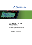
With the flexibility and functionality to support a wide range of
applications on all types of mechanical equipment, the FRENIC-MEGA
takes core capability, responsiveness, environmental awareness, and
easy maintenance to the next level.
$. . ##.
$. "# + '! 1 '2 3 + ),
MEH642b
Improved control performance
Easy maintainance
Applicable control methods: PG vector
control, sensorless vector control, dynamic
torque vector control, and V/f control
Improved performance of current response
and speed response (vector control)
Improved durability in overload operation
Maintenance warning signal output
Use of parts of a longer life cycle
(Designed life: 10 years)
(Main circuit capacitor, electrolytic capacitor,
HD (High duty) spec: 200% for 3 sec / 150% for 1 min
cooling fan)
: For general industry
MD (Middle duty) spec: 150% for 1 min
: For constant torque
applications
LD (Low duty) spec: 120% for 1 min
: For fans and
pumps applications
Maximum Engineering for Global Advantage
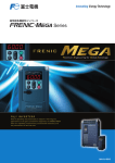
Two types of keypads are available for FRENIC-MEGA: the multi-function
keypad and the keypad with USB port. You can select and use the keypad
that meets your application needs.
Environmental
adaptation
Various applications
Various functions that accommodate a
wide range of applications
Great model variation meeting customers’
needs
Example: Breakage detection by braking transistor,
-Basic type
-EMC filter built-in type
improved reliability of brake signals, and operation at
a specified ratio
Compliance with RoHS Directives (planned)
Expanded capacity of the brake circuit
built-in model
Improved resistance to the environmental
impact
(Standard-equipped for 22kW or smaller models)
FRENIC-MEGA
Variations
Warranty
Options
Various network support
Basic Wiring Diagram
Common Specifications
applications
With the flexibility and functionality to support a wide range of
applications on all types of mechanical equipment, the FRENIC-MEGA
takes core capability, responsiveness, environmental awareness, and
easy maintenance to the next level.
Terminal Functions
FUJI INVERTERS
A multi-function keypad(option)
Function Settings
Maximum Engineering for Global Advantage
Keypad with a USB connector(option)
External Dimensions
FRENIC-MEGA, the inverter with the highest performance in the industry,
is about to redefine the common sense of general-purpose inverters.
Now, it is ready to answer your needs.
Model Variations
FRENIC-MEGA has been developed to use with a variety of equipment
by improving the basic performance,
meeting the requirements for various applications, achieving easy maintenance,
and enhancing the resistance to the environmental impacts.
Keypad Operations
Maximum Engineering for Global Advantage
Inverter Support Loader
High Performance Multifunctional Inverters
FRENIC-MEGA is a high performance, multifunctional inverter
Fuji Electric has developed by gathering the best of its technologies.
With our own state-of-the-art technology, the control performance has evolved to a new dimension.
Standard Specifications
The performance,
reaching the peak in the industry
Characteristics
Maximum Engineering for Global Advantage
FRENIC-MEGA
+
+
Multi-function keypad
Keypad with USB port
─2─
─3─
Model Variations
Keypad Operations
1
Dancer control function optimum for winding control
3, 1) 8 :! , 8
, (: 6 8 : ( ,
( - B , 1) : 0 8 , 8
: , ! , 6 , -
Ratio operation
Improved reaction to the fluctuation of impact load
Fuji’s original dynamic torque vector control has further evolved.
= , ! 8 , 8 0, , ( 8 8 ( , 8 ,
(. :8 ( 0 !- 3, > ,, ( " 8 0 (
-?@>3
"
$
$
/, 6: ( , 8
8 , , 8- , (. > , ( , 0, , 8:- 3, ( :
( , , : , ,-
5.
$
$
150ms
150ms
4
5. , ; $-$6/ <
3, 8 ( , 0, , . ! :! . ,
( ( 8 0,
8 - 3, 8 , (( !
( , , , 8! ,78 :! " ( ? $" ( 3, 8: 0 ( , D( @) @, ! ) ! *) *0 ! 78 + " ( ? $" ( 7 ,8! $" ( 7 " ( 7 , #$"
!
#"
!
%( &"
! 2 ! . % "
PG option card for positioning control
Quicker response to the operation commands
3, , , , :, - %5HD 5A , (, , ,
,8 , ! 3, ( (( 8 , , ! (( 8 ( , ( -
5.
─4─
Approx. 4ms
7 3
. % 7 7H
D .- 18 .- 9
% ,
:! .- ) 1 (
.- 1 * +
, ( , -
More functions are available to meet various requirements
8 ,, 0,
! ,, B0 (0 8
( 1> : :( 0
(0 - ? H 4( ? )! ( ( $ B ( , ,
9 B, -4 - I ) ( , 1) (: 6
The customized logic interface function is adopted in the inverter body. (Available soon)
3, ( : ( , , ,,! , , ( , 8! ,- =! : ( , 8 1%
1A 8 , ! , :
6:! 8- B, :! , ( 0 : ,( , ( ! 5. . , 6 !
6
7:+ : 6
= 8!
8 % *0 Thorough protection of the braking circuit
5A , : , , 8
, -
/
,
. ' MEGA World Keeps Expanding
Expanded capacity for the braking circuit built-in type
:6 : , 6/ - 3, 8 : , , ,
8 , 8 8! ,
3, I-$6/ :6
-
E 3, 8 0, : :6 8: ( ?6/ 6/ -
!
. 3, 8 , :6 :! ,
:6 - The inverter outputs an
exclusive signal on detection of the braking transistor
abnormality. ( , (( , 0 !
8 ( , 8- /, , , 0 , ((G , , :6
-
*
Improved durability in overload operation
% #$"
!
7 8 3, , ( ! 8 (
+ 0 8! !- 3, ( ,
. , 0 . : ( ! - 7 , , , , 8 , 8! , , 8! : + !-
* 4 : ! :! 3, 6 : (! , , 5D*=
DD=
3, ( 8:
, ( -
D
D
=B
=B
%
Introducing servo lock function (PG option card).
B 1 %( 1 ;*B<
3 3, ( (( 8 + , , :6
0, , , 8! , :! ( , - 3, ( ,( 0,
.! , ,
- 3, ! 0 : :! ,
─5─
Inverter Support Loader
1*D
Standard Specifications
E 3, !E 3, :8 ( ! 8! ,
8 ( -
5A
Common Specifications
B B @>
B ! C-$"
D $@>
3 ! C"
: , 0, , , ( 8 ( , . 6@>
Basic Wiring Diagram
B $
B @>
B ! C-"
D $@>
3 ! C"
3, :! ( , :6
0 ( , 8 8! D8! , 8 , ( ! ,8
: 0, , :6
- =! 8 , 0
8 , :6 :
+ !-
The pulse train input function is equipped as
standard.
Terminal Functions
'( ( , , ,, , , !
8 6 0
Function Settings
Speed sensor-less vector control
5(( 8 8 ,,! ( , Optimum function for preventing an object from slipping down
External Dimensions
PG vector control
Convenient function for operations at the specified speed
Options
Maximizing the performance of a general-purpose motor
Warranty
Ideal for highly accurate control such as positioning
Accommodating various applications
Variations
Best vector control for the general-purpose inverter in the class
Characteristics
Maximum Engineering for Global Advantage
Connection with the network with the option card
1. Basic type
ON sale
! ■(.
■'>.
2. EMC filter built-in type
" # " $
%
%&' (
" ') *+ %,
-%./011)+11-
%&' $ 2 Available soon
■''82
■82 ■:
<39 (:
■F Keypad Operations
Wide model variation
Advanced network function
Supports for simple maintenance
■RS-485 communication is possible as a standard function (terminal base).
* , $ 2"# # "
E 2" "
#
$ "
9
G"
Standard Specifications
or
3 %.9'&%D> 3 %.9'&%D>
H
H
:%0
:D00
Common Specifications
G" $ :%0
& 2"
:D00
Multi-function keypad Type: OPC-G1-J1 (Option)
Features
Example of use in the office
2"
" *
, ●:
"
● 2 ! "
Example of use in the manufacturing site
Features
Designed life 10 years
Full support of life warnings
$ !
3
# 4 01 "
# $ 4 ! "
' 9
( & 01 "
%
" :'
01 "
' 01 "
The part life condition that the inverter is used at:
0 2" " *& , $ $ + @ # $ *0, *,
15' 0116 *7( , 16 *8( ,
*0, %# # " *+, <
# *), " * ,
*, & *, 7
:
>$ $ :'
2"
9 $
2" "
─6─
─7─
:
' *,
(" .
(" !
Example of use:
! * , %!
$
' *,
.
" $ $
"# 2 ! (" $
" ;
"# *$ <.=<33 ,# " # Function Settings
●(
External Dimensions
" " 2" "# $ " 2 " Options
Improved working efficiency in the manufacturing site
●>
Warranty
Prolonged service life and improved life judgment function
" ?
Variations
Keypad with USB port Type: TP-E1U (Option)
Terminal Functions
Basic Wiring Diagram
● 2 8'( $ $"
● > B 8%( $ "
● C2 =
● = $ 2" $" ● &4 ) ● (" ;
・:D00; %#D
#3
##9 ● $ Model Variations
Network building
Inverter Support Loader
Wide model variation meeting the customer needs
Characteristics
Maximum Engineering for Global Advantage
Maximum Engineering for Global Advantage
Model Variations
):" )
>
'+
; ( !
# . >
!
? >
@
A 'B$$( 'B$ )(
C ) ?"
+
; @
# 0220-D6-) )
B )
>
!
●Surge suppression unit structure
Global compatibility
MEH654
');65/( !
Characteristics
FRN0.4G1S-2□
FRN0.4G1E-4□
FRN0.4G1E-2□
FRN0.75G1S-2□
FRN0.75G1E-4 □
FRN0.75G1E-2□
1.5
FRN1.5G1S-4□
FRN1.5G1S-2□
FRN1.5G1E-4□
FRN1.5G1E-2□
2.2
FRN2.2G1S-4□
FRN2.2G1S-2□
FRN2.2G1E-4□
FRN2.2G1E-2□
3.7
FRN3.7G1S-4□
FRN3.7G1S-2□
FRN3.7G1E-4□
FRN3.7G1E-2□
5.5
FRN5.5G1S-4□
7.5
FRN7.5G1S-4□
FRN5.5G1S-4□
FRN7.5G1S-2□
FRN5.5G1S-2□
FRN7.5G1E-4□
FRN5.5G1E-4□
FRN7.5G1E-2□
FRN5.5G1E-2□
11
FRN11G1S-4□
FRN7.5G1S-4□
FRN11G1S-2□
FRN7.5G1S-2□
FRN11G1E-4□
FRN7.5G1E-4□
FRN11G1E-2□
FRN7.5G1E-2□
15
FRN15G1S-4□
FRN11G1S-4□
FRN15G1S-2□
FRN11G1S-2□
FRN15G1E-4□
FRN11G1E-4□
FRN15G1E-2□
FRN11G1E-2□
18.5
FRN18.5G1S-4□
FRN15G1S-4□
FRN18.5G1S-2□ FRN15G1S-2□
FRN18.5G1E-4□
FRN15G1E-4□
FRN18.5G1E-2□ FRN15G1E-2□
22
FRN22G1S-4□
FRN18.5G1S-4□
FRN22G1S-2□
FRN18.5G1S-2□
FRN22G1E-4□
FRN18.5G1E-4□
FRN22G1E-2□
FRN18.5G1E-2□
30
FRN30G1S-4□
FRN22G1S-4□
FRN30G1S-2□
FRN22G1S-2□
FRN30G1E-4□
FRN22G1E-4□
FRN30G1E-2□
FRN22G1E-2□
37
FRN37G1S-4□
FRN30G1S-4□
FRN37G1S-2□
FRN30G1S-2□
FRN37G1E-4□
FRN30G1E-4□
FRN37G1E-2□
FRN30G1E-2□
45
FRN45G1S-4□
FRN37G1S-4□
FRN45G1S-2□
FRN37G1S-2□
FRN45G1E-4□
FRN37G1E-4□
FRN45G1E-2□
FRN37G1E-2□
55
FRN55G1S-4□
FRN45G1S-4□
FRN55G1S-2□
FRN45G1S-2□
FRN55G1E-4□
FRN45G1E-4□
FRN55G1E-2□
FRN45G1E-2□
75
FRN75G1S-4□
FRN55G1S-4□
FRN75G1S-2□
FRN55G1S-2□
FRN75G1E-4□
FRN55G1E-4□
FRN75G1E-2□
FRN55G1E-2□
90
FRN90G1S-4□
FRN75G1S-4□
FRN90G1S-2□
FRN75G1S-2□
FRN90G1E-4□
FRN75G1E-4□
FRN90G1E-2□
FRN75G1E-2□
FRN90G1S-2□
FRN110G1E-4□ FRN90G1E-4□ FRN90G1E-4□
FRN5.5G1S-2□
FRN5.5G1E-4□
FRN5.5G1E-2□
110
FRN110G1S-4□ FRN90G1S-4□ FRN90G1S-4□
132
FRN132G1S-4□ FRN110G1S-4□ FRN110G1S-4□
FRN132G1E-4□ FRN110G1E-4□ FRN110G1E-4□
160
FRN160G1S-4□ FRN132G1S-4□ FRN132G1S-4□
FRN160G1E-4□ FRN132G1E-4□ FRN132G1E-4□
200
FRN200G1S-4□ FRN160G1S-4□ FRN160G1S-4□
FRN200G1E-4□ FRN160G1E-4□ FRN160G1E-4□
220
FRN220G1S-4□ FRN200G1S-4□ FRN200G1S-4□
FRN220G1E-4□ FRN200G1E-4□ FRN200G1E-4□
FRN220G1S-4□
FRN220G1E-4□
280
FRN280G1S-4□
315
FRN315G1S-4□ FRN280G1S-4□
FRN315G1E-4□ FRN280G1E-4□
355
FRN355G1S-4□ FRN315G1S-4□ FRN280G1S-4□
FRN355G1E-4□ FRN315G1E-4□ FRN280G1E-4□
400
FRN400G1S-4□ FRN355G1S-4□ FRN315G1S-4□
FRN400G1E-4□ FRN355G1E-4□ FRN315G1E-4□
FRN220G1S-4□
FRN280G1E-4□
FRN220G1E-4□
450
FRN355G1S-4□
FRN355G1E-4□
500
FRN500G1S-4□ FRN400G1S-4□ FRN400G1S-4□
FRN500G1E-4□ FRN400G1E-4□ FRN400G1E-4□
630
FRN630G1S-4□
FRN630G1E-4□
710
FRN90G1E-2□
FRN500G1S-4□
FRN630G1S-4□
FRN500G1E-4□
FRN630G1E-4□
" * "
) * )%
# * #
" How to read the inverter model
FRN 0.75 G 1 S - 4 A
+,
+), 2!/
2!45
" 2!/89
2!4589
522
562
612
:
52289
56289
61289
" ; "
)
#
- " - )
)% - )
# - )
/
0
1. /223
1. 0223
)
)
' (
) . <
= C# 8 E ! B '<( .
8 '#B.:<.G<( '0( 8 '#B.)<%( !
C# E ! B // !
Caution
─8─
# ! $
%& !
─9─
Model Variations
LD spec (120%)
FRN0.75G1S-4□
F
,
"-
%A '%A (
HD spec (150%)
FRN0.4G1S-4□
F
)
) ') 8(
●Wide voltage range
Applicable to 480V and 240V power supplies as standard
3-phase 200 V series
LD spec (120%)
0.75
'□( " ) # !
●Application to the world standards pending
MD spec (150%)
Keypad Operations
HD spec (150%)
LD spec (120%)
Inverter Support Loader
3-phase 400 V series
HD spec (150%)
Standard Specifications
3-phase 200 V series
0.4
250
LD spec (120%)
Common Specifications
Compliance with RoHS Directives
MD spec (150%)
Basic Wiring Diagram
!
HD spec (150%)
Terminal Functions
! )
' (!
! )
'
8 (!
! =* # !
'
( ! # 8
! # !
'<(# !
'0( 8 E E!
'1(# !
'/(# E !
'5(# E
*52 <22!
'6(
'
+
; %A (!
(kW)
Function Settings
):" '+),5222
:<< -B<< (! ;
*
Surge suppression unit (optional)
EMC filter built-in type
External Dimensions
+ !
'<( ) '0( "
8 Standard Basic type
applied 3-phase 400 V series
motor
Options
Protection against micro surge
HD : High Duty spec 200% for 3 sec, 150% for 1min
MD : Middle Duty spec 150% for 1min
LD : Low Duty spec 120% for 1 min
Warranty
Enhanced resistance to the environmental impacts
Model list
Variations
Consideration for environment
%
#
# /0 #
+ 5 6666 57 $ % 58 + :7;"<= $ % :
= :57 $ %=
! 7;" 5 7 > 7;"
$ % & & + ! ! $ % " # $ % ■) : 1
2 !
3 ■
: 4 ■0 : 0 *
# ,- .
& )
,
* *'% )
! . -,/ !
/
- $ % & ; &
% (
8 (*+
'2
? ,
?
.
.
? .
&
?
% /&($
?
''
)-? , )-? )-? )-? , + & & ) % % Display
,) '
. 6
Function
Display
#
) Function + + + + + Function
$
% 1
!3 %
, $ % Function
+( +( 2 Function , 1 +!
+!
Function +!
1)-?33
%
1 +!
%
1 +!
Function +!
1,33
1,33
─ 10 ─
(*+
, % 2 2 !
Display $
/&
$
+ % 2 Function
9&8
+(#
'., -)$18(( 9 9((9(3a +
a%! .
2a+!a,
(*+ )
&
&
(*+
Display
2 % 3 % *4!5 %3
6
$ % &
'%() * ) Function
!
!
(*+ #
' )
7 )
■ ■
■ $ % $ % - ■) : & ■
: & ■0 : 0 ! & ■
■ ■
.
$ % &'( )
- & ■) : & 1
2 !
3
&
&
) ■
: & ■0 : & 1 %
(+! !" #
!" # Maximum Engineering for Global Advantage
─ 11 ─
Maximum Engineering for Global Advantage
Standard Specifications (Basic type)
(90 to 400 kW) MD mode designed for middle duty load applications
15
18.5
22
30
37
55
%(
%(:,
(,
(
)(:
,(,
:(,
,
=(,
)%
):
,
,,
(
(B
(=
(
4(=
%
=
B
)
,
,:
4B
=,
(,
,(,
B
)(,
=(,
(,
)
)B
,
4%
:,
B
-## )=% =%&E ,%94%DH
+ J
ー
0#E $E 'C !
.*
! + ' ' J
0#E $E 'C ! ,
&E 'C ! $
ー
%(=,
(4
)(%
(,
:(,
%(4
(
(
=(=
),(,
(
,:(%
4=(,
=)(
%
+
# ?/
(:
)(
,(B
=(
)(%
:()
)(
))
)(=
,()
4%(4
::(B
B()
%
+
# ?/
%(4
(
(
)(
,(
:(
%
,
%
,
)%
%
=
,=
:
-C 567 B
%%6
,%6
$ 5
-C 567
ー
%%
4%
B4
4
=
)
4
=%6
=%6
=%6
=%6
=%6
=%6
=%6
=%6
Ω
Ω
:%
"
Ω
:%
6<?
?/ "
)
,
)
160
200
220
280
315
355
400
I
517 %
)
4%
%%
,%
,%
),
),,
%%
,%
4%
B
)
=:
),4
),4
,
B,
,4)
4%
4=
,=,
4,%
:%
=%
)
$ 5&7 5.7
$
"
!
&E 'C !
&E 'C ! $
C
! +
# ?/ 5&.7 :
-C 567 =
-## )=% =% & +
# .& ' %
,)
)%
)::
4=
,%6 ' -## )=% % &E ,% DHJ
-## )=% =% &E 4% DH
&@ G% ,6 # $ " @ 6 4E C !@ G, ,6
%
4,
BB
=
:
)%=
.
" '! >F,%=/E /(I(E <I,%:=@BB:
< </4%,B
0% </4%,B
/
#
I
1
#92 57
(:
(4
)
4(,
B
.
" '! >F,%=/E /( I(E
< </4%,B
0%%E >F !
/
#
4
<I,%:=@BB:
4
%)
%)
! "! # $ %& '
%%& %& '
%%& (
* # + ! $(
: C
+# ?/ ?/ (
= .$ "
C "
"! ' ( &
+
# # ''
! ' # (
B . ?/ ?/ ( D+$E $ +
# ! ' :, 1 "$ C
?/ "
( ー
0%% !E
4(,
,(=
>F !
B(,
B(,
%
,
4
)
))
Specifications
75
90
110
132
160
200
220
280
315
355
400
500
630
I
517 :,
B%
%
)
4%
%%
%
=%
),
),,
%%
,%%
4)%
)
4%
B
)
=:
)4
)B4
,
B,
,4)
:)
=B
)%
)::
,
,%
,=,
4,%
:%
B4%
:%
,
! 5&.7 / 5.7
,%
,)
,%E 4%DH
2
-## )=% =%&E ,%DH
+
.*
!
%
'C ! 5DH7
-## )=% =%&E 4%DH
0#E $E 'C !
+ J
;
# )=% =%&E ,%94%DH
0#E $E 'C !
.*
! + ' 'J
;
# )=% %&E ,%DH
0#E $E 'C ! ,
;
# )=% =%&E 4%DH
&E 'C ! $
&@G% ,6 & " @6 4 C !@G, ,6
+
# ?/
)=
4
%
)=
=4
),:
)B%
,%%
,,B
4=
:%,
==
+
# ?/
ー
ー
ー
ー
ー
ー
ー
ー
ー
ー
ー
ー
ー
+
# ?/
B4
%
4,
BB
=
:
):
)==
)4
=B
4
::)
5.7 :
C
+ ! ! 5&.7 =
% ,6
-C 567 B
:4
,%6 ' E %%6 ' )(%
"
!
ー
Ω7 2
( #
Function Settings
$
Terminal Functions
-## )=% =%& +
# .&
$ 5&7 )
External Dimensions
$ 5
ー
-C 567
?/ "
;
'C !@%(% 4%(%DHE @ %(% )%(%E $@% %%6
?/ ?/ %
; .
" '! >F,%=/E /(I(E <I,%:=@BB:
< </4%,B
0%</4%,B
/
#
1
#92 57
!
Options
Type (FRN□□□G1S-4□)
# $(
./(
Basic Wiring Diagram
(75 to 630kW) HD (High Duty) spec for heavy load
Item
,:
ー
(:
=B
?/ ?/
$
ー
!E >F ! >F ,%
)4
/
+
# <2/ ?
$E <
!@ /! /) <$( <I4=%%)@%%
;
'C !@%(% 4%(%DHE @ %(% )%(%E $@% %%6
?/ ?/ %
)==
% , 6
<2/ '
) ー
! 5&.7 )
×4:; </4=%%)( ' #
$ ) 6E ./ =%
4 & " 567 8 2*( $ 5&7 2
( $ 5&79-## $ $ 5&7
,
,
132
ー
Ω
4%
57
110
1
#92 57
% ,6
Ω7 2
( #
%6
Specifications
90
Common Specifications
C
+ ! ! 5&.7 =
;
# )=% =%&E ,%94%DH
&@% ,6 & " @6 4 C !@G, ,6
5.7 :
Type (FRN□□□G1E-4E)
,%E 4%DH
+
# ?/
45
Model Variations
11
+
.*
!
7.5
,%6 ' E %%6 ' )(%
0#E $E 'C !
5.5
(,
"
!
'C ! 5DH7
2
3.7
-## )=% =%& +
# .&
/ 5.7
$
2.2
Keypad Operations
$ 5&7 )
1.5
! 5&.7 0.75
Inverter Support Loader
0.4
I
517 Item
Specifications
Item
Standard Specifications
(0.4 to 55kW) HD (High Duty) spec for heavy load
Type (FRN□□□G1S-4□)
Characteristics
Three-phase 400V series
Three-phase 400V series
!E >F ! >F ,%
4
4
%)
%)
! ) $
"! # $ %& ' ## %%& %& ' ## %%& (
* # + ! $(
, -# *
! + ./ ' + +#
"
# # #
# + ' 012
$ +
# + $ ' ( 3! (
×4:; </4=%%)( > # ?/ 4 # $ " 567 8 *( $ 5&7 ( $ 5&79)# $ $ 5&7
: -# $ Warranty
# # $ +
# + !
! ' ,%%&. % # $
./@ +# +
# ) 6 ' " (
! ' # $
! * ,%&. 6A ,6(
= "
+# ?/ ?/ (
B .$ "
C "
"! ' ( &
+
# # ''
! ' # (
! +
# F? (
Variations
% -# ,,1 ?/ ?/ +
# D? E $
─ 12 ─
─ 13 ─
Maximum Engineering for Global Advantage
Standard Specifications (Basic type)
Three-phase 400V series
378
71 $ 27 %$!
>
) '1
5'
27 9(!
1
45
55
378
71 $0 ./
378
71 $0 ./
378
71 $0 ?./
@'8
71 $0 ?./
ー
37
@'8
71 $0 ?./
@'8
71 $0 ./
@'8
71 $0 ./
ー
$';+ 84 $' )+";4 11 <-)"#;+ 84
ー
ー
4
4
4 4
ー
5)8
ー
4
4
4 4 4 4 4
4
Ω
Ω
Ω
ー
1
ー
ー
@' ,-)"#; ./0 5' ; 10 5' &; 4
*
@ ""11#
AB(0 (0 = ;
>C >=( "1 #
0 AB #
AB >C #
0 AB #
< "'
) "'
LD (Low Duty) spec for light load
Item
Type (FRN□□□G1S-2□)
Type (FRN□□□G1S-4□)
*)
) '1
! "
"# $% ! &' $ ! () % ー
ー
ー
ー
ー
ー
ー
ー
ー
ー
ー
ー
ー
ー
ー
ー
ー
ー
ー
ー
ー
ー
5'
27 9(!
×
─ 14 ─
ー
ー
ー
ー
ー
ー
ー
ー
ー
ー
ー
ー
ー
ー
ー
ー
ー
ー
ー
ー
ー
ー
ー
ー
ー
ー
ー
7.5
11
15
18.5
22
30
37
45
55
75
378
71 $ 27 %$!
378
71 $ 27 %$!
4 , 0 ./
378
71 $0 ./
378
71 $0 ?./
378
71 $0 ./
90
@'8
71 $0 ?./
@'8
71 $0 ./
@'8
71 $0 ./
$';F 84 $' )+";4 11 <-)"#;+ 84
ー
ー
ー
4
4
4
5)8
ー
ー
4 4 4 4 4 4
Ω
ー
1 1
ー
ー
@' ,-)"#; ./0 5' ; 10 5' &; 4
*
@ ""11#
AB(0 (0 = ;
>C >=( "1 #
0 AB #
AB >C #
0 AB #
< "'
ー
ー
ー
5.5
@'8
71 $0 ?./
ー
>
) '1
*& "
+#
! ,-)"# ./
6 "") 2E
C7110 &'0 ,-)"#
%)D# " 2 )E
C7110 &'0 ,-)"#
%)D# 2 ) , ,E
C7110 &'0 ,-)"# $'0 ,-)"# &1
27 9(!
! ") % 27) 9(!
!-) 2 1)
# "
"# $% 27 9(!
3-) 4 5' 11
6 7" &) Ω 3-) 4
5)8 +' 11"
5' 1
4=9
9( :" +'
9( " 9(! %
"+ 1,# 11
="1) >=(
(' 7
'7?611 '
Specifications
ー
<):G1 8
1 ! "
"# 1 "") +# 11)' 7 )
) &' 1 $ , 78
71 $ 11 $ , 78
71 $ 11
*)
) &' " D" 7 2 1)
# &'
7 )1' 7 & 7 + ) , ℃ & 27 " ,-)"# ./ 7'70 :)1 7 ") ) "))1 )' + 7 &) 2 +# "' 7 37 )D# 2 ) 1 )1 1 %( , 2 ) 27 "+' 7 ) 1)"7 1 7'7 2 ," C6 "& 27 2 '& ,)" H# )1
>
71 &' )+" 4 I D &' $ 8 &' $?8
71 &' &' $× @ >=(8 A1 7 9( " %(!; 27 )1 27 4 , )+" 37 &) 1 "") 11)
7 7 & 1 "" 27 2 1)
# "
"# , $% 1 7 & "
"# , 7 & "
"# D"1 $% 4J 1 4
*+ 27 9( " 9(! 1 )1
%&' +' -) + +# )1 , $1 27 7 ,,""# , 7 37 9( " 9(! 1 27 .9 1
"0 1 & 1 1 ""11# 27 B9 1
"
─ 15 ─
Model Variations
90
Keypad Operations
75
Inverter Support Loader
30
Standard Specifications
22
Common Specifications
18.5
Basic Wiring Diagram
15
378
71 $ 27 %$!
4 , 0 4 , 1
0 ./
Terminal Functions
11
! "
"# $% ! &' $ ! () %
*& "
+#
! ,-)"# ./
6 "") 2
C7110 &'0 ,-)"#
%)D# " 2 )E
C7110 &'0 ,-)"#
%)D# 2 ) , , E
C7110 &'0 ,-)"# $'0 ,-)"# &1
27 9(!
! ") % 27) 9(!
!-) 2 1)
# "
"# $% 27 9(!
3-) 4 5' 11
6 7" &) Ω 3-) 4
5)8 +' 11"
5' 1
4=9
9( :" +'
9( " 9(! %
"+ 1,# 11
="1) >=(
(' 7
'7?611 '
2.2
Function Settings
7.5
1.5
External Dimensions
5.5
0.75
Options
3.7
*)
) '1
Type (FRN□□□G1S-4□)
Specifications
0.4
Warranty
Item
Type (FRN□□□G1S-2□)
Variations
HD (High Duty) spec for heavy load
Characteristics
Three-phase 200V series
& *)) )574 /54
151
$
$!
$!
$
$
$
$(
$
$
5$
$!
$!
!$!
(
! 1# $
!# 523
@
*
# 7-
.# 9+
# !A523
<-
+ - 4
*
# 7-
.# 9+
ー
<-
+ 4
*
# 7-
.# 9+ 0!
ー
-
.# 9+ 7
C"
C"
9; -+ + =D> 0 C"
9 => 0(
F
D. @$ 1 7
- =Ω>
9 =>
F- 8
D. F
D. 1=>
&C
C" : 8
D.
&@" -
C" C" 0 -
8- + ;
;
&- )&"5!(
"-. 1;
E.A@
=D.>
F
D.
; => 0
057
454
!$!
$!
) .
/ .
%1
- -; 1 =DE> 0 ; + =D> 0
; 7-
. => 0
; " =>
/7-
; 8-+
; 9+ =23>
$!
/4
11
0)
07
!
/354
!
!
5(
$!
(
!
5
!
(
!
! -
. 8
-
' - 05 ,9+'6! !
$5
$
$!
$!
$5
$
$
$
!$!
$
!$
5$!
$
!$(
$
$
$
$
$
!$
$5
$(
($
$
$
$
!$
$
!
!
F-
ー
(5
5
5
ー
Ω Ω
5Ω
Ω
ー
!
ー
! ! ー
B
. 9+'$ 5$23# F
D. 1' $ $# F
D. -7-' &@" ;
; 1-
' "
.+ " -+ 1 ; ; &7$ 11+$ &%5 '
/
!"# "$%$ # &%! ' ((
)* +# )*)&"5!( -; +# + !
,
-.
%
- -.
$
$
$
$(
$
5$
5$(
5$
$!
$!
$
5
74
()
//)
/01
/2)
(
5
!
5
(
!
5
!
! 1# $
!# 523
1))
11)
13)
0/4
044
*))
4))
20)
!
!
!!
5!
(5
5
(5
!
!
A!23
A523
<-
+ - 4
*
# 7-
.# 9+
B.-
# !A523
<-
+ 4
*
# 7-
.# 9+ 0!
B.-
A!23
B.-
A523
-
.# 9+ 7
-
.'6 ! -
. 8
-
' - 05 ,9+'6! !
5
5
!
(
!
!!(
C"
C"
9; -+ + =D> 0 C"
9 => 0(
F
D. @$ 1 7
- =Ω>
9 =>
C" : 8
D.
&@" -
C" C" 0 -
8- + ;
;
&- )&"5!(
"-. 1;
E.A@
=D.>
$!
(
-
.'6
$!
$
$5
!
@
*
# 7-
.# 9+
; => 0
F
D.
$!
//
ー
*4
44
!!
!
B.-
# !A523
$74 20)+' 6 $6
' " !
$,-□□□./&*□'
754
$() *)) +' ー
(5
!
!!
(!
!5
!
5
!
ー
ー
ー
ー
ー
ー
ー
ー
ー
ー
5!
((
5
(
5
$
!
!
!
$,-□□□./&*'
%1
- -; 1 =DE> 0
; + =D> 0
; 7-
. => 0
; =>
/7-
; 8-+
-
.# 9+
-
.# 9+ 7
9; + C" =D> 0
9 => 0(
F
D. C" C"
-
8- + ;
;
&- )&"5!(
"-. 1;
E.A@
=D.>
()
//)
/01
/2)
1))
5
!
5
(
5
!5
!
!
5
! 1
13)
0/4
044
*))
!!
5!
!
!
!!
(!
!5
!
5
# ! 234
# 5 23
-
.' 6 ! )
7-
. 8
-
' - 05# ,9+' 6! !
5!
((
5
(
!
ー
/ 0(
!"# "$ %$ # &%! ' ((
)*# +
,
-.
5
5
0 ,: - ;
; 1
0 ; + --
; 8+ 1. ; 7-
. ; $
0 / 7-
. <; -+ 7-
.$
05 -
. 8
-
=> ? @
<$ 7-
. => @$ 7-
. =>A
7
. 7-
. =>×5B )&"5 $ ) 7
- # - " "$
0 9; C" C" ;$
0 7
. 8
D. 9 8
; 8+ 1$ + 1$
0( C" C" $ 27# 7 + ! DE 87 9 C" 8 ;$ F 7$
+
11)
5
(
!
ー
ー
ー
B
. 9+'$ 5$23# F
D. 1' $ $# F
D. -7-' &@" ;
; 1-
' "
.+ " -+ 1 ; ; &7$ 11+$ &%5 '
B
;
; +
!"# "$%$ # &%! ' ((
)* +# +
,
-.
5
5
) .
/ .
%1
- -; 1 =DE> 0 ; + =D> 0
; 7-
. => 0
; " =>
/7-
; 8-+
; 9+ =23>
)5*
!
$,-□□□./&*□'
F
D. ) . / .
$)5* 44+' 6 $6
' " & *)) !" # $ %
&
'
Maximum Engineering for Global Advantage
─ 16 ─
0 ,:H - ;
; 1
0 ; + --
; 8+ 1. ; 7-
. ; $
0 / 7-
. <; -+ 7-
.$
0! <-
+ ; " 18. . *E@ 7 .
7 $ I
--+ ;$
05 )
7-
. 8
-
=> ? 1
<$ 7-
. => 1$ 7-
. =>A
7
. 7-
. =>×5B )&"5 $ C" "' - ; 8
-
$
0 7
- --
; 1 7 ; -+ + !D 1 7 + 7 + <; !D ; J !$
0 /8
; C" C" ;$
0( 7
. 8
D. 9 8
; 8+ 1$ + 1$
0 !!DE C" C" - 2C # ; 7;; ;
; + C $
─ 17 ─
ー
ー
ー
ー
ー
ー
ー
ー
ー
ー
ー
ー
ー
ー
ー
ー
ー
ー
ー
ー
%&%
0%
01&%
22
,&+ ,&-% 0&% 2&2
/&- %&% -&%
$%&% '(% )*
+ ,(- + - ./
)E((# &' (&F
>%- 4- +"#
ー
1(&% - 0./
)E((# &' (&F
>%- 4- +"#
ー
)E((# &' (& + + F
>%- 4- +"# ー
ー
)E((# &' (& + + F
>%- 4- +"# ー
ー
ー
ー
ー
ー
ー
ー
ー
ー
ー
ー
ー
ー
23(
ー
ー
ー
ー
ー
ー
ー
ー
ー
ー
ー
$-% ./,'( # $#) ( !
$34□□□50*+□(
-%
6,
00,
0/2
0.,
$%&% '(% )*
+ ,(
- ./
:& (
9,( &&(8 , ?3@A *8 &(# ?3)A *8 4 ?A *8 7 ?)A
:48 &((#
*8 +"# ?./A
2,,
22,
21,
/0%
$%&% 0./
$%&% 0./
)E((# &' (&F
>%- 4- +"#
1(&% - 0./
)E((# &' (& + +F
>%- 4- +"# 1(&% 0./
1(&% 0./
- +"# 4((
!"# *"(8 &' &&# &(# ?3)A $" ?A 23( (
6( %,( 4 ?ΩA
$" ?A
C7 (D( 3(
567 +(
C7 C7* )&&( +# 88
5 =57
7( ,%8
@(%06 ?3A
'(% C7*
'(% C7*
'(% C7*
ー
ー
/%%
+,,
%,,
ー
ー
ー
ー
ー
ー
ー
ー
ー
./,
ー
ー
ー
ー
1( +"# ./- 23( (, - 23( 4 567 88 ,&( 7# 7 ( # ,(( 8 8 54 ( (,,(# 59 188 #
;<7- 79 - 59 => & #&- ;< & #&
! (
!D(G & 88 ,
*8 &(# ( 8 # ,( % & 8 4 + %&% ( 8 + %&% (
:& 4 E8 % &' &&# 4
$% E((# &' (& ( 8 )7 + &' (& '% ,(( % ( % %(% &' + >@6 4 '(% &' (4 +( H# 8
=&% 4 (?A I ,E 4 ?A ,( 4 ?A 0&% 4 4 ?A×
1 =57 ; % C7 )7* &( '% 8 '(% + (
$% 4 ( 8 ,&( % % (4 ( 8 '(% &' &&# &(# + 3) (, % (4 &(# (+ % (4 &(# E8 3) 8 J ( :(8 '% C7 C7* ( 8
)4 3( " (8 # + , ( '(% % ++((# + % ,
$% 3@ C7 C7* ( &( '(% .C &- 8 ( &4(88 88 # '(% <C &
─ 18 ─
:& (
- +"# 4((
*8 ?)A '(% C7*
'(% C7*
'(% C7*
*"(8 &' &&# &(# ?3)A $" ?A 23( (
6( %,( 4 ?ΩA $" ?A
2(( 3( (
23( (,?A
5C
C7 (D( 3(
567 +(
C7 C7* )&&( +# 88
5 =57
7( ,%8
@(%06 ?3A
!
$34□□□50*2□(
00
0% 01&% 22
/,
/-
+%
%%
-%
$%&% '(% )*
1(&% - 0./
!"# ー
ー
ー
2((
ー
Ω
Ω
Ω
ー
ー
ー
1( +"# ./- 23( (, - 23( 4 567 88 ,&( 7# 7 ( # ,(( 8 8 54 ( (,,(# 59 :&(
188 #
;<7- 79 - 59 => 8 #&- ;< & #&
=> & #&- ;< & #&
! (
9 (
%&% -&%
00
0% 01&% 22
ー
ー
ー
9,( &&(8 , ?3@A *8 &(# ?3)A *8 4 ?A ー
ー
ー
ー
ー
ー
ー
ー
ー
ー
$%&% '(% )*
*8 7 ?)A ー
ー
ー
ー
ー
/,
/-
+%
%%
-%
6,
$%&% '(% )*
ー
+ ,(
- ./
6( (( &'
>%- 4- +"#
ー
$%&% - 0./
$%&% - ./
$%&% - ./
)E((# &' (&F
>%- 4- +"#
ー
1(&% - 0./
1(&% - 0./
)E((# &' (& + + F
>%- 4- +"# ー
ー
:48 &((#
*8 +"# ?./A
ー
- +"# 4((
ー
*"(8 &' &&# &(# ?3)A $" ?A 23( (
6( %,( 4 ?ΩA
$" ?A
2(( 3( (
23( (,?A
5C
C7 (D( 3(
567 +(
C7 C7* )&&( +# 88
5 =57
7( ,%8
@(%06 ?3A
1(&% 0./
1(&% 0./
ー
'(% C7*
'(% C7*
'(% C7*
1(&% - 0./
ー
*8 ?)A 6,
$%&% - ./
$%&% - ./
# $#) ( 6( (( &'
>%- 4- +"#
*8 ?)A =& (
!"# ー
2((
ー
ー
Ω
ー
ー
ー
1( +"# ./- 23( (, - 23( 4 567 88 ,&( 7# 7 ( # ,(( 8 8 54 ( (,,(# 59 188#
:&(
;<7- 79 - 59 => =57 8 #&- ;< & #& ;< => & #&- ;< & #&
! (
23(
ー
:& (
ー
=& (
ー
9,( &&(8 , ?3@A *8 &(# ?3)A *8 4 ?A *8 7 ?)A
:48 &((#
*8 +"# ?./A
23(
:& (
ー
ー
!
$34□□□50*2□(
$%&% - 0./
%%
6( (( &'
>%- 4- +"#
+%
$%&% - 0./
'(% C7*
'(% C7*
'(% C7*
/-
ー
- +"# 4((
/,
ー
*"(8 &' &&# &(# ?3)A $" ?A 23( (
6( %,( 4 ?ΩA
$" ?A
2(( 3( (
23( (,?A
5C
C7 (D( 3(
567 +(
C7 C7* )&&( +# 88
5 =57
7( ,%8
@(%06 ?3A
=& (
00
6( (( &'
>%- 4- +"#
*8 ?)A 23(
-&%
8 $8
( " $%&% '(% )*
+ ,(
- ./
9,( &&(8 , ?3@A *8 &(# ?3)A *8 4 ?A *8 7 ?)A
:48 &((#
*8 +"# ?./A
=& (
ー
ー
ー
ー
ー
ー
ー
ー
ー
ー
ー
ー
ー
ー
ー
ー
ー
ー
ー
ー
ー
ー
ー
ー
ー
ー
ー
ー
$%&% - ./
$%&% - ./
!"# ー
2((
ー
ー
ー
ー
Ω
ー
ー
ー
1( +"# ./- 23( (, - 23( 4 567 88 ,&( 7# 7 ( # ,(( 8 8 54 ( (,,(# 59 :&(
188 #
;<7- 79 - 59 => =57 8 #&- ;< & #& ;< => & #&- ;< & #&
! (
!D(G & 88 ,
*8 &(# ( 8 # ,( % & 8 4 + %&% ( 8 + %&% (
:& 4 E8 % &' &&# 4
@% ( % (4 ( % ,( ,& + ℃ 4 8 '(% ( +"# 3./ %(%- 8D % 8 ( ( % 4 ( ' # ( % 8
$% E((# &' (& ( 8 )7 + &' (& '% ,(( % ( % %(% &' + >@6 4 '(% &' (4 +( H# 8
=&% 4 (?A I ,E 4 ?A ,( 4 ?A 0&% 4 4 ?A×
1 =57 ; % C7 )7* &( '% 8 '(% + (
$% 4 ( 8 ,&( % % (4 ( 8 '(% &' &&# &(# + 3) (, % (4 &(# (+ % (4 &(# E8 3) 8 J ( :(8 '% C7 C7* ( 8
)4 3( " (8 # + , ( '(% % ++((# + % ,
$% 3@ C7 C7* ( &( '(% .C &- 8 ( &4(88 88 # '(% <C &
─ 19 ─
!" # !
$34□□□50*+□(
$%&% %%'( # $#) ( * 2,, * +,, $ 7
*
(
Maximum Engineering for Global Advantage
Maximum Engineering for Global Advantage
"
C3"
%
% !
6
'
"
2
"
% "
',
%#
"
#
"
?
"
'" %
+
% ;
!& " " # ! )!&
"; 8,/=2
" 3 %!!
・8
2"" %
9%
$
3
#
" BC:D B0D % $
E % ,,%!)
%" #$ C:A/, )7!
・
82%%
?% 0
%#
"
+
% (
;
'" % '" % 3
#$ " "
2
%!(
± 42 ± * " BD& B4D!
-/ - ' 2 * " BD!
・G029<: %
( ",
> %!& >,3 %""
"
・0"
% !( 0"
% H BI1D "&
8" H 9
$
" % " % BI1D
・; %
( 4 3
%!
・8
#$& 8
2"" #$& '" & 0%" %
& J
%
) > 2,
2"
& '
"
2 "
/ #$3"
・8 $
% & ,,%& %)
・ 3;( ; % > !& % 7) !& %
"
" % *!
・F
%
" " #$ %
)!
・?% "& % %#
"
& % "
%
・
& $
#$$ $
%#
"
& $
& $ " %
・
"
%
"
" *!
・9
" 3 $ #
?$ 3
"
)!
・?
" "
±7*!
・?
"
2& "
3"
2 3"
& " " "
・
・
─ 20 ─
Model Variations
Keypad Operations
Inverter Support Loader
Standard Specifications
Common Specifications
42 "
"
4
" #$ %
4
" #$ %
#$ %" 05 !
・03"
% "
3
・'48 " 9:2966 "
3"
) :,"
42 %
#$ $
3 %)
・' 3 " !
・ " 3( 3 ) )*! 3
)
・
"
%%" " #$ 671) 43"
" " !
;< 3
"#( * & 7 ;< 3
( =* 8
( )7 #$ "% %
3
・
・
・
・
Basic Wiring Diagram
'" ( ±)* ±℃!
" ( ±)* , -℃!
・
・
Terminal Functions
2% %
( %
( %
& /0& 2& / %2!
( / ( % !
・
・
Function Settings
'" ( ±)* 3
%
±℃!
" ( ±)* 3
%
, -℃!
・
・
External Dimensions
?
3
? %
Options
42 $
( %
( %
& /0& 1) 2!
( ( % !
・
・
Warranty
%
" "
#$ %
!
%
" "
#$ %
!
%
" " #$
%
!
%
" " #$
%
!
" $
Explanation
'" % @
2
2"
!& "
$$ "#!& 3 & @%
& @ %
& %
,
& #$ " %#
& " %#
#$ &
" 9:2966 "& "
/& %
# & " J& " 9&
" '9& " "
・9
" %
"& $& "% %
& "
,
"!&
% "& 0J %
"& 0J "& "
$
% 3; %3"!&
・9"
・
" #& "
& "
・$ "& & " 8 # & & "
",
%!& "
'2C '2C /!& 3"
7,#
%
& %& "& 3"
" " %& @& "
2& "
/& 3"
3;& "
"
"
"& #$ " %#
!& #$ " %#
> !& G0 % !& 9<: % !& 3"
$
#$ ;
% & " 0J "& #$ "2
%
& ";&
3"
"; 8,/= " 3 %!& " J& 3"
$ " %
& %& %
,
& 0J " " %
& $" 0J " %
&
"
"" ;
% ! %
& %
$
# & 3"
" "
"
!& 3"
" " "
> !& %"
%& %"
& #$ " %#
%
/!& "
% "& ,"; 05 "!&
" 05 " 05 "!
J
& " " 27& 7 %!& "
%%
!&
%" & % "& ,
%#
"
& " "
#& ;
% %
& & #$ %#
3
#
" "
%
%2%2
" %#
!& "
$
'I " % !& % "
#$ "& " %
& ,
& " 9& $
; $
" #& "
"& " & % & " %
"& 7 %!& "# "
"
& 0J "& 0J "& 0J " %%
"# "#
& "# % &
%!& #$
/& # "& "& %
& 0? 3"
& 3;
"& " " $
" BD& ;
% %
%& %
& 05 & & "$ "& " " %
"!& 3; 3;
& % %"
"& C3"
"
?
" B6 D B6 D(
9% "
" #$ " "
- 4! " / '!
"
3"
% "(
9% 3
"% %
& "% %
!& % & % "
& % &
" & % %#
& 0J 3; 04!& %
05 3; "
!& "; 3 "
& " '9&
%& "3& 0J 4!& 0J % 4!
%
!& % & %
& " $ %
& "
%
& %
*!
9% & % "
& "" "
& % %#
& 0J "
& 0J 3; &
0J %& " & %& & " & " " % & % #,$
" #& "
& "
& % #,$& 3
%
J29 $
;& , % %#
& % %#
$
% %#
!!
?% $( %" $
" / % $
"
%)
8,/= 9 % ;
% !& 8,/= 9 % " 3 !& G %
$
;
% !
G% %#
"
" $ & $ % $
%) J %#
"
"
& $ ;
%
%#
#$ %
%
""#3"
%#
"
!)
・
Variations
"
" %
J 9% ' 3"!
Item
" 9$
Explanation
!
" #$ %
& " #$ %
!
@ #$ $
!
) >) ) " #$2#$ %
!
・)1 > ; ( )/ ;<& ( ) =) ;<!
・)1 ; ( 1 ;<&
( ;<!
・)1 > ; ( ,, &
( 1 ;<!
:
( ?$
"" % %
% $
%
% %
$
) ?$
% 3
3"
)!
・'" ( ±)* ±℃!
・+
% ( ±)* , -℃!
・'" ( 27 2 4 %!
・+
% ( ) AA)AA "
!& ) ) ) !
・; %
( "
3"
$
""# # %
, 2 , ) !
"
Item
Characteristics
Common Specifications
─ 21 ─
Auxiliary power input for
the fans
Normally, no need to use these terminals.
Use these terminals for an auxiliary power input of the fans in a power system using
a power regenerative PWM converter.
U,V,W
Inverter outputs
Connect a three-phase motor.
P(+),P1
DC reactor connection
Connect a DC reactor (DCR).
P(+),N(-)
DC link bus
Terminal for DC bus link system.
P(+),DB
Braking resistor
Connect an external braking resistor (option).
G
Grounding for inverter
Grounding terminals for the inverter.
[13]
Power supply for the
potentiometer
Power supply (+10 VDC) for frequency command potentiometer
(Variable resistor: 1 to 5kW)
The potentiometer of 1/2 W rating or more should be connected.
(10 VDC, 10 mADC max.)
Analog setting voltage
input
・ External input voltage to be used as a frequency command.
0 to +10 VDC/ 0% to 100% (0 to +5 VDC/ 0% to 100%)
0 to ±10 VDC/ 0% to ±100% (0 to ±5 VDC/ 0% to ±100%)
(200 V 37 kW or above)
(400 V 75 kW or above)
(22kW or below)
Input impedance: 22kΩ
Maximum input ±15 VDC
(Inverse operation) ・ +10 to 0 VDC/ 0 to100%
(PID control) Used as PID command value or PID feedback signal.
[12]
(Auxiliary frequency setting) ・ Used as additional auxiliary setting to various frequency settings.
(Gain setting) ・ Used as gain for the frequency command. 0% to 100% for 0 to 10 V
Gain: 200%
Offset: ±5%
Setting filter: 5 s
(Torque limit value) ・ Analog torque limit value
(Torque command) ・ Analog torque command value *6*7
*8
(Analog input monitor) ・ Enables peripheral analog signals to be displayed on the keypad. (Display coefficient valid)
Analog setting current
input
・ External input voltage to be used as a frequency command.
4 to 20 mADC/ 0% to 100%
Input impedance: 250Ω
Maximum input 30 mADC
Analog intput
(Inverse operation) ・ 20 to 4 mADC/ 0% to 100%
[C1]
(PID control) Used as PID command value or PID feedback signal.
Gain: 200%
(PTC/NTC thermistor connection) ・ Connect a PTC/NTC thermistor for motor protection. (Switchable)
Offset: ±5%
(Auxiliary frequency setting) ・ Used as additional auxiliary setting to various frequency settings.
Setting filter: 5 s
(Gain setting) ・ Used as gain for the frequency command. 0% to 100% for 4 to 20 mA
(Torque limit value) ・ Analog torque limit value
(Torque command) ・ Analog torque command value *6*7
*8
(Analog input monitor) ・ Enables peripheral analog signals to be displayed on the keypad. (Display coefficient valid)
Analog setting voltage
input
・ External input voltage to be used as a frequency command.
0 to +10 VDC/ 0 to 100% (0 to +5 VDC/ 0 to100%)
0 to ±10 VDC/ 0 to ±100% (0 to ±5 VDC/ 0 to ±100%)
Input impedance: 22kΩ
Maximum input ±15 VDC
(Inverse operation) ・ +10 to 0 VDC/ 0 to100%
[V2]
(PID control) Used as PID command value or PID feedback signal.
Gain: 200%
(Auxiliary frequency setting) ・ Used as additional auxiliary setting to various frequency settings.
Offset: ±5%
(Gain setting) ・ Used as gain for the frequency command. 0% to 100% for 0 to 10 V
Setting filter: 5 ss
(Torque limit value) ・ Analog torque limit value
(Torque command) ・ Analog torque command value *6*7
*8
(Analog input monitor) ・ Enables peripheral analog signals to be displayed on the keypad. (Display coefficient valid)
[11] (2 terminals)
! "# $ % & % $!' " & ( $ &'
) ! % % $ &* % "#*
$ &' ! $ ! '
+ , ! ALM - ! & % &
% $ $* $ & ' . $ & *
'
!
$%* ! 2.
4 . ! * 5 % 2 26' $ & % 44 .
# $ 74 . ( ' ' 1 $ & % $ & % 8 499 :; 9 &* $ & $ & '
< $ & % 7'4 . $ ! $ 26 '. ! 8 ! * '
7 ; !! % ' 1 % '
= > ! $* $ $ $' . ! $ $* % % ' , % * $! $& % $! % ? 9 ' 0 $ ' . ! $!
$ $!* ! !'
@ , ! $ %& % % ! ! ABC AB7C* A>.C A":C* ADC AD/C* & AD4;C A+9;C'
9 E$ ! '
E $ 2' 1 $ F '
) . ! " %* 5 $ % A"0C A2#C' > ! ! $ $ A"0C A2#C* %& %& & %& $ & $
"0@4/* !& + ! ' $ 8 A"0C A2#C' ! $ &
! $ ' G ! &'
H. ! " %* $ A"0C A2#C $
─ 22 ─
Digital input
/ 0& ' 1 $ ( $
3 '
Analog common
Common terminals for frequency command signals (12, 13, C1, V2, FM1,FM2).
[X1]
Digital input 1
・ The following functions can be assigned to terminals [X1] to [X7], [FWD], and [REV].
[X2]
Digital input 2
[X3]
Digital input 3
[X4]
Digital input 4
<Common functions>
・ SINK/SOURCE is changeable by using the internal slide switch.
・ These function codes may also switch the logic system between normal and
negative to define how the inverter logic interprets either ON or OFF status of each
terminal.
[X5]
Digital input 5
[X6]
Digital input 6
[X7]
Digital input 7
Terminal [X7] can receive a pulse rate input. (Using the SY disables [X7].)
These terminals are electrically isolated
from terminals [CM]s and [CMY]s.
Operation current at ON
Source current: 2.5 to 5 mA
Source current: 11 to 16 mA
(terminal [X7])
Voltage level: 2 V
Operation current at OFF
Allowable leakage current:
0.5 mA or less
Voltage: 22 to 27 V
[FWD]
Run forward commands
[REV]
Run reverse commands
[EN]
Enable Input
・This terminal stops output transister (making coast-to-stop) when the terminal
EN-PLC is turned off. This terimail is dedicted for source input.
Source current at Turn-on
: 5-10mA
[CM]
Digital input common
Common terminals for digital input signals.
This terminal is electrically isolated from
terminals [CM]s and [11]s.
[PLC] (2 terminals) PLC signal power
(FWD) Run forward
(REV) Run reverse
Connect to PLC output signal power supply. This terminal also serves as 24 V power supply. +24 V (22 to 27 V), Max. 100 mA
These terminal commands can be
assigned only to terminals [FWD] and
Turning the (FWD) ON runs the motor in the forward direction; turning it OFF
[REV]. The negative logic system never
decelerates it to a stop.
applies to those terminals.
Turning the (REV) ON runs the motor in the reverse direction; turning it OFF decelerates it to a stop. Same as above.
(SS1)
(SS2)
(SS4)
Select multi-frequency
The combination of the ON/OFF states of digital input signals (SS1), (SS2), (SS4)
and (SS8) provides 16 different frequency choices.
Model Variations
R1,T1
Keypad Operations
Connect AC power lines.
Inverter Support Loader
Auxiliary power input for
the control circuit
Standard Specifications
R0, T0
Remarks
Common Specifications
Functions
Basic Wiring Diagram
Name
Main circuit power inputs Connect the three-phase input power lines.
Terminal Functions
Main circult terminals
Symbol
L1/R, L2/S, L3/T
(SS8)
(RT1) Select ACC/DEC time
(2 steps)
Select ACC/DEC time
(RT2) (4 steps)
(HLD) Enable 3-wire operation
The combination of the ON/OFF states of (RT1) and (RT2) provides four choices of
acceleration/deceleration settings.
Used as a self-hold signal for 3-wire inverter operation. Turning the (HLD) ON
self-holds the (FWD) or (REV) command; turning it OFF releases the self-holding.
5 $ %& %'
─ 23 ─
Variations
Classification
■Basic wiring diagram
Function Settings
■Terminal Functions
External Dimensions
Wiring of main circuit terminal and grounding terminal
Options
Terminal Functions
Warranty
Basic Wiring Diagram
Characteristics
Maximum Engineering for Global Advantage
Maximum Engineering for Global Advantage
Turning the (Hz2/Hz1) ON selects Frequency command 2. (If the PID control is
enabled, this terminal command switches the PID command.)
The combination of the ON/OFF states of (M2), (M3) and (M4) provides four choices
of Motors 1 to 4. (Setting all of (M2), (M3) and (M4) OFF selects Motor 1.)
(SW50) Switch to commercial
power (50 Hz)
Turning the (SW50) OFF switches to commercial power, 50 Hz.*1∼*3
(SW60) Switch to commercial
power (60 Hz)
Turning the (SW60) OFF switches to commercial power, 60 Hz.*1∼*3
Only when the (WE-KP) is ON, function code data can be changed with the keypad.
(Hz/PID) Cancel PID control
Turning the (Hz/PID) ON disables the PID control so that the inverter runs the motor
with a reference frequency specified by any of the multi-frequency, keypad, analog input, etc.
The (INV) switches the output frequency control between normal (proportional to the
input value) and inverse in PID process control and manual frequency command.
Turning the (INV) ON selects the inverse operation.
Using the (U-DI) enables the inverter to monitor arbitrary digital input signals sent from
the peripheral equipment, telling the signal status to the host controller.
Turning the (STOP) OFF causes the motor to decelerate to a stop forcedly in
accordance with the specified deceleration time.
Turning the (PID-RST) ON resets PID integral and differential components.
(PID-HLD) Hold PID integral
component
Turning this terminal command ON holds the integral components of the PID processor.
Turning the (LOC) ON gives priority to run/frequency commands entered from the keypad.
(DWP) Protect motor from dew
condensation
Turning the (DWP) ON supplies a DC current to the motor that is on halt, in order to
generate heat, preventing dew condensation.
(SIGN)
*8
Pulse train input
Frequency command by pulse rate input.
Available only on terminal [X7] (E07)
Pulse train sign
Rotational direction command for pulse rate input. OFF: Forward, ON: Reverse
Available only on terminal [X7] (E07)
Count the run time of
Turning the (CRUN-M1) ON accumulates the run time of motor 1 in commercial-power
(CRUN-M1) commercial power-driven operation. (independent of run/stop and motor selected)
motor 1
Count the run time of
(CRUN-M2) commercial power-driven Turning the (CRUN-M2) ON accumulates the run time of motor 2 in commercial-power
operation. (independent of run/stop and motor selected)
motor 2
Count the run time of
(CRUN-M3) commercial power-driven Turning the (CRUN-M3) ON accumulates the run time of motor 3 in commercial-power
operation. (independent of run/stop and motor selected)
motor 3
Count the run time of
(CRUN-M4) commercial power-driven Turning the (CRUN-M4) ON accumulates the run time of motor 4 in commercial-power
operation. (independent of run/stop and motor selected)
motor 4
(NONE) No function
Auto-restarting after
momentary power failure
This signal is kept ON during the period from when the inverter shuts down its output due to a
momentary power failure until the restart is completed.
(OL) Motor overload early warning This signal comes ON when the value calculated by the electronic thermal overload protection
exceeds the predetermined detection level. (applicable to Motor 1 only)
(KP) Keypad operation enabled This signal is ON when the inverter is in keypad operation.
This signal comes ON when the inverter is ready to run.
(RDY) Inverter ready to run
(SW88)
Turning the(DROOP) ON enables the droop control.
Turning the(PG-CCL) ON cancels PG alarm.*4*5*7
Turning the(LOCK) ON enables the servo-lock control.*7
Switch motor drive source
between commercial power This controls the magnetic contactor located at the commercial power line side, for switching the
and inverter output (For MC motor drive source from the commercial power line to inverter output.
on commercial line)
Switch motor drive source
This controls the magnetic contactor located at the inverter output side (secondary side), for
(SW52-2) between commercial power switching the motor drive source from the commercial power line to inverter output.
and inverter output (For
secondary side)
(AX)
Turning (OLS) enables the overload stop function.*1∼*5
(DROOP) Select droop control
(PG-CCL) Cancel PG alarm
(LOCK) Servo-lock command
This signal comes ON when the inverter has been activated the current limiter, torque limiter,
or anti-regenerative control (automatic deceleration) for at least 20 ms.
(SWM1)
(SWM2)
(SWM3)
(SWM4)
Enable integrated
Turning the (ISW50) OFF switches inverter operation to commercial-power operation
(ISW60) sequence to switch to
commercial power (60 Hz) in accordance with the inverter internal switching sequence (for 60 Hz).
(PIN)
Inverter output limiting
with delay
(SW52-1)
Enable integrated
Turning the (ISW50) OFF switches inverter operation to commercial-power operation
(ISW50) sequence to switch to
commercial power (50 Hz) in accordance with the inverter internal switching sequence (for 50 Hz).
(OLS) Enable/disable overload
stop function
This signal is ON when the undervoltage protection function is activated so that the motor is in an
abnormal stop state.
This signal comes ON when the inverter is activating the current limiter, torque limiter, or antiregenerative control (automatic deceleration).
When this (EXITE) signal comes ON, preliminary excitation starts.*6*7
(LOC) Select local (keypad)
operation
This output signal comes ON when the output frequency exceeds the frequency detection level ,
and it goes OFF when the output frequency drops below the "Frequency detection level Hysteresis width."
(IOL) Inverter output limiting
(IPF)
In a configuration where a magnetic contactor (MC) is inserted between the inverter
and motor, connecting the auxiliary contact to this terminal enables the input of the (IL)
when a power failure occurs, activating the momentary power failure detection fu
(PID-RST) Reset PID integral and
differential components
(EXITE) Pre-excitation
ON-signal is generated at forward rotation.
ON-signal is generated at reverse rotation
(IOL2)
(STM) Enable auto search for
idling motor speed at starting The (STM) enables auto search for idling motor speed at the start of operation.
(STOP) Force to stop
(FRUN) Running forward
(RRUN) Running reverse
This signal comes ON when the inverter is driving the motor; it comes OFF when the inverter is
(B/D) Torque polarity detected
braking the motor or on halt.
Turning the (LE) ON gives priority to commands received via the RS-485
(LE) Enable communications
link via RS-485 or field bus communications link or the field bus option.
(U-DI) Universal DI
This signal is turned ON when the speed command/actual speed exceeds the stop frequency; it is
turned OFF when it is below the stop frequency. (Speed command and actual speed selectable.)
(FDT) Frequency (speed) detected
(FDT2) Frequency (speed) detected 2
(FDT3) Frequency (speed) detected 3
Undervoltage detected
(LU)
(Inverter stopped)
Transistor output
Digital input
(IL) Interlock
(DNZS) Speed valid
ON-signal is generated when frequency / speed reaches at set-value.
(FAR3) Frequency (speed) arrival When the run command is OFF, the frequency command is interpreted as zeo and frequency
signal 3
arrival is judged under the premise.
(DOWN) DOWN (Decrease output While the (UP) is ON, the output frequency decreases.
frequency)
(IVS) Switch normal/inverse
operation
This signal is ON when the inverter is running with the starting frequency or higher or when the DC
braking is activated.
(FAR) Frequency (speed) arrival ON-signal is generated when frequeny / speed reaches at set-value.
signal
While the (UP) is ON, the output frequency increases.
(WE-KP) Enable data change
with keypad
This signal is ON when the inverter is running with the starting frequency or higher.
(RUN2) Inverter output on
Turning the (DCBRK) ON activates DC braking.
(TL2/TL1) Select torque limiter level The (TL2/TL1) switches between torque limiters 1 and 2.
(UP) UP (Increase output
frequency)
Transistor output common Common terminal for transistor output signal terminals.
(RUN) Inverter running
(M4) Select motor 4
(DCBRK) Enable DC braking
[CMY]
Switch motor drive source
between commercial power This controls the magnetic contactor located at the inverter input side (primary side), for switching
the motor drive source from the commercial power line to inverter output.
and inverter output (For
primary side)
Motor 1 selected
Motor 2 selected
Motor 3 selected
Motor 4 selected
This signal comes ON when motor 1 is selected.
This signal comes ON when motor 2 is selected.
This signal comes ON when motor 3 is selected.
This signal comes ON when motor 4 is selected.
Select AX terminal function
(For MC on primary side)
This signal controls the magnetic contactor located at the inverter input side (primary side).
(FAN) Cooling fan in operation
(TRY) Auto-resetting
(U-DO) Universal DO
(ID) Current detected
(ID2) Current detected 2
(ID3) Current detected 3
(TD1) Torque detected 1
(TD2) Torque detected 2
This signal tells the ON/OFF state of the cooling fan.
This output signal comes ON when auto-resetting is in progress.
This signal commands a peripheral apparatus according to signal sent from the host controller.
This signal comes ON when the output current of the inverter has exceeded the detection level for
the time longer than the specified timer period.
Lifetime alarm
(PID-ALM) PID alarm
(PID-CTL) Under PID control
Motor stopped due to slow
(PID-STP)
flowrate under PID control
This outputs a service lifetime alarm according to the internal lifetime criteria. It is also used to
detect an internal air circulation fan failure. (Applicable to inverters with 45kW or above for 200V
class series or 75 kW or above for 400V class series)
This outputs an absolute-value alarm and deviation alarm when the PID control is enabled.
This signal comes ON when the PID control is enabled.
This signal is ON when the inverter is in a stopped state by the slow flowrate stopping function
under the PID control. (The inverter is stopped even if a run command is entered.)
(REF OFF) Reference loss detected This signal comes ON when an analog frequency command is missed due to wire breaks.
(IDL)
(U-TL)
This signal comes ON when the current has been below the preset current detection level for the
time longer than the specified timer period.
This signal comes ON when the torque value has been below the preset detection level for the
Low output torque detected
time longer than the specified timer period.
Low current detected
No function assigned.
Can be used as a temporary input of the customized logic interface.
─ 24 ─
This terminal is electrically isolated from
terminals [CM]s and [11]s.
This signal comes ON when the output torque of the inverter has exceeded the detection level for
the time longer than the specified timer period.
This outputs a heat sink overheat early warning before an overheat trip actually happens. It is also
(OH) Heat sink overheat early used to detect an internal air circulation fan failure. (Applicable to inverters with 45kW or above for
warning
200V class series or 75 kW or above for 400V class series)
(LIFE)
Leakage current
0.1 mA or less
ON voltage: Max. 2V(50 mA)
Model Variations
Turning the (JOG) ON readies the inverter for jogging. Turning the (FWD) or (REV)
ON starts jogging in the rotation direction specified by the jogging frequency.
Applicable to SINK and SOURCE. (No switching is required.)
Keypad Operations
(M3) Select motor 3
Transistor output 2
Transistor output 3
Transistor output 4
Inverter Support Loader
(M2) Select motor 2
[Y2]
[Y3]
[Y4]
Standard Specifications
(Hz2/Hz1) Select frequency
command 2/1
Out of the following signals, the selected one will be issued.
Maximum voltage 27 VDC
・ These function codes may also switch the logic system between normal and negative to define Maximum current 50 mADC
how the inverter logic interprets either ON or OFF status of each terminal.
Signal of 0.1 s or more
(THR) Enable external alarm trip Turning the (THR) OFF immediately shuts down the inverter output so that the motor
coasts to a stop, issuing OH2 if (ALM) is enabled.
(JOG) Ready for jogging
Transistor output 1
Common Specifications
Turning the (RST) ON clears the alarm state.
[Y1]
Basic Wiring Diagram
Turning the (BX) ON immediately shuts down the inverter output so that the motor
coasts to a stop without issuing any alarms.
Short-circuit terminals [CM] and [CMY].
Terminal Functions
(RST) Reset alarm
Transistor output power
(PLC)
Remarks
Function Settings
(BX) Coast to a stop
Functions
Remarks
Transistor output load power. (24 VDC, 100 mA DC max.)
(Note: Shared by the digital input PLC terminal.)
External Dimensions
Name
Functions
Name
Options
Symbol
Symbol
Warranty
Classification
Classification
─ 25 ─
Variations
■Terminal Functions
Characteristics
Terminal Functions
(OLP)
(RMT)
(BRKS)
(MNT)
(THM)
Functions
Overload prevention control
In remote operation
Brake signal
Maintenance timer
This output signal comes ON when the overload prevention control is activated.
This signal comes ON when the inverter is in the remote mode.
Signal for Brake Control. Turn ON when the brake is released.
Alarm signal is generated when time passes or start-up exceeds over the preset value
Transistor output
Remarks
●
$
Motor overheat detected by
This signal comes ON when the motor overheat is detected with the PTC/NTC thermistor.
thermistor
(C1OFF) Terminal [C1] wire break
(DSAG) Speed agreement
When Input current to C1 terminal become less than 2mA, this is interpreted as wire brake and
then ON-singal is generated.
This output signal comes ON when the difference between the detected speed and the
commanded speed (frequency) has been within the specified range for the time specified by
the agreement timer.
(PG-ERR) PG error detected
Speed Deflection is greater than the certain value, ON-signal is generated.
(DECF) Enable circuit failure detected This signal comes ON when the circuit detecting the status of [EN] terminal is defective.
(at single failure)
(ENOFF)
(DBAL)
(PSET)
(L-ALM)
(ALM)
Relay output
■
Name
[Y5A], [Y5C]
[30C]
/0■
0
0■
11
11■
2/
!"
2/■
■
48 VDC, 0.5A
0
#
5
0■
30
30■
11
11■
・The logic value is switchable between "[Y5A] and [Y5C] are excited" and "non-excited."
[FM1]
Communication
Analog output
[FM2]
Analog monitor 1
Analog monitor 2
Analog common
RJ-45 connector
for the keypad
RS-485 communications Out of the following protocols, the desired one can be selected.
port 1
・ Modbus RTU
・ Fuji general-purpose inverter protocol
・ FRENIC Loader protocol (SX)
[DX+]/[DX-]/[SD]
USBconnec-tor
2
The output can be either analog DC voltage (0 to 10 V) or analog DC current (4 to 20 mA).
Any one of the following items can be output with the selected analog form.
・ Output frequency(before slip compensation, after slip compensation)
・ Output current
・ Output voltage
・ Output torque
・ Load factor
・ Input power
・ PID feedback amount
・ DC link bus voltage
・ Universal AO
・ Motor output
・ Analog output test
・ PID command
・ PID output
・ Speed detection(PG feedback value)
*When the terminal is outputting 0 to 10 VDC, it is capable of driving up to two meters with 10kΩ
impedance.
*When the terminal is outputting current, it is capable of connecting a maximum of 500Ω to the meter.
Adjustable gain range: 0% to 300%
[11]
RS-485 communications port
2(Terminalson control PCB)
・ Modbus RTU
・ Fuji general-purpose inverter protocol
USB port
(On the keypad)
A USB port connector (Mini-B) that connects an inverter to a personal computer. FRENIC Loader.
*1 Effective function in V/f control
*2 Effective function in dynamic torque vector control
*3 Effective function when the slip compensation is made active under V/f control
*4 Effective function under the V/f control with speed sensor (PG option is necessary.)
*5 Effective function in dynamic torque vector control with speed sensor. (PG option is necessary.)
*6 Effective function in vector control without speed sensor
*7 Effective function in vector control with speed sensor (PG option is necessary.)
*8 Function not incorporated in the inverters of initial version
00■
/0■
When Alarm or warning, which is set as "light failure", is generated, inverter indicates "Light
failure"on the display and generates this light failure signal.
Alarm output (for any alarm) This is an alarm relay output as a transistor output.
・As a general-purpose relay output, the same functions as Y1 to Y4 can be assigned.
Contact rating: 250 VAC, 0.3 A
General purpose relay output
・The logic value is switchable between "[Y5A] and [Y5C] are excited" and "non-excited." cosφ=0.3
・This outputs a non-voltage contact signal (1c) when the inverter is stopped with the protective
function.
・As a general-purpose relay output, the same functions as Y1 to Y4 can be assigned.
/0
/0
Light alarm
Alarm relay output
(for any error)
■
00
On-signal is generated when Enabe Input is turned off.
Enable input OFF
Braking transistor broken This signal comes ON when the DBTr defective is detected.
This signal comes ON when the inverter has been servo-locked so that the motor is held within the
Positioning completion signal
positioning completion range.
[30A], [30B],
2■
2/
2/■
0
0■
00
00■
/0
4
With power supply to the keypad
/0■
■1
/0
/0■1
0
0■1
11
11■1
2/
2/■1
00
00■1
/0
/0■1
Mounted on Remote Keypad
(option)
■1
#
15
0
0■1
30
30■1
11
11■1
2
2■1
2/
2/■1
0
0■1
00
/0
00■1
()
6#$ 7 &%
8 9 :207 (( ;) 1 <6 !%66 #$$ "
6#$ 7 &%
8 9 :207 (( ;) 1 <6 !
1 5 %$# 8 2/ # #' 5 %$# 8 /0 #"
()
()
-
.#
(( $#6
,> ,1>& ,2>
*+
+-
5
6#$ $% 8'
6#$ $% 8' AA
()
.
20
20
20
1
?
?!@"
!"
1
,> ,1>& ,2> +-
? ?!@" !"
5
*+
,+
A
A
,>
,1>&
,2>
()
.
1
1
11
+-
,+
,>
()
+
12
,>
,1>&
.#
(( $#6
,2>
12
12
,+
5
?
?!@"
!"
10
10
10
*+
12
,+
*+
()
-
*+
,+
,+
()
.
*+
,+
*+
,+
*+
,+
11
11
11
+-
?
?!@"
!"
AA
AA
2
2
2
,>
,1>&
,2>
2
2
2
5
.#
((
$#6
% " &
()
*+
5
●
()
()
12
,+
A0
AA
12
()
*+
11
?
?!@"
!"
2/
2/
2/
,+
*+
,2>
,1>&
12
,+
*+
11
$ :. $
)$ 12
AA A0
11
AA
*+
*+
11
A0
()
12
B
40
)'( 6#$ ) $7 ''
*+
,+
11
1
1
,+
,+
5
1
AA
*+
*+
AA
7 AA
.#
(( $#6
*+
A
()
+
.#
(( $#6
,+
? ?!@" !"
()
-
.#
(( $#6
()
+
12
!" # Symbol
*+
,+
*+
,+
Classification
()
*+
,+
*+
,+
()
*+
,+
■
!■" # #$ $#% & ■
Maximum Engineering for Global Advantage
''( %$)
─ 26 ─
─ 27 ─
Maximum Engineering for Global Advantage
●F codes: Fundamental Functions
Maximum Output Voltage 1
Acceleration Time 1
Deceleration Time 1
Torque Boost 1
Electronic Thermal Overload
Protection for Motor1 (Select motor characteristics)
(Overload detection level)
(Thermal time constant)
Restart Mode after Momentary
Power Failure (Mode selection)
Frequency Limiter (High)
(Low)
Bias (Frequency command 1)
DC Braking 1 (Braking starting frequency)
(Braking level)
(Braking time)
Starting Frequency 1
(Holding time)
Stop Frequency
Motor Sound (Carrier frequency)
(Tone)
Analog Output [FM1]
(Mode selection)
(Voltage adjustment)
(Function)
Analog Output [FM2] (Mode selection)
(Voltage adjustment)
(Function)
0 : Level 0 (Inactive)
1 : Level 1
2 : Level 2
3 : Level 3
0 : Output in voltage (0 to 10 VDC)
1 : Output in current (4 to 20 mA DC)
0% to 300%
Select a function to be monitored from the followings.
0 : Output frequency 1 (before slip compensation)
1 : Output frequency 2 (after slip compensation)
2 : Output current
3 : Output voltage
4 : Output torque
5 : Load factor
6 : Input power
7 : PID feedback amount
8 : PG feedback value
9 : DC link bus voltage
10 : Universal AO
13 : Motor output
14 : Calibration (+)
15 : PID command (SV)
16 : PID output (MV)
0: Output in voltage (0 to 10 VDC)
1: Output in current (4 to 20 mA DC)
0% to 300%
Select a function to be monitored from the followings.
0 : Output frequency 1 (before slip compensation)
1 : Output frequency 2 (after slip compensation)
2 : Output current
3 : Output voltage
4 : Output torque
─ 28 ─
○
Load Selection/
Auto Torque Boost/
Auto Energy Saving Operation 1
None
○
2
○
○
○
None
None
None
○
○
△2
*1
50.0
*1
○
○
○
None
△2
*1
○
None None
○
○
○
○
○
○
○
○
*2
*2
*3
1
○
○
○
○
○
○
○
○
None None
○
○
○
△1△2
*4
○
○
○
○
○
○
○
*5
1
○
○
○
○
○
○
○
○
○
Stop Frequency (Detection mode)
(Holding Time)
Torque Limiter 1-1
1-2
Drive Control Selection 1
○
○
○
Current Limiter (Mode selection)
(Level)
Electronic Thermal Overload
Protection for Braking Resistor (Discharging capability)
(Allowable average loss)
(Resistance)
Switching between HD and LD drive modes
○
None
○
None None
○
Model Variations
○
None
○
1
None
○
0
○
○
○
None
○
○
○
○
0.00
999
999
0
○
○
○
○
○
○
2
○
None None
○
○
○
△1△2
160
6
○
○
None None
○
○
0.001
0.01
0
○
○
○
○ △1△2
○ △1△2
○
None
○
○
○
○
○
○
○
○
○
○
○
○
○
○
●E codes: Extension Terminal Functions
○
○
○
○
○
○
○
○
○
○
○
70.0
0.0
0.00
0.0
0
0.00
0.5
0.00
0.2
2
(Asia)
15
(EU)
0
○
○
0
○
○
○
◎
○
○
○
100
0
○
○
○
○
○
○
○
○
0
○
○
○
◎
○
○
○
100
0
○
○
○
○
○
○
○
○
◎
○
○
○
○
○
○
○
○
○
○
○
○
○
○
○
○
○
○
○
○
○
○
○
○
○
○
○
○
○
○
○
○
○
○
○
○
○
○
○
None None
Code
Name
Terminal [X1] Function
Terminal [X2] Function
Terminal [X3] Function
Terminal [X4] Function
Terminal [X5] Function
Terminal [X6] Function
Terminal [X7] Function
Data setting range
Selecting function code data assigns the corresponding function to
terminals [X1] to [X7] as listed below.
0 (1000) : Select multi-frequency (0 to 1 steps)
(SS1)
1 (1001) : Select multi-frequency (0 to 3 steps)
(SS2)
2 (1002) : Select multi-frequency (0 to 7 steps)
(SS4)
3 (1003) : Select multi-frequency (0 to 15 steps)
(SS8)
4 (1004) : Select ACC/DEC time (2 steps)
(RT1)
5 (1005) : Select ACC/DEC time (4 steps)
(RT2)
6 (1006) : Enable 3-wire operation
(HLD)
7 (1007) : Coast to a stop
(BX)
8 (1008) : Reset alarm
(RST)
9 (1009) : Enable external alarm trip (9 = Active OFF, 1009 = Active ON) (THR)
10 (1010) : Ready for jogging
(JOG)
11 (1011) : Select frequency command 2/1
(Hz2/Hz1)
12 (1012) : Select motor 2
(M2)
13 (1012) : Enable DC braking
(DCBRK)
14 (1014) : Select torque limiter level 2/1
(TL2/TL1)
15 (1012) : Switch to commercial power (50 Hz)
(SW50)
16 (1012) : Switch to commercial power (60 Hz)
(SW60)
17 (1017) : UP (Increase output frequency)
(UP)
18 (1018) : DOWN (Decrease output frequency)
(DOWN)
19 (1019) : Enable data change with keypad
(WE-KP)
20 (1020) : Cancel PID control
(Hz/PID)
21 (1021) : Switch normal/inverse operation
(IVS)
22 (1022) : Interlock
(IL)
24 (1024) : Enable communications link via RS-485 or fieldbus (option) (LE)
25 (1025) : Universal DI
(U-DI)
26 (1026) : Enable auto search for idling motor speed at starting (STM)
30 (1030) : Force to stop (30 = Active OFF, 1030 = Active ON) (STOP)
32 (1032) : Pre-excitation
(EXITE)
33 (1033) : Reset PID integral and differential components
(PID-RST)
34 (1034) : Hold PID integral component
(PID-HLD)
35 (1035) : Select local (keypad) operation
(LOC)
36 (1036) : Select motor 3
(M3)
The shaded function codes (
) are applicable to the quick setup.
*1 The factory default differs depending upon the shipping destination.
*2 6.00 s for inverters with a capacity of 22 kW or below; 20.00 s for those with 30 kW or above.
*3 The factory default differs depending upon the inverter's capacity.
*4 The motor rated current is automatically set.
*5 5.0 min for inverters with a capacity of 22 kW or below; 10.0 min for those with 30 kW or above.
*6 0 for inverters with a capacity of 7.5 kW or below; OFF for those with 0.11 kW or above.
<Data change, reflection and strage>
keys, execute and save data by pressing
None : Not available ○ : After changing data with using
keys, save the data by pressing
key.
◎ After changing and executing data with using
─ 29 ─
Change when Data Default
running copying setting
0
None
○
1
None
○
2
None
○
3
None
○
4
None
○
5
None
○
8
None
○
Drive control
V/f W/O PG W/PG
○
○
○
○
○
○
○
○
○
○
○
○
○
○
○
○
○
○
○
○
○
○
○
○
○
○
○
○
○
○
○
○
○
○
○
○
○
○
○
○
○
○
○
○
○
○ None None
○ None None
○
○
○
○
○
○
○
○
○
○
○
○
○
○
○
○
○
○
○
○
○
○
○
○
○ None None
○
○
○
○
None ○
○
○
○
○
○
○
○
○
○
○
○
○
Data copy
○
Data copy is enabled.
△1
Data copy is not enabled if the inverter capacities vary.
△2
Data copy is not enabled if the voltage classes vary.
None Data copy is not enabled.
key,
Keypad Operations
○
○
Inverter Support Loader
0
○
○
Standard Specifications
Maximum Frequency 1
Base Frequency 1
Rated Voltage at Base Frequency 1
○
○
○
Common Specifications
Operation Method
None
○
5 : Load factor
6 : Input power
7 : PID feedback amount
8 : PG feedback value
9 : DC link bus voltage
10 : Universal AO
13 : Motor output
14 : Calibration
15 : PID command (SV)
16 : PID output (MV)
0 : Variable torque load
1 : Constant torque load
2 : Auto torque boost
3 : Auto energy saving(Variable torque load during ACC/DEC)
4 : Auto energy saving(Constant torque load during ACC/DEC)
5 : Auto energy saving(Auto torque boost during ACC/DEC)
0 : Detected speed
1 : Commanded speed
0.00 to 10.00 s
-300% to 300%; 999 (Disable)
-300% to 300%; 999 (Disable)
0 : V/f control with slip compensation inactive
1 : Dynamic torque vector control
2 : V/f control with slip compensation active
5 : Vector control without speed sensor
6 : Vector control with speed sensor
0 : Disable (No current limiter works.)
1 : Enable at constant speed (Disable during ACC/DEC)
2 : Enable during ACC/constant speed operation
20% to 200% (The data is interpreted as the rated output current of the inverter for 100%.)
0 (Braking resistor built-in type), 1 to 9000 kWs,
OFF (Disable)
0.001 to 99.99 kW
0.01 to 999Ω
0 : HD (High Duty) mode
1 : LD (Low Duty) mode
Basic Wiring Diagram
Frequency Command 1
0 : Disable both data protection and digital reference protection
1 : Enable data protection and disable digital reference protection
2 : Disable data protection and enable digital reference protection
3 : Enable both data protection and digital reference protection
0 :
/
keys on keypad
1 : Voltage input to terminal [12] (-10 to +10 VDC)
2 : Current input to terminal [C1] (4 to 20 mA DC)
3 : Sum of voltage and current inputs to terminals [12] and [C1]
5 : Voltage input to terminal [V2] (0 to ±10 VDC)
7 : Terminal command UP/DOWN control
8 :
/
keys on keypad(balanceless-bumpless switching available)
11 : Digital input interface card (option)
12 : PG interface card
0 : RUN/STOP keys on keypad (Motor rotational direction specified by terminal command FWD/REV)
1 : Terminal command FWD or REV
2 : RUN/STOP keys on keypad (forward)
3 : RUN/STOP keys on keypad (reverse)
25.0 to 500.0 Hz
25.0 to 500.0 Hz
0 : Output a voltage in proportion to input voltage
80 to 240 V : Output an AVR-controlled voltage(for 200 V class series)
160 to 500 V : Output an AVR-controlled voltage(for 400 V class series)
80 to 240 V : Output an AVR-controlled voltage(for 200 V class series)
160 to 500 V : Output an AVR-controlled voltage(for 400 V class series)
0.00 to 6000 s
No te: Entering 0.00 cancels the acceleration time, requiring external soft-start.
0.0% to 20.0% (percentage with respect to "Rated Voltage at Base Frequency 1")
1 : For a general-purpose motor with shaft-driven cooling fan
2 : For an inverter-driven motor, non-ventilated motor, or motor with separately powered cooling fan
0.00: Disable
1% to 135% of the rated current (allowable continuous drive current) of the motor
0.5 to 75.0 min
0 : Trip immediately
1 : Trip after a recovery from power failure
2 : Trip after decelerate-to-stop
3 : Continue to run, for heavy inertia or general loads
4 : Restart at the frequency at which the power failure occurred, for general loads
5 : Restart at the starting frequency
0.0 to 500.0 Hz
0.0 to 500.0 Hz
-100.00% to 100.00%
0.0 to 60.0 Hz
0% to 100% (HD mode), 0% to 80% (LD mode)
0.00 (Disable); 0.01 to 30.00 s
0.0 to 60.0 Hz
0.00 to 10.00 s
0.0 to 60.0 Hz
0.75 to 16 kHz (HD-mode inverters with 55 kW or below and LD-mode ones with 18.5 kW or below)
0.75 to 10 kHz (HD-mode inverters with 75 to 630 kW and LD-mode ones with 22 to 55 kW)
0.75 to 6 kHz (LD-mode inverters with 75 to 630 kW)
Analog Output [FM2] (Function)
Drive control
V/f W/O PG W/PG
Drive control
V/f W/O PG W/PG
Terminal Functions
Data Protection
Change when Data Default
running copying setting
○
○
0
Change when Data Default
running copying setting
0
○
○
Function Settings
Data setting range
Data setting range
External Dimensions
Name
Name
Options
Code
Code
Warranty
●F codes: Fundamental Functions
Variations
■Function Settings
Characteristics
Function Settings
%
Terminal [X7] Function
Acceleration Time 2
Deceleration Time 2
Acceleration Time 3
Deceleration Time 3
Acceleration Time 4
Deceleration Time 4
Torque Limiter 2-1
Torque Limiter 2-2
Terminal [Y1] Function
Terminal [Y2] Function
Terminal [Y3] Function
Terminal [Y4] Function
Terminal [Y5A/C] Function
Terminal [30A/B/C] Function
(Relay output)
) " & &'( &'(
37 (1037) : Select motor 4
(M4) None
39 (1012) : Protect motor from dew condensation
(DWP)
40 (1012) : Enable integrated sequence to switch to commercial power (50 Hz) (ISW50)
41 (1012) : Enable integrated sequence to switch to commercial power (60 Hz) (ISW60)
47 (1047) : Servo-lock command
(LOCK)
(PIN)
48 (1012) : Pulse train input (available only on terminal [X7] (E07))
49 (1049) : Pulse train sign (available on terminals except [X7] (E01 to E06)) (SIGN)
72 (1072) : Count the run time of commercial power-driven motor 1 (CRUN-M1)
73 (1073) : Count the run time of commercial power-driven motor 2 (CRUN-M2)
74 (1074) : Count the run time of commercial power-driven motor 3 (CRUN-M3)
75 (1075) : Count the run time of commercial power-driven motor 4 (CRUN-M4)
76 (1076) : Select droop control
(DROOP)
77 (1077) : Cancel PG alarm
(PG-CCL)
Setting the value of 1000s in parentheses ( ) shown above assigns a negative logic input to a terminal.
0.00 to 6000 s
○
Note: Entering 0.00 cancels the acceleration time, requiring external soft○
start and -stop.
○
-300% to 300%; 999 (Disable)
-300% to 300%; 999 (Disable)
Selecting function code data assigns the corresponding function to
terminals [Y1] to [Y5A/C] and [30A/B/C] as listed below.
0 (1000) : Inverter running
(RUN)
1 (1001) : Frequency (speed) arrival signal
(FAR)
2 (1002) : Frequency (speed) detected
(FDT)
3 (1003) : Undervoltage detected (Inverter stopped)
(LU)
4 (1004) : Torque polarity detected
(B/D)
5 (1005) : Inverter output limiting
(IOL)
6 (1006) : Auto-restarting after momentary power failure
(IPF)
7 (1007) : Motor overload early warning
(OL)
8 (1008) : Keypad operation enabled
(KP)
10 (1010) : Inverter ready to run
(RDY)
11 (1010) : Switch motor drive source between commercial power and inverter output
(For MC on commercial line)
(SW88)
12 (1010) : Switch motor drive source between commercial power and inverter output
(For secondary side)
(SW52-2)
13 (1010) : Switch motor drive source between commercial power and inverter output
(For primary side)
(SW52-1)
15 (1015) : Select AX terminal function (For MC on primary side)
(AX)
22 (1022) : Inverter output limiting with delay
(IOL2)
25 (1025) : Cooling fan in operation
(FAN)
26 (1026) : Auto-resetting
(TRY)
27 (1027) : Universal DO
(U-DO)
28 (1028) : Heat sink overheat early warning
(OH)
30 (1030) : Lifetime alarm
(LIFE)
31 (1031) : Frequency (speed) detected 2
(FDT2)
33 (1033) : Reference loss detected
(REF OFF)
35 (1035) : Inverter output on
(RUN2)
36 (1036) : Overload prevention control
(OLP)
37 (1037) : Current detected
(ID)
38 (1038) : Current detected 2
(ID2)
39 (1039) : Current detected 3
(ID3)
41 (1041) : Low current detected
(IDL)
42 (1042) : PID alarm
(PID-ALM)
43 (1043) : Under PID control
(PID-CTL)
44 (1044) : Motor stopped due to slow flowrate under PID control (PID-STP)
45 (1045) : Low output torque detected
(U-TL)
46 (1046) : Torque detected 1
(TD1)
47 (1047) : Torque detected 2
(TD2)
48 (1048) : Motor 1 selected
(SWM1)
49 (1049) : Motor 2 selected
(SWM2)
50 (1050) : Motor 3 selected
(SWM3)
51 (1051) : Motor 4 selected
(SWM4)
52 (1052) : Running forward
(FRUN)
53 (1053) : Running reverse
(RRUN)
54 (1054) : In remote operation
(RMT)
56 (1056) : Motor overheat detected by thermistor
(THM)
57 (1057) : Brake signal
(BRKS)
58 (1058) : Frequency (speed) detected 3
(FDT3)
59 (1059) : Terminal [C1] wire break
(C1OFF)
70 (1070) : Speed valid
(DNZS)
71 (1071) : Speed agreement
(DSAG)
72 (1072) : Frequency (speed) arrival signal 3
(FAR3)
76 (1076) : PG error detected
(PG-ERR)
82 (1082) : Positioning completion signal
(PSET)
84 (1084) : Maintenance timer
(MNT)
98 (1098) : Light alarm
(L-ALM)
99 (1099) : Alarm output (for any alarm)
(ALM)
101 (1101): Enable circuit failure detected
(DECF)
102 (1102): Enable input OFF
(EN OFF)
─ 30 ─
○
○
○
○
○
None
None
None
None
None
None
○
8
○
○
○
○
None
○
○
○
○
○
○
○
None
○
○
None
None
None
○
○
None
None
None
None
○
None
○
○
None
None
○
○
○
None
None
None
None
○
○
○
○
○
○
○
○
○
○
○
○
○
○
○
○
*2
*2
*2
*2
*2
*2
999
999
0
1
2
7
15
99
○
○
○
○
○
○
○
○
○
○
○
○
○
○
○
○
○
○
○
○
○
○
○
○
○
○
○
○
○
○
○
○
○
○
○
○
○
○
○
○
○
○
○
○
○
○
○
○
○
○
○
○
○
○
○
None None
○
None None
○
None None
○ None None
○
○
○
○
○
○
○
○
○
○
○
○
○
○
○
○
○
○
○
○
○
○
○
○
○
○
○
○
○
○
○
○
○
○
○
○
○
○
○
○
○
○
○
○
○
○
○
○
○
○
○
○
○
○
○
○
○
○
○
○
○
○
○
○
○
○
○
○
○
○
○
○
○
○
○
○
○
○
○
○
○
○
○
○
○
○
○
○
○
○
○
○
○
None ○
○
None ○
○
○
○
○
None ○
○
None None ○
○
○
○
○
○
○
○
○
○
○
○
○
○
○
○
$ %
Terminal [30A/B/C] Function
(Relay output)
Frequency Arrival (Detection width)
Frequency Detection 1(Level)
(Hysteresis width)
Overload Early Warning/(Level)
Current Detection (Timer)
Frequency Detection 2 (Level)
Current Detection 2/ (Level)
Low Current Detection (Timer)
PID Display Coefficient A
PID Display Coefficient B
LED Display Filter
LED Monitor (Item selection)
(Display when stopped)
LCD Monitor (Item selection)
(Language selection)
(Contrast control)
LED Monitor (Speed monitor item)
Coefficient for Speed Indication
Display Coefficient for Input Watt-hour Data
Keypad (Menu display mode)
Frequency Detection 3(Level)
Current Detection 3 (Level)
(Timer)
Terminal [12] Extended Function
Terminal [C1] Extended Function
Terminal [V2] Extended Function
Saving of Digital Reference Frequency
Reference Loss Detection (Continuous running frequency)
Torque Detection 1 (Level)
(Timer)
Torque Detection 2/ (Level)
Low Torque Detection (Timer)
Terminal [FWD] Function
Terminal [REV] Function
105 (1105): Braking transistor broken
(DBAL)
Setting the value of 1000s in parentheses ( ) shown above assigns a negative logic input to a terminal.
0.0 to 10.0 Hz
0.0 to 500.0 Hz
0.0 to 500.0 Hz
0.00 (Disable); Current value of 1% to 200% of the inverter rated current
0.01 to 600.00s
0.0 to 500.0Hz
0.00 (Disable); Current value of 1% to 200% of the inverter rated current
0.01 to 600.00 s
-999 to 0.00 to 9990
-999 to 0.00 to 9990
0.0 to 5.0 s
0 : Speed monitor (select by E48)
3 : Output current
4 : Output voltage
8 : Calculated torque
9 : Input power
10 : PID command
12 : PID feedback amount
14 : PID output
15 : Load factor
16 : Motor output
17 : Analog input
23 : Torque current (%)
24 : Magnetic flux command (%)
25 : Input watt-hour
0 : Specified value
1 : Output value
0 : Running status, rotational direction and operation guide
1 : Bar charts for output frequency, current and calculated torque
Multi-function keypad (option)
Type: TP-G1-J1
0 : Japanese
1 : English
2 : German
3 : French
4 : Spanish
5 : Italian
0 (Low) to 10 (High)
0 : Output frequency (Before slip compensation)
1 : Output frequency (After slip compensation)
2 : Reference frequency
3 : Motor speed in r/min
4 : Load shaft speed in r/min
5 : Line speed in m/min
7 : Display speed in %
0.01 to 200.00
0.000 (Cancel/reset), 0.001 to 9999
0 : Function code data editing mode (Menu #0, #1, and #7)
1 : Function code data check mode (Menu #2 and #7)
2 : Full-menu mode
0.0 to 500.0 Hz
0.00 (Disable); Current value of 1% to 200% of the inverter rated current
0.01 to 600.00 s
0 : None
1 : Auxiliary frequency command 1
2 : Auxiliary frequency command 2
3 : PID command 1
5 : PID feedback amount
6 : Ratio setting
7 : Analog torque limit value A
8 : Analog torque limit value B
20 : Analog input monitor
0 : Automatic saving (when main power is turned OFF)
1 : Saving by pressing
key
0 : Decelerate to stop, 20% to 120%, 999: Disable
0% to 300%
0.01 to 600.00 s
0% to 300%
0.01 to 600.00 s
Selecting function code data assigns the corresponding function to
terminals [FWD] and [REV] as listed below.
0 (1000): Select multi-frequency (0 to 1 steps)
(SS1)
1 (1001): Select multi-frequency (0 to 3 steps)
(SS2)
2 (1002): Select multi-frequency (0 to 7 steps)
(SS4)
3 (1003): Select multi-frequency (0 to 15 steps)
(SS8)
4 (1004): Select ACC/DEC time (2 steps)
(RT1)
The shaded function codes (
) are applicable to the quick setup.
*1 The factory default differs depending upon the shipping destination.
*2 6.00 s for inverters with a capacity of 22 kW or below; 20.00 s for those with 30 kW or above.
*4 The motor rated current is automatically set.
<Data change, reflection and strage>
keys, execute and save data by pressing
None : Not available ○ : After changing data with using
keys, save the data by pressing
key.
◎ After changing and executing data with using
─ 31 ─
) " & &'( &'(
None
○
99
○
○
○
○
○
○
○
○
○
○
○
○
○
○
○
○
○
○
△1△2
○
○
△1△2
○
○
○
○
○
2.5
*1
1.0
*4
10.00
*1
*4
10.00
100
0.00
0.5
0
○
○
○
○
○
○
○
○
○
○
○
○
○
○
○
○
○
○
○
○
○
○
○
○
○
○
○
○
○
○
○
○
○
○
○
○
○
○
0
○
○
○
○
○
0
○
○
○
○
○
1
○
○
○
○
○
○
○
5
0
○
○
○
○
○
○
○
○
○
○
○
○
30.00
0.010
0
○
○
○
○
○
○
○
○
○
*1
*4
10.00
0
0
0
○
○
○
○
○
○
○
○
○
○
○
○
○
○
○
○
○
○
○
○
○ 1△2△
○
○
○
None
○
None
○
None
○
○
1
○
○
○
○
○
○
○
○
None
None
○
○
○
○
○
○
○
999
100
10.00
20
20.00
98
99
○
○
○
○
○
○
○
○
○
○
○
○
○
○
○
○
○
○
○
○
○
○
○
○
○
○
○
○
○
○
Data copy
key,
○
Data copy is enabled.
△1
Data copy is not enabled if the inverter capacities vary.
△2
Data copy is not enabled if the voltage classes vary.
None Data copy is not enabled.
!" # ●
$ ●
■
Maximum Engineering for Global Advantage
$ &
" F/@G /:#
" FDG /:#
●
None
!"
#
"#
$% None
& & # # #
'(
) ) "
* * +
" " "* , -
.//0 * , -
.1 $
23 4#" 5#666
7.8
4"
9:
3 #2 $;$;
##" <
"=6
'>
#"9:
" -
%%
!? # #
" #!
" $;
@
!? # #
" #!
" $;
@
& & AB C"
#:: 4"
9:
3
AB
) ) .@1 "
#:: 4"
9:
3
.@1
* * 2 ?6
!? =
32
@ >B
BC #"#
$;BC
!? #"-
"
#
"#
CD
C
"#=
C%
#:# = - ) #" 4
2:
%
A-
" C
A C
:# "? 4#" 26 ##" 2 "6 <
/#"
# # , -
.//0 , -
.1
.B
B"
+#
(C
BC 6" 2 244
"
##
BC $#2 BC 6" ##
BC $%
# =
32 #
"#
%.
##" <
& & ##" <
* & B"#
##" 4"# 2
! #2
#
@B
& 6"
2 9:
# !? # #
" #!
" $; C@
& 6"
2 9:
# !? # #
" #!
" $; C@
& & "-# #= #2
%.>
* * B:
" 6
C81
& & #: ?
": #4 #
" #!
" 2"-
##" A1 <
& & #: ?
": #4 #
" #!
" 2"-
##" A1 <
& & #: ?
": #4 #
" #!
" 2"-
##" A1 <
& & #: ?
": #4 #
" #!
" 2"-
##" A1 <
& & 2"## #"#
..B
&& && B8 "
B8 %
*) & : 4#"!"2
/@
** & : "
-
"
D
6 ?
-:
#4 "
?
?#! #-
6 6-
#6 : # "E
$ %
&
7: /"
9:
3 $3
"
!2?
<: 4"
9:
3 &
)
*
7#666 /"
9:
3
/"
9:
3 #2 #6 C: 25:
4#" FG.44
8
/
" #
8 #
B#"3
' " ( ( )* ()*
E # E $;
E # E $;
E # E $;
E # E $;
=
3 # ?
=
32
#6 -#6
: # " FG # H D
#6 :""
: # " FG # #6 : #4 -#6
2 :""
: # " FG 2 FG
#6 -#6
: # " FDG # D
& " #2 AB.@1 #"#
) =
3 # ?
=
32 :
!?6 -
6 : "4
"2 ##
B8 "4
"2
EI # EI
EI # EI
E # E EI # EI
'#"
A#"
─ 32 ─
○
○
98
99
○
○
○
○
○
○
○
○
○
○
○
○
○
○
○
○
○
○
○
○
○
○
None
○
○
○
○
○
○
○
○
None
○
○
○
○
○
○
None
○
○
○
○
○
○
○
○
○
○
○
○
None
None
○
○
○
○
○
○
○
○
None
○
○
○
○
○
○
○
○
None
None
None
○
None
None
None
None
○
None
○
○
○
○
○
○
○
○
○
○
○
○
None
None
○
○
○
○
○
○
○
○
None
○
○
○
○
○
○
○
○
None
None
○
○
None
None
None
None
○
○
○
○
' " ( ( )* ()*
○
○
○
○
○
○
○
○
○
○
○
○
○
○
○
○
○
○
○
○
None
○
○
○
○
○
○
○
○
○
○
○
○
○
○
○
○
○
○
○
○
○
E
E
E
E
E
E
E
E
E
E
E
E
E
E
E
E
E
E
E
E
○
○
○
○
○
○
○
○
○
○
○
○
○
○
○
○
○
○
○
○
○
○
○
○
○
○
○
○
○
○
○
○
○
○
○
○
○
○
○
○
○
○
○
○
○
○
○
○
○
○
○
○
○
○
○
○
○
○
○
○
○
○
○
◎
◎
○
◎
None
○
○
○
○
○
E
E
E
E
○
○
○
○
○
○
○
○
○
○
○
○
○
○
○
&
#6 C: 25:
4#" FG .44
8
/
" #
8 #
#6 C: 25:
4#" FDG .44
8
/
" #
8 #
B#"3
'/"
9:
3 #2 ' #
'BC #2 ' -:
' #
# #4 1#"C-
"
.
"#
/"
9:
3 #2 ●
EI # EI
EI # EI
E # E
EI # EI
EI # EI
EI # EI
E # E EI # EI
'#"
A#"
EI # EI
EI # EI
EI # EI
1#" #
"#
C-
"
#
"#
) $ + )
&
1#E #4 #
# #
2 3 E # =@ !?
B** , 0 0 #" E # $B !?
B** , 2 :""
E # :# :6 :
!?
?
##" #E I0 I( 2 "
2 4"
9:
3
:
!?
?
##" "#6 :2
" D4 #"#I0 I(0 "
2 4"
9:
30 # #2 :""
0
6
:"# 4#" # 0 2 6
:"# +
# 4#" JJ # JJ
:
!?
?
##" "#6 :2
" -
#" #"#I0 I(0 "
2 4"
9:
30 # #2 :""
06
:"# 4#" # 0 2 6
:"# +
# 4#" JJ # JEJ -
!?
?
-
#" #"# 2E
1# #2 :""
E # I EI # EI
I( EI # EI
#
# 6 4#" 2"-6 EI # EI
#
# "
#
E # E #
# 6 4#" "=6 EI # EI
2 4"
9:
3 E # E $;
C"# # 4#" EI # EI
C"# # 4#" EI # EI
C"# # 4#" EI # EI
<6
:"# 4#" EI # EI
<6
:"# 4#" EI # EI
<6
:"# 4#" EI # EI
<6
:"# 4#" EI # EI
<6
:"# 4#" EI # EI
<6
:"# +
# 4#" JJ EI # EI
<6
:"# +
# 4#" JJ EI # EI
<6
:"# +
# 4#" JJ EI # EI
I( #""
# 4#" I # I
I( #""
# 4#" I # I
#"9:
:""
:2
" -
#" #"# E # C2:
2 -#6
4#" :2
" -
#" #"# I # I
E # E "-
2 K*
<##" ?"
" /:5 2"2 ##"0 ) "
<##" #
<##" ?"
" $B "6 ##"
<##" ?"
" /:5 ##" +:-
3 2
6
2 4#" -
#" #"#
<##" ?"
" /:5 2"2 ##"0 "
.?
" ##"
<##" ?
?2
2 4:# #2
"
# ?
9:= :E
K& ?
##" # :#3 0 2
26 :# ?
-
"
"L 3 2 ?6 2
#E
K* ?
4:# #2
"
"
"-
2 4#" ":" :4:"
"E A
#?
"!
4
20 2# # ?
4:# #2
E
M ?6
0 "
4
# 2 "6
N
=
30 +
:
2 -
2 3 "
6
=
30
None 1# -
○ 4
" ?66 2 !? :6
=
30 -
?
2 3 "
6
=
3E
◎ 4
" ?66 2 +
:6 2 !? :6
' " ( ( )* ()*
◎
◎
○
◎
◎
◎
○
◎
None
○
○
○
○
○
○
○
○
○
E
E
E
E
E
E
E
E
○
○
○
○
○
○
○
○
○
○
○
○
○
○
○
○
○
○
○
○
○
○
○
○
○
○
○
◎
◎
◎
○
○
○
○
○
E
E
E
○
○
○
○
○
○
○
○
○
○
○
○
' " ( ( )* ()*
None △△
None △△
K&
○
○
○
○
○
○
None △△
None None
K&
○
○
○
○
○
○
None
○
○
◎
○
◎
None
○
○
○
○
○
○
○
○
○
○
○
○
○
None
None
○
None
△ △ △ △ △ △ ○
△ △ ○
△ △ △ △ △ △ △ △ △ △ △ △ △ △ △ △ △ △ △ △ △ △ △ △ △ △ △ △ △ △ △ △ △ △ △ △ K&
K&
K&
E
E
E
K&
K&
E
E
K&
K&
K&
K&
K&
K&
K&
K&
K&
)
E)
○
○
○
○
○
○
○
○
○
○
○
○
○ None None
○
○
○
○
○
○
○
○
○
○
○
○
○
○
○
○
○
○
○
○
○
○
○
○
○
○
○
○
○
○
○
○
○
○
○
○
○
○
○
○
○
○
○
○
○
None ○
○
None ○
○
―
―
―
○
○
○
#3
○
#3 2E
△
#3 # 2 4 ?
-
"
" -"3E
△
#3 # 2 4 ?
-#6
-"3E
None #3 # 2E
$ %
●
●
■
!" # Maximum Engineering for Global Advantage
─ 33 ─
'
Data Initialization
(Times)
(Reset interval)
Cooling Fan ON/OFF Control
Auto-reset
Acceleration/Deceleration Pattern
Rotational Direction Limitation
Starting Mode (Auto search)
Deceleration Mode
Instantaneous Overcurrent Limiting (Mode selection)
Restart Mode after Momentary(Restart time)
Power Failure (Frequency fall rate)
(Continuous running level)
(Allowable momentary power failure time)
Thermistor (for motor)
(Mode selection)
(Level)
Droop Control
Communications Link Function
(Mode selection)
Capacitance of DC Link Bus Capacitor
Cumulative Run Time of Cooling Fan
Startup Counter for Motor 1
Mock Alarm
Starting Mode (Auto search delay time 2)
Initial Capacitance of DC Link Bus Capacitor
Cumulative Run Time of Capacitors on Printed Circuit Boards
Starting Mode (Auto search delay time 1)
Non-linear V/f Pattern 1 (Frequency)
(Voltage)
Non-linear V/f Pattern 2 (Frequency)
(Voltage)
Acceleration Time (Jogging)
Deceleration Time (Jogging)
Deceleration Time for Forced Stop
1st S-curve acceleration range (Leading edge)
2nd S-curve acceleration range (Trailing edge)
1st S-curve deceleration range (Leading edge)
2nd S-curve deceleration range (Trailing edge)
UP/DOWN Control
(Initial frequency setting)
Low Limiter (Mode selection)
(Lower limiting frequency)
Non-linear V/f Pattern 3 (Frequency)
(Voltage)
Auto Energy Saving Operation
(Mode selection)
Slip Compensation 1
(Operating conditions)
0 : Disable initialization
1 : Initialize all function code data to the factory defaults
2 : Initialize motor 1 parameters
3 : Initialize motor 2 parameters
4 : Initialize motor 3 parameters
5 : Initialize motor 4 parameters
0 : Disable; 1 to 10
0.5 to 20.0 s
0 : Disable (Always in operation)
1 : Enable (ON/OFF controllable)
0 : Linear
1 : S-curve (Weak)
2 : S-curve (Arbitrary, according to H57 to H60 data)
3 : Curvilinear
0 : Disable
1 : Enable (Reverse rotation inhibited)
2 : Enable (Forward rotation inhibited)
0 : Disable
1 : Enable (At restart after momentary power failure)
2 : Enable (At restart after momentary power failure and at normal start)
0 : Normal deceleration 1: Coast-to-stop
0 : Disable
1 : Enable
0.1 to 10.0 s
0.00: Deceleration time selected by F08, 0.01 to 100.00 Hz/s,
999: Follow the current limit command
200 to 300 V for 200 V class series
400 to 600 V for 400 V class series
0.0 to 30.0 s 999: Automatically determined by inverter
0 : Disable
1 : PTC (The inverter immediately trips with
displayed.)
2 : PTC (The inverter issues output signal THM and continues to run.)
3 : NTC (When connected)
0.00 to 5.00 V
60.0 to 0.0 Hz
Frequency command Run command
0 : F01/C30
F02
1 : RS-485 (Port 1)
F02
2 : F01/C30
RS-485 (Port 1)
3 : RS-485 (Port 1)
RS-485 (Port 1)
4 : RS-485 (Port 2)
F02
5 : RS-485 (Port 2)
RS-485 (Port 1)
6 : F01/C30
RS-485 (Port 2)
7 : RS-485 (Port 1)
RS-485 (Port 2)
8 : RS-485 (Port 2)
RS-485 (Port 2)
Indication for replacement of DC link bus capacitor 0000 to FFFF (hex.)
Indication for replacement of cooling fan
(in units of 10 hours)
Indication of cumulative startup count 0000 to FFFF (hex.)
0 : Disable
1 : Enable (Once a mock alarm occurs, the data automatically returns to 0.)
0.1 to 10.0 s
Indication for replacement of DC link bus capacitor 0000 to FFFF (hex.)
Indication for replacement of capacitors (The cumulative run time can be modified or reset in units of 10 hours.)
0.0 to 10.0 s
0.0: Cancel, 0.1 to 500.0 Hz
0 to 240: Output an AVR-controlled voltage (for 200 V class series)
0 to 500: Output an AVR-controlled voltage (for 400 V class series)
0.0: Cancel, 0.1 to 500.0 Hz
0 to 240: Output an AVR-controlled voltage (for 200 V class series)
0 to 500: Output an AVR-controlled voltage (for 400 V class series)
0.00 to 6000 s
0.00 to 6000 s
0.00 to 6000 s
0% to 100%
0% to 100%
0% to 100%
0% to 100%
0 : 0.00 Hz
1 : Last UP/DOWN command value on releasing the run command
0 : Limit by F16 (Frequency limiter: Low) and continue to run
1 : If the output frequency lowers below the one limited by F16 (Frequency limiter: Low), decelerate to stop the motor.
0.0: Depends on F16 (Frequency limiter, Low) 0.1 to 60.0 Hz
0.0: Cancel, 0.1 to 500.0 Hz
0 to 240: Output an AVR-controlled voltage (for 200 V class series)
0 to 500: Output an AVR-controlled voltage (for 400 V class series)
0 : Enable during running at constant speed
1 : Enable in all modes
0 : Enable during ACC/DEC and at base frequency or above
1 : Disable during ACC/DEC and enable at base frequency or above
2 : Enable during ACC/DEC and disable at base frequency or above
3 : Disable during ACC/DEC and at base frequency or above
─ 34 ─
* " ( ( &) (&)
None
None
0
○
○
○
○
○
0
5.0
0
○
○
○
○
○
○
○
○
○
○
○
0
○
○
○
None
○
0
○
None
○
0
○
None None
○
○
○
○
0
1
○
○
○
○
None None
○
○
△ 1△ 2
○
*3
999
○
○
○
○
○
○
○
△2
○
○
○
○
○
○
○
235
470
999
0
○
○
○
○
○
○
○
○
○
○
○
○
0.35
0.0
0
○
○
○
○
○
○
○
○
○
○
○
○
None
None
―
―
○
○
○
○
○
○
○
○
None
None
―
○
○
○
○
○
○
*7
○ None
○
○
○
○
○
○
None None
None None
None None
None None
0
○ △ 1△ 2
○
None
○
None
○
○
None
○
None △2
0.0
*8
*8
○
○
○
○
○
○
None
None
○
△2
0.0
0
○
○
○
○
○
○
○
○
○
None
○
○
○
○
○
○
○
○
*2
*2
*2
10
10
10
10
1
○
○
○
○
○
○
○
○
○
○
○
○
○
○
○
○
○
○
○
○
○
○
○
○
○
○
0
○
○
○
○
None
None
○
○
△2
1.6
0.0
0
○
○
○
None None
None None
None None
○
○
0
○
None
None
○
―
―
0
○
○
None None
'
* " ( ( &) (&)
0 : Disable
○
○
○
○
0
Automatic Deceleration
(Mode selection) 2 : Torque limit control with Force-to-stop if actual deceleration time exceeds three times the specified one
3 : DC link bus voltage control with Force-to-stop if actual deceleration time exceeds three times the specified one
4 : Torque limit control with Force-to-stop disabled
5 : DC link bus voltage control with Force-to-stop disabled
○
○
○
○
999
Overload Prevention Control 0.00: Follow the deceleration time selected 0.01 to 100.0 Hz/s
999: Cancel
○
○
○ None
0
Deceleration Characteristics 0 : Disable
1 : Enable
○
○
○
○
1
Main Power Down Detection 0 : Disable
(Mode selection) 1 : Enable
None
○
○
○
0
Torque Limiter (Operating conditions) 0 : Enable during ACC/DEC and running at constant speed
1 : Disable during ACC/DEC and enable during running at constant speed
2 : Enable during ACC/DEC and disable during running at constant speed
○
○
○ None
5.0
(Frequency increment limit for braking) 0.0 to 500.0 Hz
○
None
○
○
―
Service Life of DC Link Bus Capacitor (Remaining time) 0 to 8760 (in units of 10 hours)
○
None
○
○
8760
Maintenance Interval (M1) 0: Disable; 1 to 9999 (in units of 10 hours)
○
None
○
○
0
Preset Startup Count for Maintenance (M1) 0000: Disable; 0001 to FFFF (hex.)
○
○ 0.20 *10 ○ None
Output Current Fluctuation Damping Gain for Motor 1 0.00 to 0.40
0000 to FFFF (hex.)
○
○
○
○
0
Light Alarm Selection 1
0000 to FFFF (hex.)
○
○
○
○
0
Light Alarm Selection 2
○
○
100 None ○
Pre-excitation (Initial level) 100% to 400%
○
○
0.00 None ○
(Time) 0.00: Disable; 0.01 to 30.00 s
0 to 2
○ △1△2 0 *11 ―
―
Reserved *9
25.0 to 500.0 Hz
○
○
―
―
25.0
Reserved *9
0 to 3; 999
○
None
―
―
0
Reserved *9
0, 1
○
○
―
―
0
Reserved *9
0, 1
○
○
―
―
0
Reserved *9
○
○
○
○
0.0
PID Feedback Wire Break Detection 0.0: Disable alarm detection 0.1 to 60.0 s
○ △ 1△ 2
○
○
999
Continuity of Running (P) 0.000 to 10.000 times; 999
○ △ 1△ 2
○
○
999
( I ) 0.010 to 10.000 s; 999
○
○
―
Cumulative Motor Run Time 1 0 to 9999 (The cumulative run time can be modified or reset in units of 10 hours.) None None
○
○
○ None
1
DC Braking (Braking response mode) 0 : Slow 1 : Quick
Data STOP key priority Start check function
○
○
○
○
0
STOP Key Priority/
0:
Disable
Disable
Start Check Function
1:
Enable
Disable
2:
Disable
Enable
3:
Enable
Enable
0 : Disable
○
None
○
○
0
Clear Alarm Data
1 : Enable (Setting "1" clears alarm data and then returns to "0.")
○
○
○
○
83
Protection/Maintenance Function 0 to 255: Display data in decimal format
(Mode selection) Bit 0: Lower the carrier frequency automatically (0: Disabled; 1: Enabled)
Bit 1: Detect input phase loss
(0: Disabled; 1: Enabled)
Bit 2: Detect output phase loss
(0: Disabled; 1: Enabled)
○
○
○
○
○
○
○
None
○
○
None
○
○
○
None
○
○
○
○
―
―
―
―
―
○
○
○
○
None
○
○
○
Bit 3: Select life judgment threshold of DC link bus capacitor (0: Factory default level; 1: User setup level)
Bit 4: Judge the life of DC link bus capacitor
(0: Disabled; 1: Enabled)
Bit 5: Detect DC fan lock
(0: Enabled; 1: Disabled)
Bit 6: Detect braking transistor error(for 22 kW or below) (0: Disabled; 1: Enabled)
Bit 7: IP20/IP40 switching
(0: IP20; 1: IP40)
●
+ % , &
'
25.0 to 500.0 Hz
Maximum Frequency 2
25.0 to 500.0 Hz
Base Frequency 2
0 : Output a voltage in proportion to input voltage
Rated Voltage at Base Frequency 2
80 to 240 : Output an AVR-controlled voltage (for 200 V class series)
160 to 500 : Output an AVR-controlled voltage (for 400 V class series)
Maximum Output Voltage 2 80 to 240 : Output an AVR-controlled voltage (for 200 V class series)
160 to 500 : Output an AVR-controlled voltage (for 400 V class series)
0.0% to 20.0% (percentage with respect to "A03:Rated Voltage at Base Frequency 2")
Torque Boost 2
Electronic Thermal Overload Protection for Motor 2 1 : For a general-purpose motor with shaft-driven cooling fan
(Select motor characteristics) 2 : For an inverter-driven motor, non-ventilated motor, or motor with separately powered cooling fan
(Overload detection level) 0.00: Disable 1% to 135% of the rated current (allowable continuous drive current) of the motor
(Thermal time constant) 0.5 to 75.0 min
DC Braking 2 (Braking starting frequency) 0.0 to 60.0 Hz
(Braking level) 0% to 100% (HD mode), 0% to 80% (LD mode)
(Braking time) 0.00: Disable; 0.01 to 30.00 s
0.0 to 60.0 Hz
Starting Frequency 2
0 : Variable torque load
Load Selection/
1 : Constant torque load
Auto Torque Boost/
Auto Energy Saving Operation 2 2 : Auto-torque boost
3 : Auto-energy saving operation(Variable torque load during ACC/DEC)
4 : Auto-energy saving operation(Constant torque load during ACC/DEC)
5 : Auto-energy saving operation(Auto-torque boost during ACC/DEC)
*1 The factory default differs depending upon the shipping destination.
*2 6.00 s for inverters with a capacity of 22 kW or below; 20.00 s for those with 30 kW or above.
*3 The factory default differs depending upon the inverter's capacity.
*4 The motor rated current is automatically set.
*5 5.0 min for inverters with a capacity of 22 kW or below; 10.0 min for those with 30 kW or above.
*7 The motor constant is automatically set, depending upon the inverter's capacity and shipping destination.
*8 The factory default differs depending upon the inverter's capacity.
*9 These function codes are reserved for particular manufacturers. Unless otherwise specified, do not access these function codes.
*10 0.10 for 200 V class series of inverters with a capacity of 37 kW or above.
*11 2 for 200 V class series of inverters with a capacity of 37 kW or above.
<Data change, reflection and strage>
keys, execute and save data by pressing
key,
None : Not available ○ : After changing data with using
keys, save the data by pressing
key.
◎ After changing and executing data with using
─ 35 ─
* " ( ( &) (&)
None
None
None
○
○
△2
*1
50.0
*1
○
○
○
None
△2
*1
○
None None
○
○
○
○
*3
1
○
○
None None
○
○
*4
*5
0.0
0
0.00
0.5
1
○
○
○
○
○
○
○
○
○
○
○
○
○
None
○ △ 1△ 2
○
○
○
○
○
○
○
○
○
○
None
○
○
○
○
○
○
○
○
○
○
○
○
○
○
Data copy
○
Data copy is enabled.
△1
Data copy is not enabled if the inverter capacities vary.
△2
Data copy is not enabled if the voltage classes vary.
None Data copy is not enabled.
!" # $ % $
& $ % $
& ●
●
■
Maximum Engineering for Global Advantage
(
Output Current Fluctuation Damping Gain for Motor 2
Motor/Parameter Switching 2
(Mode selection)
Speed Control 2 (Speed command filter)
(Speed detection filter)
P (Gain)
I (Integral time)
(Output filter)
Cumulative Motor Run Time 2
Startup Counter for Motor 2
Motor 2 (%X correction factor 1)
(%X correction factor 2)
(Torque current under vector control)
(Induced voltage factor under vector control)
Reserved *9
0 : V/f control with slip compensation inactive
1 : Dynamic torque vector control
2 : V/f control with slip compensation active
5 : Vector control without speed sensor
6 : Vector control with speed sensor
2 to 22 poles
0.01 to 1000 kW (when A39 = 0, 2. 3 or 4)
0.01 to 1000 HP (when A39 = 1)
0.00 to 2000 A
0 : Disable
1 : Tune while the motor stops. (%R1, %X and rated slip frequency)
2 : Tune while the motor is rotating under V/f control (%R1, %X, rated slip frequency, no-load current,
magnetic saturation factors 1 to 5, and magnetic saturation extension factors "a" to "c")
3 : Tune while the motor is rotating under vector control (%R1, %X, rated slip frequency, no-load current, magnetic saturation
3 : factors 1 to 5, and magnetic saturation extension factors "a" to "c." Available when the vector control is enabled.)
0.00 to 2000 A
0.00% to 50.00%
0.00% to 50.00%
0.0% to 200.0%
0.01 to 10.00s
0.0% to 200.0%
0.00 to 15.00 Hz
0.00% to 20.00%
0.00% to 20.00%
0.00% to 20.00%
0.0% to 300.0%
0.0% to 300.0%
0.0% to 300.0%
0.0% to 300.0%
0.0% to 300.0%
0.0% to 300.0%
0.0% to 300.0%
0.0% to 300.0%
0 : Motor characteristics 0 (Fuji standard motors, 8-series)
1 : Motor characteristics 1 (HP rating motors)
2 : Motor characteristics 2 (Fuji motors exclusively designed for vector control)
3 : Motor characteristics 3 (Fuji standard motors, 6-series)
4 : Other motors
0 : Enable during ACC/DEC and at base frequency or above
1 : Disable during ACC/DEC and enable at base frequency or above
2 : Enable during ACC/DEC and disable at base frequency or above
3 : Disable during ACC/DEC and at base frequency or above
0.00 to 0.40
0 : Motor (Switch to the 2nd motor)
1 : Parameter (Switch to particular A codes)
0.000 to 5.000 s
0.000 to 0.100 s
0.1 to 200.0 times
0.001 to 1.000 s
0.000 to 0.100 s
0 to 9999 (The cumulative run time can be modified or reset in units of 10 hours.)
Indication of cumulative startup count 0000 to FFFF (hex.)
0% to 300%
0% to 300%
0.00 to 2000 A
50 to 100
0.000 to 20.000 s
(
Drive Control Selection 2
Motor 2
(No. of poles)
(Rated capacity)
(Rated current)
(Auto-tuning)
(No-load current)
(%R1)
(%X)
(Slip compensation gain for driving)
(Slip compensation response time)
(Slip compensation gain for braking)
(Rated slip frequency)
(Iron loss factor 1)
(Iron loss factor 2)
(Iron loss factor 3)
(Magnetic saturation factor 1)
(Magnetic saturation factor 2)
(Magnetic saturation factor 3)
(Magnetic saturation factor 4)
(Magnetic saturation factor 5)
(Magnetic saturation extension factor "a")
(Magnetic saturation extension factor "b")
(Magnetic saturation extension factor "c")
Motor 2 Selection
Slip Compensation 2 (Operating conditions)
●
, % - '
25.0 to 500.0 Hz
Maximum Frequency 3
25.0 to 500.0 Hz
Base Frequency 3
0 : Output a voltage in proportion to input voltage
Rated Voltage at Base Frequency 3
80 to 240 : Output an AVR-controlled voltage(for 200 V class series)
160 to 500 : Output an AVR-controlled voltage(for 400 V class series)
80 to 240 : Output an AVR-controlled voltage(for 200 V class series)
Maximum Output Voltage 3
160 to 500 : Output an AVR-controlled voltage(for 400 V class series)
0.0% to 20.0%(percentage with respect to "b03: Rated Voltage at Base Frequency 3")
Torque Boost 3
Electronic Thermal Overload Protection 1 : For a general-purpose motor with shaft-driven cooling fan
for Motor 3 (Select motor characteristics) 2 : For an inverter-driven motor, non-ventilated motor, or motor with separately powered cooling fan
(Overload detection level) 0.00: Disable 1% to 135% of the rated current (allowable continuous drive current) of the motor
(Thermal time constant) 0.5 to 75.0 min
DC Braking 3 (Braking starting frequency) 0.0 to 60.0 Hz
(Braking level) 0% to 100% (HD mode), 0% to 80% (LD mode)
(Braking time) 0.00: Disable; 0.01 to 30.00 s
0.0 to 60.0 Hz
Starting Frequency 3
0 : Variable torque load
Load Selection/
1 : Constant torque load
Auto Torque Boost/
Auto Energy Saving Operation 3 2 : Auto-torque boost
3 : Auto-energy saving operation(Variable torque load during ACC/DEC)
4 : Auto-energy saving operation(Constant torque load during ACC/DEC)
5 : Auto-energy saving operation(Auto-torque boost during ACC/DEC)
─ 36 ─
+ " ) ) '* )'*
None
○
0
○
○
(
Drive Control Selection 3
Output Current Fluctuation Damping Gain for Motor 3
Motor/Parameter Switching 3
(Mode selection)
Speed Control 3 (Speed command filter)
(Speed detection filter)
P (Gain)
I (Integral time)
(Output filter)
Cumulative Motor Run Time 3
Startup Counter for Motor 3
Motor 3 (%X correction factor 1)
(%X correction factor 2)
Motor3 (Torque current under vector control)
(Induced voltage factor under vector control)
Reserved *9
0 : V/f control with slip compensation inactive
1 : Dynamic torque vector control
2 : V/f control with slip compensation active
5 : Vector control without speed sensor
6 : Vector control with speed sensor
2 to 22 poles
0.01 to 1000 kW (when b39 = 0, 2, 3 or 4)
0.01 to 1000 HP (when b39 = 1)
0.00 to 2000 A
0 : Disable
1 : Tune while the motor stops. (%R1, %X and rated slip frequency)
2 : Tune while the motor is rotating under V/f control (%R1, %X, rated slip frequency, no-load current,
2 magnetic saturation factors 1 to 5, and magnetic saturation extension factors "a" to "c")
3 : Tune while the motor is rotating under vector control (%R1, %X, rated slip frequency, no-load current, magnetic saturation
2 factors 1 to 5, and magnetic saturation extension factors "a" to "c." Available when the vector control is enabled.)
0.00 to 2000 A
0.00% to 50.00%
0.00% to 50.00%
0.0% to 200.0%
0.01 to 10.00 s
0.0% to 200.0%
0.00 to 15.00 Hz
0.00% to 20.00%
0.00% to 20.00%
0.00% to 20.00%
0.0% to 300.0%
0.0% to 300.0%
0.0% to 300.0%
0.0% to 300.0%
0.0% to 300.0%
0.0% to 300.0%
0.0% to 300.0%
0.0% to 300.0%
0 : Motor characteristics 0 (Fuji standard motors, 8-series)
1 : Motor characteristics 1 (HP rating motors)
2 : Motor characteristics 2 (Fuji motors exclusively designed for vector control)
3 : Motor characteristics 3 (Fuji standard motors, 6-series)
4 : Other motors
0 : Enable during ACC/DEC and at base frequency or above
1 : Disable during ACC/DEC and enable at base frequency or above
2 : Enable during ACC/DEC and disable at base frequency or above
3 : Disable during ACC/DEC and at base frequency or above
0.00 to 0.40
0 : Motor (Switch to the 3rd motor)
1 : Parameter (Switch to particular b codes)
0.000 to 5.000 s
0.000 to 0.100 s
0.1 to 200.0 times
0.001 to 1.000 s
0.000 to 0.100 s
0 to 9999 (The cumulative run time can be modified or reset in units of 10 hours.)
Indication of cumulative startup count 0000 to FFFF (hex.)
0% to 300%
0% to 300%
0.00 to 2000 A
50 to 100
0.000 to 20.000 s
(
○
Motor 3
None △1△2
None △1△2
4
*7
○
○
○
○
○
○
None △1△2
None None
*7
0
○
○
○
○
○
○
None △1△2
○ △ 1△ 2
○ △ 1△ 2
◎
○
◎
○
△ 1△ 2
○
None △1△2
○ △ 1△ 2
○ △ 1△ 2
○ △ 1△ 2
○ △ 1△ 2
○ △ 1△ 2
○ △ 1△ 2
○ △ 1△ 2
○ △ 1△ 2
○ △ 1△ 2
○ △ 1△ 2
○ △ 1△ 2
None △1△2
*7
*7
*7
100.0
0.12
100.0
*7
*7
0.00
0.00
*7
*7
*7
*7
*7
*7
*7
*7
0
○
○
○
○
○
○
○
○
○
○
○
○
○
○
○
○
○
○
○
○
○
○
○
○
○
○
○
○
○
○
○
○
○
○
○
○
○
○
○
○
○
○
○
○
○
○
○
○
○
○
○
○
○
○
○
(No. of poles)
(Rated capacity)
(Rated current)
(Auto-tuning)
(No-load current)
(%R1)
(%X)
(Slip compensation gain for driving)
(Slip compensation response time)
(Slip compensation gain for braking)
(Rated slip frequency)
(Iron loss factor 1)
(Iron loss factor 2)
(Iron loss factor 3)
(Magnetic saturation factor 1)
(Magnetic saturation factor 2)
(Magnetic saturation factor 3)
(Magnetic saturation factor 4)
(Magnetic saturation factor 5)
(Magnetic saturation extension factor "a")
(Magnetic saturation extension factor "b")
(Magnetic saturation extension factor "c")
Motor 3 Selection
None None
Slip Compensation 3
(Operating conditions)
None
○
0
○
None
○
○
0.20
0
○
○
○
◎
◎
◎
○
○
○
○
○
○
0.020
0.005
10.0
0.100
0.002
None
None
None
None
None
―
―
○
○
○
○
○
None None
None
○
○ △ 1△ 2
○ △ 1△ 2
None △1△2
None △1△2
None △1△2
100
100
*7
85
0.082
None
None
―
None None
None None
○
○
○
○
○
○
○
○
○
○
○
○
○
―
○
○
○
○
○
○
○
○
○
○
○
―
+ " ) ) '* )'*
None
None
None
○
○
△2
*1
50.0
*1
○
○
○
None
△2
*1
○
None None
○
○
○
○
*3
1
○
○
None None
*4
*5
0.0
0
0.00
0.5
1
○
○
○
○
○
○
○
△ 1△ 2
○
○
○
○
○
None
○
○
○
○
○
○
○
○
○
○
○
○
○
○
○
○
○
○
○
○
○
○
○
○
○
○
○
○
None
●
% . '
25.0 to 500.0 Hz
Maximum Frequency 4
25.0 to 500.0 Hz
Base Frequency 4
0 : Output a voltage in proportion to input voltage
Rated Voltage at Base Frequency 4
80 to 240: Output an AVR-controlled voltage(for 200 V class series)
160 to 500: Output an AVR-controlled voltage(for 400 V class series)
80 to 240: Output an AVR-controlled voltage(for 200 V class series)
Maximum Output Voltage 4
160 to 500: Output an AVR-controlled voltage(for 400 V class series)
0.0% to 20.0%(percentage with respect to "r03:Rated Voltage at Base Frequency 4")
Torque Boost 4
Electronic Thermal Overload Protection 1 : For a general-purpose motor with shaft-driven cooling fan
for Motor 4 (Select motor characteristics) 2 : For an inverter-driven motor, non-ventilated motor, or motor with separately powered cooling fan
(Overload detection level) 0.00: Disable 1% to 135% of the rated current (allowable continuous drive current) of the motor
(Thermal time constant) 0.5 to 75.0 min
DC Braking 4 (Braking starting frequency) 0.0 to 60.0 Hz
(Braking level) 0% to 100% (HD mode), 0% to 80% (LD mode)
(Braking time) 0.00: Disable; 0.01 to 30.00 s
0.0 to 60.0 Hz
Starting Frequency 4
+ " ) ) '* )'*
None
0
○
○
○
None △1△2
None △1△2
4
*7
○
○
○
○
○
○
None △1△2
None None
*7
0
○
○
○
○
○
○
None △1△2
○ △ 1△ 2
○ △ 1△ 2
*7
*7
*7
100.0
0.12
100.0
*7
*7
0.00
0.00
*7
*7
*7
*7
*7
*7
*7
*7
0
○
○
○
○
○
○
○
○
○
○
○
○
○
○
○
○
○
○
○
○
○
○
○
○
○
○
○
○
○
○
○
○
○
○
○
○
○
○
○
○
○
○
○
○
○
○
○
○
○
○
○
○
○
○
○
○
◎
○
◎
○
△ 1△ 2
○
None △1△2
○ △ 1△ 2
○ △ 1△ 2
○ △ 1△ 2
○ △ 1△ 2
○ △ 1△ 2
○ △ 1△ 2
○ △ 1△ 2
○ △ 1△ 2
○ △ 1△ 2
○ △ 1△ 2
○ △ 1△ 2
None △1△2
None None
None
○
0
○
None None
None
○
○
○
0.20
0
○
○
None None
○
◎
◎
◎
○
○
○
○
○
○
0.020
0.005
10.0
0.100
0.020
None
None
None
None
None
―
―
○
○
○
○
None None
None
○
○ △ 1△ 2
○ △ 1△ 2
None △1△2
None △1△2
None △1△2
100
100
*7
85
0.082
None
None
―
○
○
○
○
○
○
○
○
○
○
○
○
○
―
○
○
○
○
○
○
○
○
○
○
○
―
+ " ) ) '* )'*
None
None
None
○
○
△2
*1
50.0
*1
○
○
○
○
○
○
○
○
○
None
△2
*1
○
○
None
○
○
○
○
*3
1
○
○
○
○
○
○
○
○
△ 1△ 2
○
○
○
○
○
*4
*5
0.0
0
0.00
0.5
○
○
○
○
○
○
None None
○
○
○
○
○
○
○
○
○
○
○
○
○
○
*1 The factory default differs depending upon the shipping destination.
Data copy
*3 The factory default differs depending upon the inverter's capacity.
○ Data copy is enabled.
*4 The motor rated current is automatically set.
*5 5.0 min for inverters with a capacity of 22 kW or below; 10.0 min for those with 30 kW or above.
*7 The motor constant is automatically set, depending upon the inverter's capacity and shipping destination.
△1 Data copy is not enabled if the inverter capacities vary.
*9 These function codes are reserved for particular manufacturers. Unless otherwise specified, do not access these function codes.
△2 Data copy is not enabled if the voltage classes vary.
<Data change, reflection and strage>
keys, execute and save data by pressing
key,
None : Not available ○ : After changing data with using
None Data copy is not enabled.
keys, save the data by pressing
key.
◎ After changing and executing data with using
─ 37 ─
!" # $ % & '
, % - '
●
●
■
Maximum Engineering for Global Advantage
+ $ ,
-
■
●
●
$ % &
Load Selection/
Auto Torque Boost/
Auto Energy Saving Operation 4
0 : Variable torque load
1 : Constant torque load
2 : Auto-torque boost
3 : Auto-energy saving operation (Variable torque load during ACC/DEC)
4 : Auto-energy saving operation (Constant torque load during ACC/DEC)
5 : Auto-energy saving operation (Auto-torque boost during ACC/DEC)
0 : V/f control with slip compensation inactive
1 : Dynamic torque vector control
2 : V/f control with slip compensation active
5 : Vector control without speed sensor
6 : Vector control with speed sensor
2 to 22 poles
0.01 to 1000 kW (when r39 = 0, 2, 3 or 4)
0.01 to 1000 HP (when r39 = 1)
0.00 to 2000 A
0 : Disable
1 : Tune while the motor stops. (%R1, %X and rated slip frequency)
2 : Tune while the motor is rotating under V/f control (%R1, %X, rated slip frequency, no-load current,
2 : magnetic saturation factors 1 to 5, and magnetic saturation extension factors "a" to "c")
3 : Tune while the motor is rotating under vector control (%R1, %X, rated slip frequency, no-load current, magnetic
2 : saturation factors 1 to 5, and magnetic saturation extension factors "a" to "c." Available when the vector control is enabled.)
0.00 to 2000 A
0.00% to 50.00%
0.00% to 50.00%
0.0% to 200.0%
0.01 to 10.00 s
0.0% to 200.0%
0.00 to 15.00 Hz
0.00% to 20.00%
0.00% to 20.00%
0.00% to 20.00%
0.0% to 300.0%
0.0% to 300.0%
0.0% to 300.0%
0.0% to 300.0%
0.0% to 300.0%
0.0% to 300.0%
0.0% to 300.0%
0.0% to 300.0%
0 : Motor characteristics 0 (Fuji standard motors, 8-series)
1 : Motor characteristics 1 (HP rating motors)
2 : Motor characteristics 2 (Fuji motors exclusively designed for vector control)
3 : Motor characteristics 3 (Fuji standard motors, 6-series)
4 : Other motors
0 : Enable during ACC/DEC and at base frequency or above
1 : Disable during ACC/DEC and enable at base frequency or above
2 : Enable during ACC/DEC and disable at base frequency or above
3 : Disable during ACC/DEC and at base frequency or above
0.00 to 0.40
0 : Motor (Switch to the 4th motor)
1 : Parameter (Switch to particular r codes)
0.000 to 5.000 s
0.000 to 0.100 s
0.1 to 200.0 times
0.001 to 1.000 s
0.000 to 0.100 s
0 to 9999 (The cumulative run time can be modified or reset in units of 10 hours.)
Indication of cumulative startup count 0000 to FFFF (hex.)
0% to 300%
0% to 300%
0.00 to 2000 A
50 to 100
0.000 to 20.000 s
(No. of poles)
(Rated capacity)
(Rated current)
(Auto-tuning)
(No-load current)
(%R1)
(%X)
(Slip compensation gain for driving)
(Slip compensation response time)
(Slip compensation gain for braking)
(Rated slip frequency)
(Iron loss factor 1)
(Iron loss factor 2)
(Iron loss factor 3)
(Magnetic saturation factor 1)
(Magnetic saturation factor 2)
(Magnetic saturation factor 3)
(Magnetic saturation factor 4)
(Magnetic saturation factor 5)
(Magnetic saturation extension factor "a")
(Magnetic saturation extension factor "b")
(Magnetic saturation extension factor "c")
Motor 4 Selection
Slip Compensation 4 (Operating conditions)
Output Current Fluctuation Damping Gain for Motor 4
Motor/Parameter Switching 4 (Mode selection)
Speed Control 4 (Speed command filter)
(Speed detection filter)
P (Gain)
I (Integral time)
(Output filter)
Cumulative Motor Run Time 4
Startup Counter for Motor 4
Motor 4 (%X correction factor 1)
(%X correction factor 2)
(Torque current under vector control)
(Induced voltage factor under vector control)
Reserved *9
○
1
○
None
○
0
○
○
○
None △1△2
None △1△2
4
*7
○
○
○
○
○
○
None △1△2
None None
*7
0
○
○
○
○
○
○
None
○
None
○
○
◎
○
◎
None
○
○
○
○
○
○
○
○
○
○
○
None
△ 1△ 2
△ 1△ 2
△ 1△ 2
○
△ 1△ 2
○
△ 1△ 2
△ 1△ 2
△ 1△ 2
△ 1△ 2
△ 1△ 2
△ 1△ 2
△ 1△ 2
△ 1△ 2
△ 1△ 2
△ 1△ 2
△ 1△ 2
△ 1△ 2
△ 1△ 2
*7
*7
*7
100.0
0.12
100.0
*7
*7
0.00
0.00
*7
*7
*7
*7
*7
*7
*7
*7
0
○
○
○
○
○
○
○
○
○
○
○
○
○
○
○
○
○
○
○
○
○
○
○
○
○
○
○
None None
○
○
○
○
○
○
○
○
○
○
○
○
○
○
○
○
○
○
○
○
○
○
○
○
○
○
○
○
None
○
0
○
None None
○
None
○
○
0.20
0
○
○
○
◎
◎
◎
○
None
○
○
○
None
None
None
○
○
○
○
○
None
None
△ 1△ 2
△ 1△ 2
△ 1△ 2
△ 1△ 2
△ 1△ 2
0.020
0.005
10.0
0.100
0.020
None
None
None
None
None
○
○
○
○
None
None
―
―
―
100
100
*7
85
0.082
None None
○
○
○
○
○
○
○
○
○
○
○
○
○
―
○
○
○
○
○
○
○
○
○
○
○
―
*7 The motor constant is automatically set, depending upon the inverter's capacity and shipping destination.
*9 These function codes are reserved for particular manufacturers. Unless otherwise specified, do not access these function codes.
<Data change, reflection and strage>
keys, execute and save data by pressing
key,
None : Not available ○ : After changing data with using
keys, save the data by pressing
key.
◎ After changing and executing data with using
None
○
0
○
○
○
None
○
0
○
○
○
○
○
○
○
○
○
○
○
○
○
○
○
○
○
○
○
0.100
0.0
0.00
0.5
0.0
0
200
0
○
○
○
○
○
○
○
○
○
○
○
○
○
○
○
○
○
○
○
○
○
○
○
○
○
○
○
○
○
○
○
○
None
○
○
○
○
○
○
○
○
○
100
0
0.0
30
0.0
999
999
1
0
○
○
○
○
○
○
○
○
○
○
○
○
○
○
○
○
○
○
○
○
○
○
○
○
○
○
○
○
○
○
○
○
○
0.10
0
0
○
○
○
○
○
○
○
○
○
○
○
○
None
○
○
○
○
0.100
0.0
0.00
0
○
○
○
○
○
○
○
○
○
○
○
○
○
○
○
○
○
○
○
○
○
○
○
○
○
○
100
1.0
1.0
1.0
1.0
100
0
○
○
○
○
○
○
○
○
○
○
○
○
○
○
○
○
○
○
○
○
○
○
○
○
○
○
○
0.10
0.100
10
None None
None None
None None
○
○
○
Data copy
○
Data copy is enabled.
△1
Data copy is not enabled if the inverter capacities vary.
△2
Data copy is not enabled if the voltage classes vary.
None Data copy is not enabled.
Motor 4
None
PID Control (Mode selection) 0 : Disable
1 : Enable (Process control, normal operation)
2 : Enable (Process control, inverse operation)
3 : Enable (Dancer control)
(Remote command SV) 0 : / keys on keypad
1 : PID process command 1 (Analog input terminals [12], [C1], and [V2])
3 : UP/DOWN
4 : Command via communications link
P (Gain) 0.000 to 30.000 times
I (Integral time) 0.0 to 3600.0 s
D (Differential time) 0.00 to 600.00 s
(Feedback filter) 0.0 to 900.0 s
(Pressurization starting frequency) 0.0 to 500.0 Hz
(Pressurizing time) 0 to 60 s
(Anti reset windup) 0% to 200%
(Select alarm output) 0 : Absolute-value alarm
1 : Absolute-value alarm (with Hold)
2 : Absolute-value alarm (with Latch)
3 : Absolute-value alarm (with Hold and Latch)
4 : Deviation alarm
5 : Deviation alarm (with Hold)
6 : Deviation alarm (with Latch)
7 : Deviation alarm (with Hold and Latch)
(Upper level alarm (AH)) -100% to 100%
(Lower level alarm (AL)) -100% to 100%
(Stop frequency for slow flowrate) 0.0: Disable; 1.0 to 500.0 Hz
(Slow flowrate level stop latency) 0 to 60 s
(Starting frequency) 0.0 to 500.0 Hz
(Upper limit of PID process output) -150% to 150%; 999: Depends on setting of F15
(Lower limit of PID process output) -150% to 150%; 999: Depends on setting of F16
Dew Condensation Prevention (Duty) 1% to 50%
Commercial Power Switching 0 : Keep inverter operation (Stop due to alarm)
1 : Automatically switch to commercial-power operation
Sequence
PID Control (Speed command filter) 0.00 to 5.00 s
(Dancer reference position) -100% to 0% to 100%
(Detection width of dancer position deviation) 0: Disable switching PID constant
1% to 100% (Manually set value)
P (Gain) 2 0.000 to 30.000 times
I (Integral time) 2 0.0 to 3600.0 s
D (Differential time) 3 0.00 to 600.00 s
(PID control block selection) 0 to 3
bit 0 : PID output polarity
0 : Plus (add), 1: Minus (subtract)
bit 1 : Select compensation factor for PID output
0 = Ratio (relative to the main setting)
1 = Speed command (relative to maximum frequency)
Braking Signal (Brake-OFF current) 0% to 300%
(Brake-OFF frequency/speed) 0.0 to 25.0 Hz
(Brake-OFF timer) 0.0 to 5.0 s
(Brake-ON frequency/speed) 0.0 to 25.0 Hz
(Brake-ON timer) 0.0 to 5.0 s
(Brake-OFF torque) 0% to 300%
(Speed selection) 0 : Detected speed
1 : Commanded speed
(Gain) 0.00 to 10.00
Servo-lock
(Completion timer) 0.000 to 1.000
(Completion width) 0 to 9999
* " ( ( &) (&)
Drive Control Selection 4
* " ( ( &) (&)
'
'
!" # Maximum Engineering for Global Advantage
─ 38 ─
─ 39 ─
) #!' ●
●
'
* - %* - !
' %* -
!
' %6
' 5 %5 ' %< !
' * - %3
'
%* - !
'
%* -
!
' %6
' 5 %5 ' %< !
' ,-4 5
% 0' !
" #$ %&' % $
'
%#- '
% - !- ' % - !- ' * 6 #%10
' ( (
%/-
' )
6 # -
* * + 7 * )
* *
-
8
89 - %* ' (
%* ' (
:
:
:
:
#, !-
.
:
/
, !-
.
)% 5' % 0' !
%
-' % - !- ' % - !- ' *
;% -' /
,
#, % ! 0 !
'
#, % ! 0 !
'
1.
:
2
:
( " $ $ %& $%&
○
◎
◎
◎
○
○
○
○
○
○
○
○
None
None
None
None
None
None
◎
◎
◎
○
None
○
○
○
○
○
None ○
None ○
None ○
None ○
None None
○
○
○
○
○
○
" % " ' None None
None None
None None
None ○
None ○
None ○
None
None
None
○
○
None
○
○
○
○
○
○
None
○
○
○
○
None
None
None
None
None
○
○
○
○
○
○
○
○
None
○
○
None
None
None
○
○
○
○
None
○
○
○
"
:
:
:
:
○
○
○
○
○
○
○
○
○
○
○
○
○
None
None
None
―
―
―
―
―
○
○
○
―
―
―
―
―
○
○
○
―
―
―
―
―
○
○
○
○
○
○
None
○
○
○
○
○
○
○
None
―
―
―
―
―
―
( " $ $%& $%&
None
○
*E"? )
-
%*
' 5
0 ○
○
%)
-
-
'
8
! ! -
!
,0 0 =
0 -
!
,0 0 = 5! 0 !
>
5! --> -
= )
○
○
%8
' $ ○
" ,
○
% '
"? ,
$ ,
= ,
" =?" ,
○
? ,
○
%/ '
2 ,
○
+ % ,
'
○
%
0 ,
--4'
# 0 % ,
'
< 0 % ,
'
= + % ,
'
○
,
○
%* ,
'
,
○
+ -
@ $ ○
%+E -
'
○
○
% ' ○
;, 8A -
○
%- -
'
#+5) B - %*C -'
D
E -
None
○
*E"? )
-
%*
' 5
0 ○
○
%)
-
-
'
8
! ! -
!
,0 0=
0 -
!
,0 0= 5! 0 !
>
5! --> -
= )
○
○
%8
' $ ○
" ,
○
% '
"? ,
$ ,
= ,
" =?" ,
○
? ,
○
%/ '
2 ,
○
+ % ,
'
○
%
0 --4'
# 0 % ,
'
< 0 % ,
'
= + % ,
'
○
,
○
%* ,
'
,
○
+ -
@ $ ○
%+E -
'
○
○
% ' ○
;, 8A -
○
%- -
'
D
E -
○
* %
, '
○
)
-
/ * *-
F
0 %
, '
* ! 0 %! > -0 GG'
9-0 -
-
○
○
B
4 -
%; -
'
1= 1= H
!
, 1= 1= H
!
, = H
!
, H
!
, 9-0 -
-
○
None
B B
4 -
%; -
'
1= 0 ? 1= 0 ? H
*E"? 4
1= 0 ? %#+5) B'
1= 0 ? H
*E"? 4 %#+5) B'
= H
*E"? 4
H
*E"? 4 %#+5) B'
%#+5) B' ○
○
○
○
○
○
None
: 8 !-
- ! - !- A -
!
> -- !-
-
: 8 !-0 ! !! I --
0
! --
0 ! =2 4F %" 4F ! #A' ,@ ! 4F 4F@ ! = 4F ,
J/ -> !-
K
40> &- ,0 40>
None + , ○ ! -
40> ,0 40
◎ ! -
&-
○
○
○
○
○
○
=
○
○
○
○
○
○
○
○
○
○
○
○
○
○
○
○
○
○
○
○
○
○
○
○
○
○
○
○
○
○
=
○
○
○
○
○
○
○
○
○
○
○
○
○
○
○
○
○
○
○
○
○
○
○
○
○
○
○
○
○
○
○
○
○
/ -0
○
/ -0 ,
△
/ -0 , ! --
0
△
/ -0 , ! - 0
None / -0 ,
'
) *
+
!" # ■
Maximum Engineering for Global Advantage
─ 40 ─
─ 41 ─
$%:&
×#
Fig.B
$%:&
×#
!" (
■
% (
&
., 004 00
-
1 ,3
*06
7
'(")□*A+ '(")□*
'(")□*A+ '(")□*
Fig.D
×#
$%:&
×#
$%:&
*06
7
Fig.C
'(")□*A '(")□*
'(")□*A '(")□*
0.4
0.75
1.5
2.2
3.7
5.5
7.5
11
15
18.5
22
30
37
45
55
75
90
110
132
160
200
220
280
315
355
400
500
600
0.4
0.75
1.5
2.2
3.7
5.5
7.5
11
15
18.5
22
30
37
45
55
75
90
5-,, 40 '1
FRN0.4G1□-4A
FRN0.75G1□-4A
FRN1.5G1□-4A
FRN2.2G1□-4A
FRN3.7G1□-4A
FRN5.5G1□-4A
FRN7.5G1□-4A
FRN11G1□-4A
FRN15G1□-4A
FRN18.5G1□-4A
FRN22G1□-4A
FRN30G1□-4A
FRN37G1□-4A
FRN45G1□-4A
FRN55G1□-4A
FRN75G1□-4A
FRN90G1□-4A
FRN110G1□-4A
FRN132G1□-4A
FRN160G1□-4A
FRN200G1□-4A
FRN220G1□-4A
FRN280G1□-4A
FRN315G1□-4A
FRN355G1□-4A
FRN400G1□-4A
FRN500G1□-4A
FRN630G1□-4A
FRN0.4G1□-2A
FRN0.75G1□-2A
FRN1.5G1□-2A
FRN2.2G1□-2A
FRN3.7G1□-2A
FRN5.5G1□-2A
FRN7.5G1□-2A
FRN11G1□-2A
FRN15G1□-2A
FRN18.5G1□-2A
FRN22G1□-2A
FRN30G1□-2A
FRN37G1□-2A
FRN45G1□-2A
FRN55G1□-2A
FRN75G1□-2A
FRN90G1□-2A
A
A
B
B
B
C
C
C
D
D
D
E
E
E
E
E
E
E
E
E
E
E
−
−
−
−
−
−
A
A
B
B
B
C
C
C
D
D
D
E
E
E
E
−
−
W
W1
W2
Main body external dimensions(mm)
W3 W4
H
H1 H2
D
D1 D2
17
130
110
113
145
150
32
260
−
−
−
−
−
D3
41.5
56.5
M
N
2×#6
6
2×#10
10
2×#10
10
−
−
220
Panel cutout dimensions(mm)
W’ W’
1 W’
2 H’ H’
1 H’2 M’
−
−
−
−
−
312
288
240
530
512
323
275
275
−
595
655
720
577
637
702
710
685
430
430
970
945
−
−
9
4×M8
138.7
195
250
105
90
136.5
400
326.2 320
240 310.2 304
550
530
500 261.3
140
255
361.2 355
275 345.2 339
615
675
595
655
720
565
115
625 276.3
690
155
270
500.6 740
535.8
530
500
686.4 680
710 678.7 321.3 135
315
430 506.4
536.4
180
1000 970 939.5 366.3 180
360
580 656.4 650.6
347
2×#15
510
3×#15
4×M12
12.5
15
660
580
580
−
−
−
−
−
312
288
323
240
275
530
595
512
577
275
−
720
702
6×M12
-; 130
110
145
150
17
113
32
260
−
−
−
−
−
41.5
56.5
2×#6
6
−
−
220
−
−
9
4×M8
138.7
195
250
105
326.2 320
240 310.2 304
361.2 355
275 345.2 339
2×#10 10
90
400
136.5
550
615
530
595
740
720
500 261.3
565
115
276.3
690
140
255
155
270
2×#10 10
347
-; ) $
'
□:8:8, 40+ 9:9: /, ;* 40
■
●
) $*
+ '
$%:&
'(")□*A '()□*
'(")□*A '()□*
'()□*A '()□*
'()□*A '()□*
(, -.
"
!"
/ 0 1 -. /,
2 2
’
’
’
’
!"
●
) $ &
' )&,-&.$%:&
’
’
Fig.E
$%:&
’
(, -.
/ 0 1 -. /,
2 2
'()□*A '()□*
'()□*A '()□*
!"
─ 42 ─
─ 43 ─
Fig.A
●
!" (
●
!" # $
% &
'
Maximum Engineering for Global Advantage
Maximum Engineering for Global Advantage
31
3
(D 2
)
0
0 (D2
31
3
2
+#6 - (D %
1
(
+#6
- 31
3
1
1
)
+#6
- * Equipped as standard for models of 75kW or higner motor (supplied outside the unit).
+#,+5
+#,./5
+#1/5
+#225
+#0.5
+#//5
+#./5
+#115
+#1/5
+#14/5
+#22(5
+#0,%5
+#0.
+#+/
+#//
+#./
+#E,
+#11,
+#102
+#1@,
+#2,,
+#22,
(
(
(
(
(
(
(
(
(
(
(
%
IJ
3
@@
@@
@@
4@
4@
4@
111
111
1+@
1+@
1+@
1/2K0
21,K1,
21,K1,
2//K1,
2//K1,
2/@K1,
0,@K1,
0,@K1,
0/.K1,
0/.K1,
0/.K1,
31
/@
/@
/@
.1
.1
.1
E/
E/
12+
12+
12+
E,K1
14/
14/
22/
22/
22/
2@/
2@/
01,
01,
01,
E,
E,
E,
1,,
1,,
1,,
1,,
1,,
12,
12,
12,
1/.K0
1,1K2
1,@K2
E@K2
1,@K2
11@K2
11@K+
12@K+
101K+
1+1K+
1+@K+
1
.2
.2
.2
4,
4,
4,
4,
4,
E@
E@
E@
11/K2
41K1
4@K1
.@K1
4@K1
E@K1
E,K2
1,,K2
1,0K2
110K2
114K2
2
1/
2,
2,
1/
2,
2,
2+
2+
1/
2/
2/
1,,
1,/
12,
12,
12/
10,
1+,
1/,
1@,
1@/
14/
* Equipped as standard for models in boxes (supplied outside the unit).
5
5
5
5
5
5
5
5
5
5
5
5
5
5
5
5
+#11,
+#102
+#1@,
+#2,,
+#22,
+#2/,
12,F 1
1/,F 1
5
5
5
*A/$G!
*A1,$G! *A2$G!
5
*A/,,G! *A12,G! *A12,G!
5
+#./5
7?
7?
7?
+#115
6 7
6 7
6 7
+#1/5
3? 6 7
+#14/5 3? 6 7
+#22(5
+#0,5
+#0.5
+#+/5
+#//
+#./
+#E,
+#11,
+#102
+#1@,
+#2,,
+#22,
+#24,
1/,F 1
2,,F 0
.4K/
/,/K1
/0K1
+4K1
/0K1
/4K1
/4K2
@0K2
@//K2
.,/K2
.0K2
E+
E+
E+
11,
11,
11,
10,
10,
1.1
1.1
1.1
10,
12/
12/
1+/
1+/
1+/
1//
1@,
1E,
1E,
1E,
- )
+
/2 ! 4
+
/2 ! 4
+
/2 ! 4
+
@!E
+
@!E
+
@!E
/
. ! 11
/
. ! 11
/
. ! 11
@
. ! 11
@
. ! 11
4
4
4
@
4
@
1,
@
1,
@
12
@
12
4
12
4
12
1,
12
1,
12
1,
1,
1+
1@
2
2@
2@
+2
+0
/E
.2
.2
10
.+
4+
1,0
12+
%,./#+
ー
%&0.#+
5
%&//#+5
%&E,#+
1
5
1
1
%22#+5
%0.#+
%//#+5
%./#+5
%11#+
%1/#+5
%14/#+5
%22#+
%0,#+
%0.#+
%+/#+
%//#+
%./#+
"
9
- :$3;
./
115
1/5
14/5
225
0,5
0.5
+/5
//5
./5
)
# E,5
11,5
+,,7 1025
1@,5
2,,5
22,5
24,5
0//5
+,,5
+/,5
/,,5
@0,5
.1,
1
5
1
1
1
1
1
1
1
1
1
1
1
1
1
% "//61□#+
"./61□#+
"1161□#+
"1/61□#+
"14/61□#+
"2261□#+
"0,61□#+
"0.61□#+
"+/61□#+
"//61□#+
"./61□#+
"E,61□#+
"11,61□#+
"10261□#+
"1@,61□#+
"2,,61□#+
"22,61□#+
"24,61□#+
"01/61□#+
"0//61□#+
"+,,61□#+
"/,,61□#+
"@0,61□#+
%
$ -
%
$ )
H>
)
H>
1
%//#+
%./#+5 15
1
%11#+
ー
%1/#+5 15
%14/#+5 15
1
%&0.#+5 15 %0,#+
%&0.#+5 15 %0.#+5 15
1 %+/#+5 15
%&//#+
1
%//#+
1 %./#+
%&E,#+
1
% Note: □ in the inverter type column represents an alphabetic character.
' (standard)
■
" #$ %&' ("
)
%#/'
%#0'
%#1'5
#61# 7
#61#
#61#
#61#
)#$ * #61#)
PG interface card (supporting 12V)
PG interface card (supporting 5V)
Digital input interface card
Digital output interface card
#61#6
#61#62
#61#
#61#
! Analog input/output interface card #61#(
Relay communication card #61#8
+, -
+,61#□□
$
/
0
15
) 9 9 - :";
) 9 9 - :#$;
) 9 9 - : %&'#;
) (" 9 -
- - 3 *9 *
- # *
<- # : 3 7 ) ;
# *
*- # & 12 -=> )#$ :? ;
# *
<- # : 3 7 ) ;
-# 9 -# 9 & 9 *
<- 4 12 1/ 1@ % ) -- * <- 9 "# 6( 9 9 *
<- -- -- -
9
& 9 <- - - *
<- *
<- 9 -
& 9 -- * -- :
--;
"A ) - *9
# ( -
A #1, B+,℃
# ) -
* - - # ) *
-# □:,./ 0. 11 22
,./,+ ,./$3
11 // ./ 11$3
0. 1/ 22 0.$3 221/ 14/ 22$3
- - #61'#□□
'8
○A
- "A - 6
62
(
)
○
○
○
○
○
○
% )
○
○
○
"
"
"
( )
○
○
○
"
"
"
$
※1
※2
※2
※2
C1 ( * - C2 - * ( % - ( 9
9 9
C0 ) - ( % )9 8 - ) -
* 8 * 9 * *-
9 "A )
- 9 - - - *
"A 3 - +, - :8 9 - * 9 ;
8
"
○
○
)
% )
※0
( )
)
$ %
%
",+61'#+C
",./61'#+C
"1/61'#+C
"2261'#+C
"0.61'#+C
"//61'#+C
"./61'#+C
"1161'#+C
"1/61'#+C
"14/61'#+C
"2261'#+C
"0,61'#+C
"0.61'#+C
"+/61'#+C
"//61'#+C
"./61'#+C
"E,61'#+C
"11,61'#+C
"10261'#+C
"1@,61'#+C
"2,,61'#+C
"22,61'#+C
+#,+
+#,./
+#1/
+#22
+#0.
+#//
+#./
+#11
+#1/
+#14/
+#22(
+#0,
+#0.
+#+/
+#//
+#./
+#E,
+#11,
+#102
+#1@,
+#2,,
+#22,
−
−
−
−
−
−
−
−
−
−
−
",+61□#+
",./61□#+
"1/61□#+
"2261□#+
"0.61□#+
"//61□#+
"./61□#+
"1161□#+
"1/61□#+
"14/61□#+
"2261□#+
"0,61□#+
"0.61□#+
"+/61□#+
"//61□#+
"./61□#+
"E,61□#+
"11,61□#+
"10261□#+
"1@,61□#+
"2,,61□#+
"22,61□#+
"24,61□#+
"01/61□#+
"0//61□#+
"+,,61□#+
"/,,61□#+
"@0,61□#+
%
$ -
%
$ H>
)
H>
)
0
I$J
"
9
- :$3;
,+5
,./5
1/5
225
0.5
//5
./5
115
1/5
14/5
225
)
# 0,5
0.5
+,,7 +/5
//5
./5
E,5
11,5
1025
1@,5
2,,5
22,5
24,5
01/5
0//5
+,,5
/,,5
@0,
&
'&
( )
■
!" # $%$
■
─ 44 ─
─ 45 ─
& 6
4 7 8 9
●
" 6
" 4
$ % &
& '
):!5 <4
. /31* =0
. /322 :0
):!2;;;<((
. /1;- =0
. /1(- :0
(' $
)
(5( & ! " ## ## $% $! & '! ( )
# * +
##, ##
(5* ! # ( )
( )
& ! " $! " (# '! " (# # %! / (# 2! " ( )
,! " 0! " 3! " 4! " # $! '! " ! ! 5 (5-' + - & # # *' #
+
# , '
. # : . :'0
):!2;;;$((
. /1;-0
<
!
?
):!5 . /32* =0
. /32- :0
):!5
. /11*0
):!5 . /11( =0
. /12( :0
):!2;;;<>
. /1;20
-' )
$
$
, $ $
./
$
0
/ ! 0
0 & 01 # 1' )
$
/
5, 5
"
"1 $6678 6% 46 "1 %6678 6% ,'6 !
; < )=/ 1 =
1 >*? !
" 1
@
&+ 8 $669 ' 269 ;+ 8 $69 /
5, 5
" 5
Capacity range expanded
"1 $6678 6$ 46 "1 %6678 6% ,'6 !
(# $669 62&:
" /
$$ !
, "
Capacity range expanded
"1 $6678 22 6 "1 %6678 22 0 6 !
*
" 1 1 - 1 /
, "
"1 $6678 6 2 *1 $6678 6 $$ "1 %6678 6% 2 !
" 1 6 ! .&*
+
$662!
5 =
) :
11
, " . "
+ ? 0
"1 $6678 602 6 "1 %6678 602 2,6 !
+ 5 + 1 "
"1 $6678 6 '0 "1 %6678 6% '0 *1 $6678 6 $$ *1 6678 6 602 !
- 1 ; ; + /
, " "
Capacity range expanded
"1 $6678 602 46 "1 %6678 '0 366 !
- -
" 1
> = $ /
1 (# * + /
(
(
!" # Maximum Engineering for Global Advantage
2' "
" + 3' 4
+ "
- /
( ─ 46 ─
─ 47 ─