1
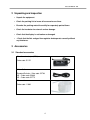
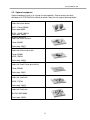
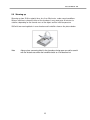
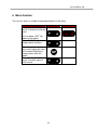
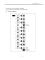
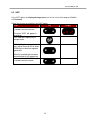
K-SYSTEMS
Instruction Manual
CO² Bench Top Incubator G85
1
Instruction Manual - G85
Table of contents
1
GENERAL INFORMATION & SERVICE ...............................................................................................3
2
UNPACKING AND INSPECTION ............................................................................................................4
3
ACCESSORIES ............................................................................................................................................4
3.1
3.2
4
USER MANUAL...........................................................................................................................................6
4.1
4.2
5
5.3
5.4
5.5
5.6
5.7
5.8
5.9
ASSEMBLING THE G85 ..........................................................................................................................7
CONNECTION TO THE MAINS ..................................................................................................................7
5.2.1
Start of apparatus...................................................................................................................7
KEYBOARD FUNCTIONS .........................................................................................................................8
OPERATING THE HEATED COMPARTMENT ..............................................................................................9
TEMPERATURE SETTING AND CONTROL .................................................................................................9
COMBINATION KEYS ..............................................................................................................................9
GAS FLOW SETTING .............................................................................................................................10
5.7.1
Why gassing?........................................................................................................................10
5.7.2
Working gas pressure...........................................................................................................10
5.7.3
Humidifying the gas mixture ................................................................................................11
5.7.4
Purge function ......................................................................................................................13
TEMPERATURE/FLOW ALARM..............................................................................................................14
5.8.1
Temperature alarm...............................................................................................................14
5.8.2
Gas flow alarm .....................................................................................................................14
WARMING UP ......................................................................................................................................15
MENU FUNCTION....................................................................................................................................16
6.1
6.2
6.3
6.4
6.5
6.6
6.7
6.8
6.9
6.10
6.11
7
DEFINITION OF USE ................................................................................................................................6
GENERAL DESCRIPTION .........................................................................................................................6
FEATURES AND OPERATION ................................................................................................................7
5.1
5.2
6
STANDARD ACCESSORIES ......................................................................................................................4
OPTIONAL EQUIPMENT ..........................................................................................................................5
OVERVIEW OF OPTIONS .......................................................................................................................17
UNIT ..................................................................................................................................................18
RS232 .................................................................................................................................................19
TUNE .................................................................................................................................................20
INT.T..................................................................................................................................................21
TI.ST ...................................................................................................................................................21
ST.ST ...................................................................................................................................................22
HEAT .................................................................................................................................................23
A-ST ...................................................................................................................................................24
HOUR ............................................................................................................................................25
REST..............................................................................................................................................26
USER MAINTENANCE ............................................................................................................................27
7.1
7.2
CLEANING ...........................................................................................................................................27
CALIBRATION ......................................................................................................................................27
8
TROUBLE SHOOTING ............................................................................................................................28
9
TECHNICAL DATA..................................................................................................................................29
10
LIMITED WARRANTY............................................................................................................................30
11
LIABILITY .................................................................................................................................................31
12
REPLACEMENT .......................................................................................................................................31
2
Instruction Manual - G85
1 General Information & Service
COPYRIGHT
This manual contains information that is subject to copyright. All rights reserved. This
manual should not be photocopied, otherwise copied or distributed, completely or in part,
without the approval of K-SYSTEMS Kivex Biotec.
Users of K-SYSTEMS Kivex Biotec products should not hesitate to contact us if there are
any unclear points or ambiguities in this manual.
K-SYSTEMS
Kivex Biotec A/S
Klintehøj vænge 3-5
3460 Birkerød
Denmark
Tel.: +45 45 99 56 00
Fax: + 45 45 99 56 19
E-mail: [email protected]
Internet: www.K-SYSTEMS.dk
Issue 2
Changenote No: 422
Service address:
Please contact your local K-SYSTEMS Kivex Biotec distributor for details of your nearest
authorized service agent.
CAUTION If the equipment is used in a manner not specified by this manual, the safety of
the user may be at risk and the equipment may be damaged. Always use the
equipment as outlined in this instruction manual.
3
Instruction Manual - G85
2 Unpacking and inspection
•
Unpack the equipment.
•
Check the packing list to insure all accessories are there.
•
Examine the packing material carefully for separately packed items.
•
Check the incubator for external surface damage.
•
Check that the display is not broken or damaged.
•
• Check that the lids and gas flow regulator knob operate correctly without
any hindrance.
3 Accessories
3.1 Standard accessories
24 volts main adapter (PSU)
Order code: 51122
Mains Cable
Standard Schuko – Oder code: 52768
UK – Order code: 53886
US – Order code: 52773
Silicone tube
Order code: 11066
4
Instruction Manual - G85
3.2 Optional equipment
Optional equipment consists of a range of warming blocks. Please contact your local
distributor or K-SYSTEMS Kivex Biotec for details about the full range of warming blocks.
Warming block B16
Holds two culture dishes
B16F – Falcon 353001
Order code:26059
B16N – NUNC 150318
Order code: 26060
Warming block B24
Holds one center well dish
Falcon 353653
Order code: 26027
Warming block B25
Holds one 60 mm culture dish
Falcon 353002
NUNC 150288
Order code: 26028
Warming block B26
Holds one 4-well Falcon dish with lid
Falcon 353654
Order code: 26031
Warming block B28
Holds one 4-well dish
NUNC 176740
Order code: 26029
Warming block B29
Holds one 5-well dish
MiniTüb 19021/0005
Order code: 26030
5
Instruction Manual - G85
4 User Manual
4.1 Definition of use
The K-SYSTEMS Kivex Biotec G85 CO² Bench Top incubator is designed for keeping
gametes and embryos in a controlled environment.
4.2 General description
The chambers and aluminum warming blocks maintain a preset temperature in the range
ambient to 42° C. The temperature is electronically controlled by a PID controller and can
be read on the displaying increments of 0.1° C.
The G85 features heated lids. The bottom part is made from thick aluminum that gives
ideal temperature distribution. Back part that houses the electronic is made from stainless
steel. Interchangeable aluminum Warming blocks holding a variety of culture dishes are
available.
The G85 features a built in digital flow meter with a possible flow of 0 - 29 liters per hour
and a humidification system.
The G85 has also a purge function enabling a quick CO2 level recovery within the
chambers. The recovery time is 15 seconds with a pressure of 0.5 bar.
Note
The atmosphere in the chambers may be controlled by flushing with a gas mixture.
Use only 5% CO2 in air.
6
Instruction Manual - G85
5 Features and operation
5.1 Assembling the G85
No assembly needed. Just follow directions in section 5.2 and the unit is ready for use.
5.2 Connection to the mains
The mains voltage is automatically regulated to the correct level by the main adapter
(PSU).
Connect the G85 to the mains supply using the enclosed PSU.
For safety reasons the unit has an external PSU which operates at a low voltage.
5.2.1
Start of apparatus
Connect the unit to the PSU and the PSU to the mains wall socket.
To power up the unit, press the heat on button on the keyboard. The display will indicate
the current temperature.
The aluminum dial on the side of the G85 can be turned and the gas flow level is adjusted.
The valve controlling the flow is a precision valve with a short span from closed to open, so
adjust with slow movements. A hint for adjusting is to close it fully and then open it gently.
7
Instruction Manual - G85
5.3 Keyboard functions
Purge
Heat ON/Off
LED Display
Setpoint
Arrow keys UP/DOWN
Alarm
8
Instruction Manual - G85
5.4 Operating the heated compartment
Action
Press heat ON/OFF key to
show the actual
temperature.
Key
5.5 Temperature setting and control
Action
Press setpoint key and
the set temperature is
shown.
Key
Press and hold setpoint
key.
While holding the
setpoint key in, press
either the arrow UP or
arrow DOWN key to
raise or lower the set
temperature.
When the desired
temperature is
reached, let go of the
setpoint key.
Note The setpoint can be adjusted to a reading between ambient and 49.9 ˚C.
5.6 Combination keys
Action
Press alarm and UP key.
Key
Display
The keyboard is locked.
Press alarm and UP key.
The keyboard is
unlocked.
Press Heat ON/OFF and
setpoint key.
Switches between
temperature and time.
9
Instruction Manual - G85
5.7 Gas flow setting
The display can switch between temperature and flow rate.
The flow rate is shown in the display by the integrated digital flow meter in the G85.
Action
Press arrow key either up or
down one time.
Key
Now the flow rate in liter per hour
will be shown.
The flow rate can be adjusted between 0 – 29 l/h.
If the flow becomes larger that 29 l/h the display will indicate “Hi” (see section 5.8).
Action
Press arrow key either up or
down once again to change to
the display of temperature.
5.7.1
Key
Why gassing?
Most of the culture media which are used in assisted reproduction techniques are sensitive
to changes in pH. Culture media must be maintained at a pH about 7.4. This can be
obtained by gassing with atmosphere of 5% or 6% CO2.
5.7.2
Working gas pressure
Working gas pressure (inlet pressure on the G85) must be regulated to 0.5 bar by a
reduction valve. The reduction valve must be a high quality unit of the pressure type that
can be adjusted precisely in the 0-1 bar range.
The flow rate on the G85 must be adjusted to a specific level in accordance with the use of
the unit.
Frequent openings of the lids will require higher flow rates.
Note Any use of flow type regulators or inadequate quality pressure type regulators will
cause the flow on the G85 to be unstable and drift.
Below is listed the full recovery rates for CO2 level in both chambers in minutes.
This can be used as guideline for the use.
Flow (l/h)
*
Time (min) **
10
12
28
2.8
50
0.9
*Flow setting in display of G85.
**Time it will take to recover CO2 level after a chamber has been opened at the above flow
setting.
10
Instruction Manual - G85
If the use necessitates low recovery times, either a constant high flow must be used or
purging the chambers by setting the flow level at a high rate for 2-3 minutes.
A flow of 10 l/h will be sufficient to sustain the CO2 levels in the chambers when the lids
are not opened. The flow rate should at no time be kept under 8 l/h.
A flow rate of 15-20 l/h should be adequate under most conditions without the use of
manual purge.
5.7.3
Humidifying the gas mixture
In order to avoid Gassing with cold and dry Gas, the built in humidifier can be used.
Connect the tubes as show on the picture below.
Warning Always route the gas as shown or permanent damage to the airflow sensors
may occur.
If the humidification system is not used and the gassing is done with dry gas, a silicone
tube U loop must be connected between the outlet and inlet for the humidification bottle.
K-SYSTEMS have experienced a quantity of failures on the flow sensors due to liquid
entering the sensor and damaging it.
The fault is registered by the user getting a “0” reading in the display, when an obvious
flow can be seen as bubbles in the humidification flask.
When adjustment in the flow rate is done on the regulator valve on the side of the G85, no
changes can be seen to the flow reading in the display. It will stay at “0” disregarding the
flow.
11
Instruction Manual - G85
The fault occurs because of under pressure in the gas supply when the G85 is not in use.
If the user shuts off the gas supply only on the bottle or the external regulator an under
pressure will develop. The under pressure will draw back liquid from the humidification
bottle through the gas outlet to bottle tube and into the G85 where it will damage the flow
sensor.
If the user remembers to completely close the regulator valve on the side of the G85 no
such problem will occur.
•
Alternatively the exterior 5% CO2 supply tube should be disconnected from the G85
when the G85 is not in use.
•
The Gas outlet to bottle tube disconnected when the G85 is not in use.
Or:
There is no recommended hardware update at this time, as such an under pressure
cannot be avoided with certain types of gas regulators. We have considered the addition of
a one-way flow valve in the circuit, but test have shown that under unfortunate
circumstances the process can still be triggered.
The only fully safe way to avoid the problem is as described above.
12
Instruction Manual - G85
A notice or warning sticker could be added to the G85:
•
Close regulator valve fully when not in use:
•
The Gas outlet to bottle tube disconnected when the G85 is not in use
Or:
There is no recommended hardware update at this time, as such an under pressure
cannot be avoided with certain types of gas regulators. We have considered the addition of
a one-way flow valve in the circuit, but test have shown that under unfortunate
circumstances the process can still be triggered.
The only fully safe way to avoid the problem is as described above.
A notice or warning sticker could be added to the G85:
•
Close regulator valve fully when not in use:
•
Disconnect gas outlet to bottle tube when not in use.
Or:
If the problem has occurred the gas flow sensor PCB will need to be replaced.
5.7.4
Purge function
The G85 has a purge function enabling to have a fast recovery of the CO2 level within the
chambers. This function is to be used when the lid of the chambers have been opened in
order to place or remove culture dishes. The purge time is 15 seconds.
Action
Press the alarm key to
activate the purge
function.
Key
When activated a “Pu”
indication appears on the
display.
13
Instruction Manual - G85
5.8 Temperature/Flow alarm
The G85 has one alarm which is activated on two events:
•
•
5.8.1
Temperature deviations (high or low)
Gas flow
Temperature alarm
The temperature alarm indicates too high or too low temperature.
The alarm will be activated if the temperature rises or falls more than 0.5° C from the
setpoint.
There will be an acoustic signal and the red LED light in the alarm key will be activated.
Action
Press setpoint key and alarm key to mute
the acoustic signal.
Key
Press setpoint key and alarm key once
again to bring the signal back on.
Note The red LED and the acoustic signal will turn off if the temperature or gas flow
stabilizes again to the setpoint level.
5.8.2
Gas flow alarm
The gas flow alarm will get activated, if the flow is higher than 29 l/h.
The display will then show “hi”.
The alarm will also be activated if the flow is “on”, and the heat “off”.
In this case the display will show “f.on”.
Note The maximum flow is 29 l/h. The G85 will not be damaged by a higher flow as
long as the gas flow is kept below 100 l/h.
14
Instruction Manual - G85
5.9 Warming up
Warming up from 20.0 to setpoint takes less than 30 minutes, under normal conditions.
When a cold item is placed in either of the chambers it may need up to 40 minutes to
stabilize, depending on the thermal mass of the object and the initial temperature.
G85 with two warming blocks in one chamber and humidifier show on the picture below.
Note
Always place a warming block in the chambers during warm up and be careful
with the heated area under the humidifier bottle as it will become hot.
15
Instruction Manual - G85
6 Menu function
The user can access a number of advanced functions via the menu.
Action
Press and hold UP+DOWN
key for 3 seconds to enter the
menu.
Key
The first option “UNIT” will
appear in the display.
Press UP/DOWN key to
navigate within the Menu.
While holding the setpoint
key in, press either the arrow
UP or arrow DOWN key to
change values within the
options.
Press and hold UP+DOWN
key for 3 seconds again to
exit the menu.
16
Display
Instruction Manual - G85
The menu consists of the 10 options listed below.
For further detail see the description on the following pages.
6.1 Overview of options
17
Instruction Manual - G85
6.2 UNIT
In the UNIT option the displayed temperature unit can be set to either degrees Celsius
or Fahrenheit.
Follow these steps to navigate in the UNIT option.
Action
Key
Press and hold UP+DOWN key for
3 seconds to enter the menu.
The menu "UNIT" will appear in
the display.
Press and hold setpoint key to
change values.
While holding the setpoint key in,
press either the arrow UP or arrow
DOWN key to select the required
type of unit.
When the required type has been
selected let go of the setpoint key.
Press and hold UP+DOWN key for
3 seconds to exit the menu.
18
Display
Instruction Manual - G85
6.3 RS232
The RS232 option is for serial communication and data logging of the temperature and
alarm conditions.
Follow these steps to navigate in the RS232 option.
Action
Key
Press and hold UP+DOWN key for
3 seconds to enter the menu.
The option "UNIT" will appear in
the display.
Press DOWN key until the option
“RS232” appears in the display.
Press and hold setpoint key to
change values.
While holding the setpoint key in,
press either the arrow UP or arrow
DOWN key to select between
"ON" and "OFF".
“OFF”: The RS232 function is
turned off.
“ON”: Data is send once every two
seconds.
When the required setting is
activated, let go of the setpoint
key.
Press and hold UP+DOWN key for
3 seconds to exit the menu.
Data logging the temperature valves during use
Note
The use of this function warrants extra equipment software.
The parameters on or off will not affect
normal usage when serial communication is not connected.
19
Display
Instruction Manual - G85
6.4 TUNE
The TUNE option is for calibration of the displayed temperature.
If there is an offset between the value on the display and any measurements made with a
high precision external temperature sensor, this can be corrected.
The new temperature reading will be kept as the displayed value, with temperature control
conducted on this basis.
Follow these steps to navigate in the TUNE option.
Action
Key
Press and hold UP+DOWN key for
3 seconds to enter the menu.
The menu "USER" will appear in
the display.
Press DOWN key until the option
“TUNE” appears in the display.
Display
Press and hold setpoint key to
change values.
While holding the setpoint key in,
press either the arrow UP or arrow
DOWN key to select the value
temperature.
When the required setting is
activated, let go of the setpoint
key.
Press and hold UP+DOWN key for
3 seconds to exit the menu.
Any change in the factory set calibration should always be based on very
certain temperature measurements. K-SYSTEMS Kivex Biotec only recommend the
use of a high quality PT-100 sensor that is calibrated with the precision instrument
used for measuring according to the manufacturers specifications. Also ensure an
optimal contact between the sensor and the place measured. Use only a sensor type
that is correct for the purpose and of correct size. If in doubt contact your local
distributor or K-SYSTEMS Kivex Biotec.
20
Instruction Manual - G85
6.5 INT.T
The INT.T (Integral Time) option is for changing the base value for the PID controller.
This should not be attempted by unauthorized persons. If set at a different level the
controlling principle will be affected.
From the factory it is set to a closely calculated value specific for the model.
CAUTION Do not change the value here. If by mistake any changes are made or doubts
occur if the value are correct please set the REST function in the menu for the
restore of the defaults.
6.6 TI.St
The Ti.St (Time Set) option is for setting the time.
Follow these steps to navigate in the Ti.St option.
Action
Key
Press and hold UP+DOWN key for
3 seconds to enter the menu.
The option “UNIT” will appear in
the display.
Press DOWN key until the option
"Ti.St." appears in the display.
Press and hold setpoint key to
change values.
While holding the setpoint key in,
press either the arrow UP to
change minutes or arrow DOWN
key to change the hour.
Press and hold UP+DOWN key for
3 seconds to exit the menu.
21
Display
Instruction Manual - G85
6.7 St.St
The St.St (Start Set) option is the timer function for the heat.
By using this option, time can be saved as the G85 can be ready for use before
procedures start in the morning.
Note
This function will only work correctly if the clock is set.
Follow these steps to navigate in the St.St option.
Action
Key
Press and hold UP+DOWN key for
3 seconds to enter the menu.
The menu "UNIT" will appear in
the display.
Press key DOWN until the option
"St.St" appears in the display.
Display
Press and hold setpoint key to
change values.
While holding the setpoint key,
press either the arrow UP to
change minutes or arrow DOWN
key to change the hour.
When the time is set, let go of the
setpoint
Press and hold UP+DOWN key for
3 seconds to exit the menu.
Note
If the function Heat is set, a dot will light up in the right side of display.
St.St is connected with HEAT. It must be chosen when the timer starts. To turn the heater
on, please see section 6.8.
WARNING Always make sure when the timer function is being used, that the heated area
is clear of any objects that might be damaged by the heat or adversely
affected by it in way.
Caution should always be exercised when a heated area is turned on without
any supervison.
22
Instruction Manual - G85
6.8 HEAT
The HEAT option is used for the heater to turn on at a certain time.
Note
This function only works in conjunction with St.St.
If St.St is set to 8.00 and heat function is on, the heater will
automatically turn on at 8.00 using 24 hour clock.
Follow these steps to navigate in the HEAT menu.
Action
Key
Press and hold UP+DOWN key for
3 seconds to enter the menu.
The first menu "UNIT" will appear
in the display.
Press DOWN key once and the
menu "HEAT" appears in the
display.
Press and hold setpoint key to
change values.
Display
While holding the setpoint key in,
press either arrow UP or arrow
DOWN key to select between
“ON” and “OFF”.
When the required setting is
activated, let go of the setpoint
key.
Press and hold UP+DOWN key for
3 seconds to exit the menu.
Note
A dot will turn on in the right side of display, indicating that the Heat function
is active.
23
Instruction Manual - G85
6.9 A-ST
The A-St (Automatic Start) option is used to repeat the timer (St.St) function every day of
the week.
Note
This function works in conjunction with St.St and HEAT.
If St.St.is set to 8.00 and heat function is on, the heater will automatically turn on at
8.00 every day.
Follow these steps to navigate in the A-st option.
Action
Key
Press and hold UP+DOWN key for
3 seconds to enter the menu.
Display
The option “UNIT” will appear in
the display.
Press DOWN key until the option
“A-st” appears in the display.
Press and hold setpoint key to
change values.
While holding the setpoint key in,
press either arrow UP or arrow
DOWN key to select between
“ON” and “OFF”.
When the required setting is
activated, let go of the setpoint
key.
Press and hold UP+DOWN key for
3 seconds to exit the menu.
Note
If this function is set to ‘on’ the heat function will be repeated every day, but if
A-St function is set to ”off” the heat function will only be activated one time.
24
Instruction Manual - G85
6.10 HOUR
The HOUR option gives the opportunity to show the time on the display when the heat is
off.
Follow these steps to navigate in the HOUR option.
Action
Key
Press and hold UP+DOWN key for
3 seconds to enter the menu.
Display
The option “UNIT will appear in the
display.
Press DOWN key until the option
"HOUR" appears in the display.
Press and hold setpoint key to
change values.
While holding the setpoint key in,
press the arrow UP or arrow
DOWN key to select between
“ON” and “OFF”.
When the required setting is
activated, let go of the setpoint
key.
Press and hold UP+DOWN key for
3 seconds to exit the menu.
If you want to see the time on the display when the heat is turned on.
Follow these steps to switch between time and temperature.
Action
Press and hold setpoint key.
Key
While holding the setpoint key in,
press the HEAT key one time,
then let go of the setpoint key.
The display now shows the time.
25
Display
Instruction Manual - G85
To change back to temperature.
Action
Press and hold setpoint key.
Key
Display
Press the HEAT key one time,
then let go of the setpoint key.
The display now shows the
temperature.
Note
The time is shown as a 24 hour clock e.g 19.30 not 7.30 PM.
6.11 REST
The REST function will restore all factory set values.
Any changes made to the displayed temperature, unit readings and controller value will be
reset.
Note
Calibration value in the TUNE option will remain and not be reset.
Follow these steps to navigate in the REST option.
Action
Key
Press and hold UP+DOWN key for
3 seconds to enter the menu.
The option “UNIT” will appear in
the display.
Press DOWN key until the option
“REST” appears in the display.
Press and hold the setpoint key to
change values.
While holding the setpoint key in,
press either the arrow UP or arrow
DOWN key.
When the display shows “-----“, *let
go of the setpoint key.
Press and hold UP+DOWN key for
3 seconds to exit the menu.
*This means all factory values have now been restored.
26
Display
Instruction Manual - G85
7 User maintenance
7.1 Cleaning
The G85 is a low maintenance unit designed to be both easy to use and clean, plus it is
durable due to its construction.
All surfaces should be cleaned with an 70% alcohol solution on a clean cloth or lint-free
paper towel.
•
Clean all surface components by wiping gently with gauze.
•
To remove fingerprints or oil smudges, wipe with gauze slightly moistened with a
mixture of ether (70%) and alcohol (30%).
Note
Since solvents such as ether and alcohol are highly flammable, they must be
handled carefully. Be sure to keep these chemicals away from open flames or
potential sources of ignition – electrical equipment must be switched off.
Also remember to always use these chemicals only in a well ventilated room.
•
If smudges are difficult to clean, wipe them with a soft cloth slightly moistened with
a diluted neutral detergent.
•
The heated area is able to withstand some water spills. However, precautions are
still necessary if water is spilled on the surface. Unplug the power cord, and then
wipe dry with a dry cloth immediately.
Note
•
If water gets inside the unit, contact your K-SYSTEMS Kivex Biotec
representative to check electrical safety.
Humidification bottle can be put in an autoclave.
7.2 Calibration
For optimal performance the unit should be calibrated once a year by authorized KSYSTEMS Service provider.
27
Instruction Manual - G85
8 Trouble shooting
Symptom
Temperature alarm
is on.
Cause
Temperature more
than ±0.5° C from
set temperature.
No heating.
Setpoint below
ambient.
No mains supply.
Display remains off
when “HEAT” key is
activated.
Flow alarm is on
slow acoustic signal
sounds and the
display shows “-hi-“.
Flow alarm is on.
Fast acoustic signal
sounds and display
shows “f.on“.
Power connector,
not connected.
Defective “HEAT”
key.
The flow is higher
then 29 l/h.
The flow is on and
the heat is off
28
Action
Check the set
temperature. Wait
for the temperature
to stabilize.
Change setpoint
(eg. 37° C).
Plug in the power
connector.
Reconnect power
connector.
Replace the
keyboard.
Reduce the flow.
Turn the flow off.
Instruction Manual - G85
9 Technical data
Material
Weight (without PSU and BLOCK)
Overall dimentions (WxDxH)
Temperature range
Spot temperature accuracy
Flow range
Power consumption
Heating
Gas consumption
Gas inlet pressure
PSU
Alarms
Stainless steel (upper parts)
Aluminium (lower parts)
5.4 kg
267x340x95 mm
Ambient to 42° C
± 0.2° C
0 – 29 litres/hour
120 W
100 W
0 – 29 litres/hour
0.3 – 0.5 Bar
AC input 100-240V 50-60Hz 1.6A MAX
DC output 24V/5A
Audible and visible for out of range
temperature and air flow
29
Instruction Manual - G85
10 Limited warranty
K-SYSTEMS Kivex Biotec warrants to the purchasers of all devices and products
manufactured by K-SYSTEMS Kivex Biotec, the product was prepared and tested in
accordance with good manufacturing practices and guidelines and are in compliance to
the CE norms issued by the competent authority.
In the event of product failure under normal use, due to defects in material or
workmanship, within a period of twenty four months from the date of shipment of the
Product and from the point of origin, the product will be repaired, or at K-SYSTEMS Kivex
Biotec option, replaced, at no charge. This limited warranty does not apply to products
subjected to abnormal use or conditions, improper storage, damaged by accident, misuse
or abuse, improper line voltage, products whose serial number has been altered, to
products not shipped in accordance with the recommendations of K-SYSTEMS Kivex
Biotec, and/or to products altered or serviced by anyone other than K-SYSTEMS Kivex
Biotec authorised distributors. Distributor is responsible for the labour and travel costs
during this period.
This limited warranty is exclusive and in lieu of all other warranties whether written, oral,
expressed or implied. In particular, K-SYSTEMS Kivex Biotec does not warrant that the
product is suitable for the needs of the purchaser and there are no warranties given as to
merchantability or fitness for a particular purpose other than the one specified in KSYSTEMS Kivex Biotec literature that accompanies every specific product. K-SYSTEMS
Kivex Biotec assumes that the Purchaser is experienced in the use of this device and is
able to judge from his/her own expertise the suitability or otherwise of the product for the
intended use.
K-SYSTEMS Kivex Biotec reserves the right to change or discontinue this product without
prior notice.
30
Instruction Manual - G85
11 Liability
Because K-SYSTEMS Kivex Biotec has no control or influence over the conditions under
which this device is used, over its method of use or administration, or on handling of the
product after it leaves its possession, K-SYSTEMS Kivex Biotec takes no responsibility for
the results, use and/or performance of the product. K-SYSTEMS Kivex Biotec expects that
use of the product will be confined to trained and expert users.
In no event shall K-SYSTEMS Kivex Biotec be liable for any direct or indirect damages
including incidental, consequential or special damages, arising out of or in connection with
the use or performance of the product.
If K-SYSTEMS Kivex Biotec provides you with technical documentation, this does not
authorise you to perform repairs, adjustments or alterations on the device or accessories.
No representative of K-SYSTEMS Kivex Biotec and no vendor of the product is authorised
to change any of the foregoing terms and conditions, and the purchaser accepts the
product subject to all terms and conditions herein, subject always to any contrary
provisions which are necessarily implied by stature or law notwithstanding the within terms
and conditions.
12 Replacement
As mentioned in the Limited Warranty, the decision whether to provide any remedy or
whether to refund any portion of the purchase price shall be at the discretion of KSYSTEMS Kivex Biotec.
Before returning a product for any reason, please contact your nearest K-SYSTEMS Kivex
Biotec distributor for assistance and instructions.
Only for all customers in Denmark, Norway and Sweden, please take direct contact with
our head office at:
Tel: +45 4599 5600
Fax: +45 4599 5619
Email: [email protected]
31