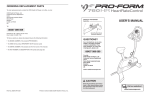
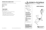
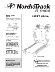
1
ORDERING REPLACEMENT PARTS
To order replacement parts, contact the ICON Health & Fitness, Ltd. office, or write:
ICON Health & Fitness, Ltd.
Customer Service Department
Unit 4, Revie Road Industrial Estate
Revie Road
Beeston
Leeds, LS118JG
UK
Model No. NTEVEL15830
Serial No.
_
USER’S MANUAL
Tel:
08457 089 009
Serial Number
Decal
Outside the UK: 0 (444) 113 387 7133
Fax: 0 (444) 113 387 7125
To help us assist you, please be prepared to give the following information:
• the MODEL NUMBER of the product (NTEVEL15830)
• the NAME of the product (NordicTrack CXT 1200 elliptical exerciser)
®
• the SERIAL NUMBER of the product (see the front cover of this manual)
QUESTIONS?
As a manufacturer, we are committed to providing complete
customer satisfaction. If you
have questions, or if there are
missing parts, please call:
• the KEY NUMBER and DESCRIPTION of the part(s) (see pages 28 to 31)
8457 089 009
Or write:
ICON Health & Fitness, Ltd.
Customer Service Department
Unit 4
Revie Road Industrial Estate
Revie Road
Beeston
Leeds, LS118JG
UK
e-mail: [email protected]
CAUTION
Read all precautions and instructions in this manual before using
this equipment. Keep this manual
for future reference.
Part No. 202616 R1103A
Printed in China © 2003 ICON Health & Fitness, Inc.
Class H Fitness Product
117
46
104
87
84
44 41
84
92
87
113
51
66
111
46
84
9
104
87
67
87 84
46
8
112
67
67
65
29 28
29
76
126
110
76
48
31
4
29
110
30
28
14
76
50
64
49
12
NordicTrack is a registered trademark of ICON Health & Fitness, Inc.
2
46
6
7
42
51
35
82
83
29
47
65
13
47
99
3
10
88 71
90 62
61
37
60
36
47
99
47
48 76
64
76
72
73
109
109
73
70
34
35 101
90
62
72
95
127
93
88
61
103
89
45
59
60
93 63 75
92
43
38
44
63
91
98
55
100
53
98 54
1
95
58
27
76
78
78
77 79
52
79
95
77
74
57
56
83
32
88
90
40
98
98
102 82
80
33
5 81
126
94
51
65 29
110
28
110
30
11
IMPORTANT PRECAUTIONS . . . . . . . . . . . . . . . . . . . . . . . . . . . . . . . . . . . . . . . . . . . . . . . . . . . . . . . . . . . . . .3
BEFORE YOU BEGIN . . . . . . . . . . . . . . . . . . . . . . . . . . . . . . . . . . . . . . . . . . . . . . . . . . . . . . . . . . . . . . . . . . .4
ASSEMBLY . . . . . . . . . . . . . . . . . . . . . . . . . . . . . . . . . . . . . . . . . . . . . . . . . . . . . . . . . . . . . . . . . . . . . . . . . . .5
HOW TO USE THE CHEST PULSE SENSOR . . . . . . . . . . . . . . . . . . . . . . . . . . . . . . . . . . . . . . . . . . . . . . . . .9
HOW TO USE THE ELLIPTICAL EXERCISER . . . . . . . . . . . . . . . . . . . . . . . . . . . . . . . . . . . . . . . . . . . . . . . .11
MAINTENANCE AND TROUBLESHOOTING . . . . . . . . . . . . . . . . . . . . . . . . . . . . . . . . . . . . . . . . . . . . . . . . .26
CONDITIONING GUIDELINES . . . . . . . . . . . . . . . . . . . . . . . . . . . . . . . . . . . . . . . . . . . . . . . . . . . . . . . . . . . .27
PART LIST . . . . . . . . . . . . . . . . . . . . . . . . . . . . . . . . . . . . . . . . . . . . . . . . . . . . . . . . . . . . . . . . . . . . . . . . . . .28
EXPLODED DRAWING . . . . . . . . . . . . . . . . . . . . . . . . . . . . . . . . . . . . . . . . . . . . . . . . . . . . . . . . . . . . . . . . . .30
HOW TO ORDER REPLACEMENT PARTS . . . . . . . . . . . . . . . . . . . . . . . . . . . . . . . . . . . . . . . . . . .Back Cover
94
39
51
111
66
29
28
65
29
TABLE OF CONTENTS
69
108
69
69
16
107
106
17
R1103A
IMPORTANT PRECAUTIONS
WARNING: To reduce the risk of serious injury, read the following important precautions before using the elliptical exerciser.
11. If you feel pain or dizziness whilst exercising, stop immediately and cool down.
2. It is the responsibility of the owner to ensure
that all users of the elliptical exerciser are
adequately informed of all precautions.
12. The pulse sensors are not medical devices.
Various factors, including the user's movement, may affect the accuracy of heart rate
readings. The pulse sensors are intended
only as exercise aids in determining heart
rate trends in general.
15
69
69
18
116
98
98
21
98
98
124
119
123
97
22
98
26
8. Wear appropriate exercise clothing when
using the elliptical exerciser. Always wear
athletic shoes for foot protection.
9. Always hold the handlebars when mounting,
dismounting, or using the elliptical exerciser.
10. Keep your back straight when using the
elliptical exerciser; do not arch your back.
WARNING:
Before beginning this or any exercise program, consult your physician.
This is especially important for persons over the age of 35 or persons with pre-existing health problems. Read all instructions before using. ICON assumes no responsibility for personal injury or
property damage sustained by or through the use of this product.
86
110
68
26
118
123
120
124
119
123
86
31
105
24
122
15. The decal shown below has been placed on
the elliptical exerciser in the locations
shown on page 4. If the decal is missing or
illegible, please call our Customer Service
Department at 08457 089 009 to order a free
replacement decal. Apply the decal in the
locations shown.
7. The elliptical exerciser should not be used by
persons weighing more than 115 kg (250 lbs).
2
86
96
85
25
14. Always unplug the power cord immediately
after use and before cleaning the elliptical
exerciser.
6. Keep children under age 12 and pets away
from the elliptical exerciser at all times.
98
110
26
98
85
13. When you stop exercising, allow the pedals
to slowly come to a complete stop. The elliptical exerciser does not have a free wheel;
the pedals will continue to move until the
flywheel stops.
5. Inspect and properly tighten all parts regularly. Replace any worn parts immediately.
118
120
123
68
108
69 108
125
26
86
23
105
122
115
EXPLODED DRAWING—Model No. NTEVEL15830
3. The elliptical exerciser is intended for
in-home use only. Do not use the elliptical
exerciser in a commercial, rental, or institutional setting.
4. Place the elliptical exerciser on a level surface, with a mat beneath it to protect the
floor or carpet. Keep the elliptical exerciser
indoors, away from moisture and dust.
19
121
69
114
69
20
98
69
1. Read all instructions in this manual before
using the elliptical exerciser.
30
3
Key No. Qty.
BEFORE YOU BEGIN
Congratulations for selecting the new NordicTrack
CXT 1200 elliptical exerciser. The CXT 1200 is an
incredibly smooth exerciser that moves your feet in a
natural elliptical path, minimising the impact on your
knees and ankles. And the unique CXT 1200 features
adjustable resistance and incline to help you get the
most from your exercise. Welcome to a whole new
world of natural, elliptical-motion exercise.
tions after reading this manual, please call our
Customer Service Department at 08457 089 009. To
help us assist you, please note the product model
number and serial number before calling. The model
number is NTEVEL15830. The serial number can be
found on a decal attached to the elliptical exerciser
(see the front cover of this manual for the location of
the decal).
For your benefit, read this manual carefully before
you use the elliptical exerciser. If you have ques-
Before reading further, please familiarise yourself with
the parts that are labelled in the drawing below.
®
107
108
109
110
111
112
113
114
115
116
117
118
2
3
2
6
2
2
1
1
1
1
1
2
Description
Key No. Qty.
Lower Foam Grip
M4 x 25mm Tek Screw
7.6mm Spacer
Wheel Bushing
M8 x 19mm Patch Screw
Wheel
Belt
Pulse Extension Wire
Upper Wire Harness
Power Cord
Power Socket
Upper Body Arm
119
120
121
122
123
124
125
126
127
#
#
2
2
2
2
4
2
1
2
2
Description
Weld Spacer
Sleeve
Upper Body Foam Grip
Upper Body Endcap
Upper Body Bushing
M5 x 4mm Screw
Right Upper Body Leg
M10 Washer
Ramp Guard
Hex Key
User’s Manual
Note: # indicates a non-illustrated part. Specifications are subject to change without notice. See the back cover
of this manual for information about ordering replacement parts.
Fan
Water Bottle Holder*
Bookrack
Console
Handlebar
Upper Body Arm
Pulse Sensor
Upright
FRONT
Warning Decal
(One on each side)
Ramp
Warning Decal
Wheel
BACK
Pedal
Pedal Leg
Power Socket
RIGHT SIDE
Levelling Foot
4
*No water bottle is included
29
PART LIST—Model No. NTEVEL15830
Key No. Qty.
1
2
3
4
5
6
7
8
9
10
11
12
13
14
15
16
17
18
19
20
21
22
23
24
25
26
27
28
29
30
31
32
33
34
35
36
37
38
39
40
41
42
43
44
45
46
47
48
49
50
51
52
53
1
1
1
1
1
1
1
1
1
1
1
1
1
1
1
1
1
1
1
2
1
1
1
1
1
2
1
4
8
2
1
1
1
1
2
1
1
1
1
1
1
1
1
2
1
4
4
2
1
1
4
1
1
Description
Key No. Qty.
Frame
Upright
Ramp
Left Pedal Leg
Right Pedal Leg
Rear Stabiliser
Rear Stabiliser Cover
Front Stabiliser
Front Stabiliser Cover
Left Pedal
Right Pedal
Incline Motor
Incline Axle
Pivot Axle
Left Side Shield
Right Side Shield
Console
Right Flywheel Cover
Left Flywheel Cover
Pulse Sensor w/Wire
Right Incline Cover
Left Incline Cover
Right Handlebar
Left Handlebar
Upper Handlebar Cover
Handlebar Cover
Frame Cover
Pedal Wheel
Wheel Bearing
Wheel Frame
Left Upper Body Leg
“C” Magnet
Magnet Bracket
Left Crank Arm
28.7mm Pulley Spacer
Flywheel
Magnet
Pulley
Control Box Cover
Control Board
Control Box
Lower Wire Harness
Crank
Crank Bearing
Idler
Foot
Ramp Bushing
Ramp Cover
Incline Sensor
Sensor Cover
Pedal Leg Bushing
Resistance Motor
Reed Switch Bracket
54
55
56
57
58
59
60
61
62
63
64
65
66
67
68
69
70
71
72
73
74
75
76
77
78
79
80
81
82
83
84
85
86
87
88
89
90
91
92
93
94
95
96
97
98
99
100
101
102
103
104
105
106
28
1
1
1
1
1
1
2
2
2
2
2
2
2
2
2
10
2
1
1
2
1
1
8
4
4
4
2
1
2
4
8
4
6
8
3
1
3
2
2
2
3
6
1
2
15
2
4
2
1
1
2
2
2
R1103A
Description
Clamp
Reed Switch/Wire
Return Spring
Guide Rod
Resistance Cable
Flywheel Axle
Flywheel Bearing
Eye Bolt
Adjustment Bracket
M8 x 47mm Button Screw
M6 Washer
M10 x 78mm Bolt Set
M8 Washer
M10 x 50mm Bolt Set
Handlebar Bushing
M4 x 16mm Tek Screw
M10 x 108mm Button Screw
M8 Tek Washer
M11 x 40mm Bolt Set
M10 Split Washer
M8 x 25mm Button Bolt
M10 x 19mm Button Bolt
M6 x 16mm Patch Screw
M5 Nut
M5 x 16mm Bolt
M5 Washer
M6 x 18mm Bolt
M6 x 25mm Bolt
5/16” x 25mm Flange Screw
M8 x 58mm Button Screw
M8 x 44mm Button Screw
M8 x 41mm Button Bolt
M8 Jam Nut
M4 x 38mm Screw
M8 Nylon Locknut
M10 Nylon Locknut
M6 Nut
M6 Nylon Locknut
Snap Ring
M8 x 54mm Button Screw
M4 x 10mm Screw
M4 x 19mm Screw
M4 x 12mm Round Head Screw
M4 x 25mm Screw
M4 x 16mm Screw
Ramp Spacer
M5 Nylon Locknut
31.5mm Pulley Spacer
Right Crank Arm
Flywheel Spacer
Support Plate
M8 x 38mm Button Bolt
Upper Foam Grip
ASSEMBLY
Assembly requires two persons. Place all parts of the elliptical exerciser in a cleared area and remove the
packing materials. Do not dispose of the packing materials until assembly is completed. In addition to the
included hex keys, assembly requires a phillips screwdriver
, two adjustable
spanners
, a rubber mallet
, and pliers
.
As you assemble the elliptical exerciser, use the drawings below to identify the small parts used in assembly.
The number in parenthesis below each drawing refers to the key number of the part, from the PART LIST on
pages 28 and 29. The second number refers to the quantity used in assembly. Note: Some small parts may
have been pre-assembled. If a part is not in the parts bag, check to see if it is pre-assembled.
M6 Washer
(64)–2
M4 x 16mm
Screw (98)–4
M10 Split
Washer (73)–2
M6 x 16mm Patch
Screw (76)–4
7.6mm Spacer
(109)–2
M10 Washer
(126)–2
M8 Jam Nut
(86)–6
M8 x 41mm Button
Bolt (85)–4
M8 x 58mm Button Screw (83)–4
M8 x 44mm Button Screw (84)–8
M4 x 12mm
Round Head
Screw (96)–1
M10 x 78mm Bolt Set (65)–2
M10 x 108mm Button Screw (70)–2
M8 x 38mm Button Bolt
(105)–2
1. Identify the Front Stabiliser (8). Whilst another person
lifts the front of the Frame (1) and holds the Pedal
Legs (4, 5) in the position shown, attach the Front
Stabiliser to the Frame with four M8 x 44mm Button
Screws (84) and a Support Plate (104).
1
1
4, 5
Whilst another person lifts the rear of the Frame
(1), attach the Rear Stabiliser (not shown) to the
Frame in the same way.
8
104
84
5
84
2. Identify the Pivot Axle (14), which is the longer of the
two axles. Slide a Ramp Cover (48) onto an M6 x
16mm Patch Screw (76) as shown. Tighten the Patch
Screw into one end of the Pivot Axle. Apply a small
amount of the included grease to the Pivot Axle.
2
CONDITIONING GUIDELINES
48 76
Tubes
Have a second person hold the two Ramp Spacers
(99) against the sides of the Frame (1) so that they
cover the indicated tubes on the Frame. Align the
round tubes on the Ramp (3) with the Ramp Spacers.
Make sure that the Ramp is turned as shown in
drawing 3 below. Insert the Pivot Axle (14) into the
Ramp, the Ramp Spacers, and the Frame. If necessary, tap the Pivot Axle with a rubber mallet to insert it.
Grease
The pulse sensors are not medical devices.
Various factors, including the user's movement, may affect the accuracy of heart rate
readings. The pulse sensors are intended
only as exercise aids in determining heart
rate trends in general.
99
48
3. Slide an M6 Washer (64) onto an M6 x 16mm Patch
Screw (76). Tighten the Patch Screw into one end of
the Incline Axle (13). Apply a small amount of grease
to the Incline Axle.
14
99
76
Tubes
For maximum fat burning, adjust the intensity of your
exercise until your heart rate is near the middle number in your training zone as you exercise.
Aerobic Exercise
If your goal is to strengthen your cardiovascular system, your exercise must be “aerobic.” Aerobic exercise is activity that requires large amounts of oxygen
for prolonged periods of time. This increases the
demand on the heart to pump blood to the muscles,
and on the lungs to oxygenate the blood. For aerobic
exercise, adjust the intensity of your exercise until
your heart rate is near the highest number in your
training zone as you exercise.
1
The following guidelines will help you to plan your
exercise program. Remember that proper nutrition
and adequate rest are essential for successful results.
3
EXERCISE INTENSITY
Motor
Screw
Raise the Ramp (3). Insert the Incline Axle (13) into
the welded tube under one side of the Ramp, through
the motor screw, and then into the welded tube under
the other side of the Ramp. As you insert the Incline
Axle through the motor screw, make sure that the
motor screw does not turn.
WARNING:
Before beginning this or any exercise program, consult your physician. This is especially important for persons over the age of 35
or persons with pre-existing health problems.
3
Slide the other Ramp Cover (48) onto an M6 x 16mm
Patch Screw (76) as shown. Tighten the Patch Screw
into the open end of the Pivot Axle (14).
During the first few minutes of exercise, your body
uses easily accessible carbohydrate calories for energy. Only after the first few minutes of exercise does
your body begin to use stored fat calories for energy.
If your goal is to burn fat, adjust the intensity of your
exercise until your heart rate is near the lowest number in your training zone as you exercise.
76
64
3
Grease
Slide an M6 Washer (64) onto an M6 x 16mm Patch
Screw (76). Tighten the Patch Screw into the open
end of the Incline Axle (13).
Whether your goal is to burn fat or to strengthen your
cardiovascular system, the key to achieving the
desired results is to exercise with the proper intensity.
The proper intensity level can be found by using your
heart rate as a guide. The chart below shows recommended heart rates for fat burning, maximum fat
burning, and cardiovascular (aerobic) exercise.
WORKOUT GUIDELINES
Each workout should include the following three parts:
A warm-up, consisting of 5 to 10 minutes of stretching
and light exercise. A proper warm-up increases your
body temperature, heart rate, and circulation in preparation for exercise.
13
76 64
4. Have another person hold the Upright (2) in the position shown. Make sure that the Upright is turned as
shown in drawing 5 on page 7.
Connect the Upper Wire Harness (115) to the Lower
Wire Harness (42). Carefully pull the upper end of
the Upper Wire Harness to remove the slack from
the Wire Harnesses. Insert the Upright (2) into the
Frame (1). Be careful to avoid disconnecting or
pinching the Wire Harnesses. Attach the Upright with
two M10 x 108mm Button Screws (70), two M10 Split
Washers (73), and two 7.6mm Spacers (109); make
sure that the curved sides of the Spacers are facing the Upright. Be careful to avoid damaging the
Wire Harnesses with the Button Screws.
Training zone exercise, consisting of 20 to 30 minutes of exercising with your heart rate in your training
zone. (During the first few weeks of your exercise
program, do not keep your heart rate in your training
zone for longer than 20 minutes.)
4
2
73
70
73
109
6
115
109
A cool-down, with 5 to 10 minutes of stretching. This
will increase the flexibility of your muscles and will
help to prevent post-exercise problems.
To find the proper heart rate for you, first find your age
on the bottom line of the chart (ages are rounded off
to the nearest ten years). Next, find the three numbers
above your age. The three numbers are your “training
zone.” The lower two numbers are recommended
heart rates for fat burning; the highest number is the
recommended heart rate for aerobic exercise.
EXERCISE FREQUENCY
To maintain or improve your condition, complete three
workouts each week, with at least one day of rest
between workouts. After a few months of regular exercise, you may complete up to five workouts each week
if desired. The key to success is to make exercise a
regular and enjoyable part of your everyday life.
42
1
Fat Burning
To burn fat effectively, you must exercise at a relatively low intensity level for a sustained period of time.
27
5. Slide a Weld Spacer (119) onto the axle on the left
side of the Upright (2), with the open side of the Weld
Spacer facing the Upright.
MAINTENANCE AND TROUBLESHOOTING
Inspect and properly tighten all parts of the elliptical
exerciser regularly. Replace any worn parts immediately.
HOW TO MOVE THE ELLIPTICAL EXERCISER
Stand in front of the elliptical exerciser, hold the handlebars firmly, and place one foot against the ramp in
the location shown below. Pull the handlebars until
the elliptical exerciser can be moved on the front
wheels, and carefully move the elliptical exerciser to
the desired location. Then, place one foot against the
ramp, and lower the elliptical exerciser. Due to the
size and weight of the elliptical exerciser, use
extreme caution whilst moving and lowering it.
For smooth
operation of the
Wheels
elliptical exerciser, inspect
and clean the
incline ramp
Incline
regularly using
Ramp
a soft cloth and
mild detergent.
Other parts of
the elliptical
exerciser can
also be cleaned in this way. Keep liquids off the
console. Never use abrasives or solvents.
5
23
85
Locate the Upper Body Arm (118) that has the Left
Upper Body Leg (31) inside of it (the Left Upper Body
Leg is marked with a sticker). Hold the Upper Body
Arm with one hand, hold the Left Upper Body Leg with
your other hand, and slide the Upper Body Arm onto
the axle on the left side of the Upright (2). Then, slide
the Left Upper Body Leg out of the Upper Body Arm
until it rests on the Ramp (3).
114
20
24
86
119
118
Have another person hold the Left Handlebar (24)
near the Upright (2) as shown. Connect the left Pulse
Sensor Wire (20) to the Pulse Extension Wire (114).
105
118
Handlebars
PULSE SENSOR TROUBLESHOOTING
If the chest pulse sensor does not function properly,
see CHEST PULSE SENSOR TROUBLESHOOTING
on pages 9 and 10. If the handgrip pulse sensor does
not function properly, see step 5 on page 14.
Place your
foot here
HOW TO CALIBRATE THE INCLINE RAMP
2
Slide the upper end of the Left Handlebar (24) into the
tube on the front of the Upright (2), whilst sliding the
lower end of the Left Handlebar onto the axle on the
left side of the Upright. Attach the upper end of the
Left Handlebar with two M8 x 41mm Button Bolts (85)
and two M8 Jam Nuts (86); be careful not to damage
the Wires (20, 114) as you insert the Button Bolts.
Make sure that the Jam Nuts are resting in the
hexagonal holes in the Left Handlebar. Attach the
lower end of the Left Handlebar with an M8 x 38mm
Button Bolt (105) and an M8 Jam Nut (86).
86
31
3
Attach the other Upper Body Arm (118) and the Right
Handlebar (23) to the Upright (2) in the same way.
Wheel
If the elliptical exerciser’s incline ramp does not function properly, activate the calibration process by following the steps below.
1. Hold down the Resistance 1 button and the
Program Select button simultaneously for about
five seconds. Note: If numbers appear in the main
display, disregard the numbers.
HOW TO LEVEL THE ELLIPTICAL EXERCISER
If the elliptical
exerciser rocks
during use, turn
one or both of
the Levelling feet
under the rear
Stabiliser until
the rocking
motion is eliminated.
2. Press the Program Select button again. Note: A
combination of letters and numbers may appear in
the main display.
3. Press the 10° or 30° Ramp button. The ramp will
move all of the way up and then all of the way
down.
4. Press the Program Select button three times. The
console will then be in the normal operating mode
and the elliptical exerciser will be ready for use.
6. Look inside one of the Handlebar Covers (26) and
locate the square tabs connecting the two halves.
Gently lift the tabs and disconnect the halves.
6
25
Hold the two halves of the Handlebar Cover (26)
around the tube on the left side of the Upright (2). Align
the halves and press them together until they lock.
Levelling
Foot
Attach the other Handlebar Cover (26) to the right side
of the Upright (2) in the same way.
Hold the halves of the Upper Handlebar Cover (25)
around the tube on the front of the Upright (2); be
careful not to damage the Wires (not shown).
Attach the Upper Handlebar Cover with an M4 x 12mm
Round Head Screw (96).
25
2
96
26
26
26
26
7
7. Identify the Left Pedal (10), which is widest at the rear
and has an opening on the left side. Attach the Left
Pedal to the Left Pedal Leg (4) with two M8 x 58mm
Button Screws (83).
7
1
5
2
11
Attach two Pedal Wheels (28), an M10 Washer (126),
and the Left Upper Body Leg (31) to the Wheel Frame
(30) on the Left Pedal Leg (4) with an M10 x 78mm
Bolt Set (65). Make sure that the Bolt Set, Pedal
Wheels, Washer, and Upper Body Leg are oriented
as shown.
31
Wide
End
65
126
3
28
28
Press the Progress button.
When the Progress button is pressed, the words
“TO CHART YOUR PROGRESS USE UP/DOWN
ARROWS TO SCROLL AND ‘ENTER’ TO
SELECT” will scroll across the main display.
30
Attach the other two Pedal Wheels, the Right Upper
Body Leg, and an M10 Washer (not shown) to the
Wheel Frame (not shown) on the Right Pedal Leg (5)
in the same way.
If you selected a weight loss chart, the matrix
will display a chart that shows your latest ten
body weight measurements compared
to your body weight
goal. The bottom of
the chart represents
your body weight
goal; when only one
indicator is lit in a column, you have reached your goal. The chart
above, for example, shows that the user’s body
weight has decreased and that she has reached
her goal.
Enter your user number.
See step 3 on page 23.
10
65
4
4
8
Do not pinch
the wires
during this step.
Connect the Upper Wire Harness (115) to the wire harness on the Console (17). Connect the Pulse
Extension Wire (114) to the pulse wire on the Console.
Next, locate the two ground wires that are attached
with a screw to the Upright (2). Connect the ground
wires to the two smallest wires on the Console.
17
5
114
115
Ground
Wires
98
6
2
9
117
116
The main display will show the latest body weight
that you have entered, your body weight goal,
and the number of times that you should exercise
per week. Note: If you have not entered your
body weight (see step 6 on page 23), the console
will automatically assign a body weight of 68 kgs
(150 lbs.). If you have not entered a body weight
goal (see step 5 on page 24), the console will
automatically assign a goal of 63 kgs (140 lbs.).
Select a fat burn chart or a weight loss chart.
For the console to display a chart showing your
fat burning progress, press the Enter button. For
the console to display a chart showing your
weight loss progress, press the Up Arrow button
and then press the Enter button.
98
Carefully insert all excess wiring up into the Console
(17) and down into the Upright (2). Attach the Console
to the Upright with four M4 x 16mm Screws (98).
(Note: The Screws may be shipped in the console
box.) Be careful to avoid pinching the wires.
Change your personal data if desired.
If there has been a change in any of the personal
data that you have entered, such as your weight,
press the Measure button whilst the words “IF
YOU WISH TO CHANGE USER INFO PRESS
‘MEASURE’ NOW” appear in the main display.
Then, make the necessary changes. (See HOW
TO MEASURE YOUR BODY FAT PERCENTAGE
on page 23.)
83
9. Plug the Power Cord (116) into the Power Socket
(117) at the rear of the elliptical exerciser.
Begin pedalling to activate the console.
See step 1 on page 13.
Attach the Right Pedal (11) to the Right Pedal Leg (5)
in the same way.
8. Have another person hold the Console (17) near the
Upright (2).
The main display will show the latest measurement of your body fat percentage, your body fat
goal, and the number of times that you should
exercise per week. Note: If you have not measured your body fat percentage (see page 23),
the console will automatically assign a body fat
percentage of 0%. If you have not entered a body
fat goal (see step 5 on page 24), the console will
automatically assign a goal of 20% body fat.
HOW TO CHART YOUR PROGRESS
118
7
View your progress chart in the matrix.
After you have viewed the chart, the words
“GRAPH RESET YES/NO” will appear in the
main display. To delete your last ten body fat or
body weight measurements, press the Up Arrow
(yes) button. If you do not wish to reset the chart,
press the Down Arrow (no) button.
If you selected a fat burn chart, the matrix will
display a chart that shows your latest ten body
fat measurements
compared to your
body fat goal. The
bottom of the chart
represents your
body fat goal; when
only one indicator
is lit in a column,
you have reached your goal. The chart above, for
example, shows that the user’s body fat percentage is decreasing but that he has not yet
reached his goal.
If you wish to measure your body fat percentage, see
HOW TO MEASURE YOUR BODY FAT PERCENTAGE on page 23.
If you wish to receive a custom workout based on the
personal data you have entered, see HOW TO USE A
CUSTOM PROGRAM on page 24.
10.Make sure that all parts of the elliptical exerciser are properly tightened. Cover the floor beneath the
elliptical exerciser to protect the floor from damage. Note: Some extra hardware may be left over.
8
Reset the chart if desired.
25
5
HOW TO USE A CUSTOM PROGRAM
If you selected a Fat Burn program, the main
display will show a body fat goal. If you have
already entered a body fat goal, press the Enter
button. To change the body fat goal, press the Up
Arrow or Down Arrow button, and then press the
Enter button. Note: The body fat goal must be at
least 5%.
In addition to offering personal trainer programs, the
console can provide custom fat burn, weight loss, or
cardio programs based on the personal data that you
have entered. Follow the steps below to use a custom
program.
1
Begin pedalling to activate the console.
If you selected a Weight Loss program, the
main display will show a body weight goal. If you
have already entered a body weight goal, press
the Enter button. To change the body weight
goal, press the Up Arrow or Down Arrow button,
and then press the Enter button.
See step 1 on page 13.
2
Press the Program button.
When the Program button is pressed, the words
“TO RECEIVE A CUSTOM WORKOUT BASED
ON YOUR PERSONAL INFO, USE UP/DOWN
ARROWS TO SCROLL AND ‘ENTER’ TO
SELECT” will scroll across the main display.
3
HOW TO USE THE CHEST PULSE SENSOR
To get the best performance from the chest pulse sensor, please read the instructions below.
6
Select a custom Fat Burn, Weight Loss, or
Cardio program.
The chest pulse sensor consists of two components:
the chest strap and the sensor unit. Follow the steps
below to put on the chest pulse sensor.
7
The custom program will function in the same way
as a personal trainer program. (See step 3 on
page 15.)
If you selected a Weight Loss program, the
main display will show the latest body weight that
you have entered.
When you have completed the program, the
words “END OF PROGRAM” will appear in the
main display.
Sensor Unit
1
2
If you wish to measure your body fat percentage, see
HOW TO MEASURE YOUR BODY FAT PERCENTAGE on page 23.
If you wish to view your progress during recent workouts, see HOW TO CHART YOUR PROGRESS on
page 25.
3
24
• Make sure that the chest pulse sensor is worn
exactly as described in step 2 at the left. If the chest
pulse sensor does not function when positioned as
described, move it slightly lower or higher on your
chest.
Tab
Press the Enter button to start the program.
If you selected a Fat Burn program, the main
display will show the latest measurement of your
body fat percentage.
If there has been a change in any of the personal
data that you have entered, such as your weight,
press the Measure button whilst the words “IF
YOU WISH TO CHANGE USER INFO PRESS
‘MEASURE’ NOW” appear in the main display.
Then, make the necessary changes. (See HOW
TO MEASURE YOUR BODY FAT PERCENTAGE
on page 23.)
If the chest pulse sensor does not function properly, or if the displayed heart rate is excessively high
or low, try the steps below.
Chest Strap
The maximum resistance setting of the custom
program will then appear in the main display.
See step 3 on page 23.
CHEST PULSE SENSOR TROUBLESHOOTING
Select an intensity level for the program.
To select an intensity level for the program, first
press the Up Arrow or Down Arrow button until
the word “EASY,” “MODERATE,” “HARD,” or
“INTENSE” appears in the main display. Then,
press the Enter button.
Enter your user number.
the two electrode areas on the inner side. Using
a saline solution such as saliva or contact lens
solution, wet both electrode areas. Return the
sensor unit to a position against your chest.
HOW TO PUT ON THE CHEST PULSE SENSOR
If you selected a Cardio program, it is not necessary to enter a goal.
To receive a custom Fat Burn program, press the
Enter button. To receive a custom Weight Loss
program or Cardio program, press the Up Arrow
button and then press the Enter button.
4
Enter a goal.
Sensor
Unit
• Each time you use the chest pulse sensor, use
saline solution such as saliva or contact lens solution to wet the two electrode areas on the sensor
unit (see the drawing in step 3 at the left). If heart
rate readings do not appear until you begin perspiring, re-wet the electrode areas.
Buckle
Refer to the inset drawing above. Insert the tab
on one end of the chest strap through one end of
the sensor unit as shown. Then, press the end of
the sensor unit under the buckle on the chest
strap.
• Make sure that you are within arm’s length of the
console. For the console to display heart rate
readings, the user must be within arm’s length of
the console.
Wrap the
chest pulse
Logo
sensor
around
your chest.
Attach the
free end of
the chest
strap to the sensor unit as described above.
Adjust the length of the chest strap, if necessary.
The chest pulse sensor should be under your
clothing, against your skin, and as high under the
pectoral muscles or breasts as is comfortable.
Make sure that the logo is facing forward and is
right-side-up.
Pull the
sensor unit
away from
your body
a few centimeters
and locate
• The chest pulse sensor is designed to work with
people who have normal heart rhythms. Heart rate
reading problems may be caused by medical conditions such as premature ventricular contractions
(pvcs), tachycardia bursts, and arrhythmia.
• The operation of the chest pulse sensor can be
affected by magnetic interference caused by high
power lines or other sources. If it is suspected that
magnetic interference may be causing a problem,
try relocating your exercise equipment.
• If the chest pulse sensor still does not function properly, test the chest pulse sensor in the following way:
Hold the chest
pulse sensor
and place your
thumbs over
the electrode
areas as
shown.
Electrode Areas
9
Electrode Areas
Next, hold the chest pulse sensor near the console.
Whilst holding one thumb stationary, begin tapping
the other thumb against the electrode area at a rate
of about one tap per second. Check the heart rate
reading on the console.
CHEST PULSE SENSOR CARE
• Thoroughly dry the chest pulse sensor after each
use. The chest pulse sensor is activated when the
electrode areas are wetted and the chest pulse sensor is put on; the chest pulse sensor shuts off when
it is removed and the electrode areas are dried. If
the chest pulse sensor is not dried after each use, it
may remain activated longer than necessary, draining the battery prematurely.
• If the chest pulse sensor does not function properly
after you have followed all of the above instructions,
the battery should be replaced in the following way:
Locate the battery
cover on the back of
the sensor unit. Insert
a coin into the slot in
the cover, turn the
cover counterclockwise, and remove the
cover.
Remove the old battery and insert a
new CR 2032 battery. Make sure that
the battery is
turned so the writing is on top.
Replace the battery
cover and turn it
clockwise to close it.
• Store the chest pulse sensor in a warm, dry place.
Do not store the chest pulse sensor in a plastic bag
or other container that may trap moisture.
• Do not expose the chest pulse sensor to direct
sunlight for extended periods of time. Do not expose
the chest pulse sensor to temperatures above 122° F
(50° C) or below 14° F (-10° C).
• Do not excessively bend or stretch the sensor unit
when using or storing the chest pulse sensor.
5
HOW TO MEASURE YOUR BODY FAT
PERCENTAGE
If you have already entered your height, press
the Enter button. If you have not entered your
height, press the Up Arrow or Down Arrow button
to enter your height, and then press the Enter
button.
CAUTION
: The console uses a
bioelectrical impedance analysis method to
determine body fat percentage, sending a
harmless signal through the body. Do not
measure your body fat percentage if you
have an internal medical device such as a
pacemaker. Consult your physician if you
have questions.
6
7
• Clean the sensor unit using a damp cloth—never
use alcohol, abrasives, or chemicals. The chest
strap may be hand washed and air dried.
2
Begin pedalling to activate the console.
Press the Measure button.
8
When the Measure button is pressed, the words
“THIS PROGRAM MEASURES YOUR BODY
FAT PERCENT” and “USE UP/DOWN ARROWS
TO SCROLL AND ‘ENTER’ TO SELECT” will
scroll across the main display.
Note: If you wish to change any of the information that you have entered, press the Left Arrow
or Right Arrow button until the desired information
appears in the main display. Then, change the
information by pressing the Up Arrow, Down
Arrow, and Enter buttons.
Enter your user number.
9
The console can save personal data for three different users. The words “USER 1” will appear in
the main display. To designate yourself as user 1,
press the Enter button. To designate yourself as
user 2 or user 3, press the Up Arrow button until
the words “USER 2” or “USER 3” appear in the
main display. Then, press the Enter button.
4
Hold the handgrip pulse sensor.
When you hold the handgrip pulse sensor, the
main display will begin a 10-second countdown.
When the countdown ends, your body fat percentage will appear in the main display. The console may also display the words, “RECOMMENDED BODY FAT PERCENT SHOULD BE
LESS THAN 30 FOR WOMEN AND LESS THAN
20 FOR MEN.”
Enter your age.
If you have already entered your age, simply
press the Enter button. If you have not entered
your age, press the Up Arrow or Down Arrow button to enter your age, and then press the Enter
button.
10
Enter the number of times that you exercise
per week.
If you have already entered the number of times
that you exercise per week, press the Enter button. If you have not entered the number, press
the Up Arrow or Down Arrow button to enter the
number, and then press the Enter button.
Before the console measures your body fat percentage, it will prompt you to enter personal data
such as your age and weight. Use the Up Arrow,
Down Arrow, and Enter buttons to enter information. Note: The information that appears in the
main display will flash until it is modified.
3
Enter your gender.
If you have already entered your gender (“F” for
female or “M” for male), press the Enter button. If
you have not entered your gender, press the Up
Arrow or Down Arrow button, and then press the
Enter button.
See step 1 on page 13.
CR 2032
Battery
Enter your weight.
If you have already entered your weight, press
the Enter button. If you have not entered your
weight, press the Up Arrow or Down Arrow button
to enter your weight, and then press the Enter
button.
Follow the steps below to measure your body fat
percentage.
1
Enter your height.
If you wish to receive a custom workout based on the
personal data that you have entered, see HOW TO
USE A CUSTOM PROGRAM on page 24.
If you wish to view your progress during recent workouts, see HOW TO CHART YOUR PROGRESS on
page 25.
23
5
HOW TO USE PROGRAMS DIRECTLY FROM
OUR WEB SITE
Our Web site at www.iFIT.com allows you to play
iFIT.com audio and video programs directly from the
internet. To use programs from our Web site, the elliptical exerciser must be connected to your home computer. See HOW TO CONNECT YOUR COMPUTER
on page 19. In addition, you must have an internet
connection and an internet service provider. A list of
specific system requirements will be found on our Web
site.
6
7
Read and follow the on-line instructions for using
a program.
HOW TO PLUG IN THE POWER CORD
Follow the on-line instructions to start the
program.
Return to the elliptical exerciser and begin
pedalling.
When the on-screen countdown ends, the program will begin. The program will function in
almost the same way as a personal trainer program (see step 3 on page 15). However, an electronic “chirping” sound will alert you when the
resistance setting and/or the pace setting is about
to change.
Begin pedalling to activate the console.
See step 1 on page 13.
2
HOW TO USE THE ELLIPTICAL EXERCISER
When you start the program, an on-screen countdown will begin.
Follow the steps below to use a program from our
Web site.
1
Follow the desired links on our Web site to
select a program.
Select the iFIT.com mode.
8
When the console is turned on, the manual mode
will be selected. To select the iFIT.com mode,
press the iFIT.com button. The indicator above
the button will light and the words “IFIT MODE”
will appear in the main display.
Monitor your progress with the main display.
See step 4 on page 13.
9
Measure your heart rate if desired.
See step 5 on page 14.
10 Turn on the fan if desired.
See step 6 on page 14.
3
Go to your computer and start an internet
connection.
4
Start your Web browser, if necessary, and go
to our Web site at www.iFIT.com.
you are finished exercising, the console
11 When
will automatically turn off.
See step 7 on page 14.
Note: When the power cord is plugged in, the elliptical exerciser’s incline system may automatically
calibrate itself. During the calibration process, two
dashes (– –) will appear in the main display of the
console, and the ramp will move to the highest
position and then return to the lowest position.
The calibration process will last for one to two
minutes.
This product must be earthed. If it should malfunction or break down, earthing provides a path of least
resistance for electric current to reduce the risk of
electric shock. This product is equipped with a cord
having an equipment-earthing conductor and an earthing plug.
Two power cords
1
are included.
Socket on
Select the one
Elliptical
that will fit your
Exerciser
outlet. Refer to
drawing 1, and
plug the indicated end of the
power cord into
the socket at the
back of the ellip2
tical exerciser.
Outlet
Refer to drawing
2. Plug the power
cord into an
appropriate outlet that is properly installed and
earthed in accordance with all
local codes and
ordinances. Note: In Italy, an adaptor (not included) must be used between the power cord and the
outlet. Important: The elliptical exerciser is not
compatible with GFCI-equipped outlets.
EXERCISING ON THE ELLIPTICAL EXERCISER
If the power cord is damaged, it must be replaced with
a manufacturer-recommended power cord.
To dismount the elliptical exerciser, wait until the pedals come to a complete stop. The elliptical exerciser
does not have a free wheel; the pedals will continue to move until the flywheel stops. When the pedals are stationary, step off the highest pedal first.
Then, step off the lowest pedal.
To mount the elliptical exerciser, hold the handlebars
and step onto the pedal that is in the lowest position.
Next, step onto the other pedal. Push the pedals until
they begin to move with a continuous motion.
Handlebar
Pedals
DANGER:
Improper connection of
the equipment-earthing conductor can result
in an increased risk of electric shock. Check
with a qualified electrician or serviceman if
you are in doubt as to whether the product is
properly earthed. Do not modify the plug provided with the product—if it will not fit the outlet, have a proper outlet installed by a qualified electrician.
22
11
your workout. Simply follow your personal trainer’s instructions.
HOW TO USE IFIT.COM CD AND VIDEO
PROGRAMS
CONSOLE DIAGRAM
The program will function in almost the same way
as a personal trainer program (see step 3 on
page 15). However, an electronic “chirping” sound
will alert you when the resistance setting and/or
the pace setting is about to change.
To use iFIT.com CDs or videocassettes, the elliptical
exerciser must be connected to your portable CD player, portable stereo, home stereo, computer with CD
player, or VCR. See HOW TO CONNECT YOUR CD
PLAYER, VCR, OR COMPUTER on page 18. To purchase iFIT.com CDs and videocassettes, visit our
Web site at www.iFIT.com.
Note: If the resistance of the pedals and/or the
pace setting does not change when a “chirp”
is heard:
Follow the steps below to use an iFIT.com CD or
video program.
Note: If there is a sheet of clear plastic on the face of the console, remove it before using the console.
1
• Make sure that the indicator above the
iFIT.com button is lit.
• Adjust the volume of your CD player or VCR.
If the volume is too high or too low, the console may not detect the program signals.
Begin pedalling to activate the console.
See step 1 on page 13.
FEATURES OF THE CONSOLE
The state-of-the-art console offers an impressive array
of features. When the manual mode of the console is
selected, the resistance of the pedals and the angle of
the ramp can be changed with the touch of a button.
As you exercise, the console will provide continuous
exercise feedback. You can even measure your heart
rate using the handgrip pulse sensor or the chest
pulse sensor.
The console also offers six certified personal trainer
programs. Each program automatically changes the
resistance of the pedals and prompts you to increase
or decrease your pace as it guides you through an
effective workout.
In addition, the console features two heart rate control
programs that automatically change the resistance of
the pedals and prompt you to vary your pace to keep
your heart rate near a target level as you exercise.
The console even measures your body fat percentage,
provides custom programs based on personal data
that you enter, and displays your fat burning or weight
loss progress.
The console also features iFIT.com interactive technology. Having iFIT.com interactive technology is like hav-
ing a personal trainer in your home. Using the included
audio cable, you can connect the elliptical exerciser to
your home stereo, portable stereo, computer, or VCR
and play special iFIT.com CD and video programs
(iFIT.com CDs and videocassettes are available separately). iFIT.com CD and video programs automatically
control the resistance of the pedals and prompt you to
vary your pace as a personal trainer coaches you
through every step of your workout. High-energy music
provides added motivation. To purchase iFIT.com
CDs and videocassettes, visit our Web site at
www.iFIT.com.
2
• Make sure that the audio cable is properly
connected and that it is fully plugged in.
Select the iFIT.com mode.
When the console is turned on, the manual mode
will be selected. To select the iFIT.com mode,
press the iFIT.com button. The indicator above
the button will light and the words “IFIT MODE”
will appear in the main display.
5
Monitor your progress with the main display.
See step 4 on page 13.
6
Measure your heart rate if desired.
See step 5 on page 14.
7
Turn on the fan if desired.
See step 6 on page 14.
With the elliptical exerciser connected to your computer, you can also go to our Web site at www.iFIT.com
and access programs directly from the internet.
Explore www.iFIT.com for more information.
To use the manual mode of the console, see page
13. To use a personal trainer program, see page
15. To use a heart rate program, see page 16. To
use an iFIT.com CD or video program, see page 21.
To use a program from our Web site, see page 22.
To measure your body fat percentage, see page 23.
To use a custom program based on personal date
that you enter, see page 24. To review your fat
burning or weight loss progress, see page 25.
12
3
Insert the iFIT.com CD or videocassette.
8
If you are using an iFIT.com CD, insert the CD
into your CD player. If you are using an iFIT.com
videocassette, insert the videocassette into your
VCR.
4
When the program is finished, the console
will automatically turn off.
See step 7 on page 14.
Press the play button on your CD player or
VCR.
A moment after the play button is pressed, your
personal trainer will begin guiding you through
21
HOW TO CONNECT YOUR VCR
B. Plug one end of the audio cable into the jack
beneath the console. Plug the other end of the
audio cable into the Adaptor. Plug the Adaptor into
an RCA Y-adaptor (available at electronics stores).
Next, remove the wire that is currently plugged into
the AUDIO OUT jack on your VCR and plug the
wire into the unused side of the Y-adaptor. Plug the
Y-adaptor into the AUDIO OUT jack on your VCR.
Note: If your VCR has an unused AUDIO OUT jack,
see instruction A below. If the AUDIO OUT jack is
being used, see instruction B. If you have a TV
with a built-in VCR, see instruction B. If your VCR
is connected to your home stereo, see HOW TO
CONNECT YOUR HOME STEREO on page 19.
A. Plug one end of the audio cable into the jack
beneath the console. Plug the other end of the
audio cable into the Adaptor. Plug the Adaptor into
the AUDIO OUT jack on your VCR.
B
4
HOW TO USE THE MANUAL MODE
1
The matrix—When
the manual mode or
the iFIT.com mode is
selected, the matrix
will display a 400
meter (1/4-mile)
track. As you pedal, the indicators around the
track will light in succession until the entire track
is lit. The track will then darken and the indicators will again begin to light in succession.
Begin pedalling to activate the console.
Make sure that the power cord is properly
plugged in (see HOW TO PLUG IN THE
POWER CORD on page 11). To activate the
console, simply begin pedalling. After a few seconds, the console displays will light. A tone will
then sound and the console will be ready for use.
ANT. IN
VIDEO AUDIO
IN
RF OUT
CH
3 4
OUT
Note: When the console is activated, messages
such as “PUSH ‘MEASURE’ TO DETERMINE
YOUR BODY FAT PERCENTAGE” will scroll
across the main display. If you wish to use these
features, see pages 23 to 25.
RCA
Y-adaptor
A
ANT. IN
VIDEO AUDIO
IN
RF OUT
CH
3 4
OUT
Audio Cable
AUDIO OUT
Adaptor
RIGHT
LEFT
Wire removed from
AUDIO OUT jack
Adaptor
2
The Training Zone
bar—The Training
Zone bar will indicate
the approximate
intensity level of your
exercise. For example, if three or four
indicators in the bar are lit, the bar shows that
your pace is ideal for fat burning. Note: During
programs, the Training Zone bar will also prompt
you to increase or decrease your pace.
Select the manual mode.
When the power is turned on, the manual mode
will be selected. If you have already selected a
program or a different mode, select the manual
mode again by repeatedly pressing the Program
Select button until the words “MANUAL MODE”
appear in the main display. Another way to select
the manual mode is to press the iFIT.com button
twice.
Audio Cable
3
The main display—The main display will show
the following information:
The left side of the
main display will
show your pedalling
pace, in revolutions
per minute (RPM),
and the resistance
level of the pedals.
The display will change from one number to the
other every few seconds, as shown by the indicators below the display.
Change the resistance of the pedals and the
angle of the ramp as desired.
To change the resistance of the pedals,
press the Resistance buttons.
Resistance level 10
is the highest resistance level. Note:
After the Resistance buttons are pressed, it will
take a moment for the pedals to reach the selected resistance level.
The centre of the
main display will
show the elapsed
time, the angle of the
ramp, and the total
number of revolutions
completed during
your workout. The display will change from one
number to the next every few seconds, as shown
by the indicators around the display. Note: When
a program is selected, the display will show the
time remaining in the program instead of the
elapsed time.
To vary the feel of
your exercise on the
elliptical exerciser,
increase or
decrease the angle
of the ramp by
pressing the Ramp
buttons. There are five ramp angles. Note: After
the Ramp buttons are pressed, it will take a
moment for the ramp to reach the selected
angle.
20
Monitor your progress with the matrix, the
Training Zone bar, and the main display.
13
The right side of
the main display will
show the approximate numbers of fat
calories and calories
you have burned
(see FAT BURNING on page 27). The display will
change from one number to the other every few
seconds, as shown by the indicators below the
display. When you use the handgrip pulse sensor
or the chest pulse sensor, the display will also
show your heart rate.
heart rate, hold the contacts; your palms must be
resting on the upper contacts, and your fingers
must be touching the lower contacts. Avoid moving your hands.
When your pulse is
detected, the Heart
Rate indicator above
the right side of the
main display will light,
two dashes (– –) will
appear in the main
display, and then your heart rate will be shown.
For the most accurate heart rate reading, hold the
contacts for at least 15 seconds.
Note: The console
can display measurements such as
weight and height
using either the
standard system or
the metric system.
To find which system is selected, you must select
the console’s user mode. Hold down the Program
Select button for about three seconds. The letter
“E” (for the standard or English system) or the letter “M” (for the metric system) will appear on the
right side of the main display. To change the system, press the Resistance 10 button.
HOW TO CONNECT YOUR COMPUTER
Note: If your stereo has an unused LINE OUT jack,
see instruction A below. If the LINE OUT jack is
being used, see instruction B.
Note: If your computer has a 3.5mm LINE OUT
jack, see instruction A. If your computer has only a
PHONES jack, see instruction B.
A. Plug one end of the audio cable into the jack
beneath the console. Plug the other end of the
audio cable into the Adaptor. Plug the Adaptor into
the LINE OUT jack on your stereo.
A. Plug one end of the audio cable into the jack
beneath the console. Plug the other end of the
audio cable into the LINE OUT jack on your computer.
A
A
CD
LINE OUT
VCR
Amp
Note: If you continue to hold the contacts, the
main display will show your heart rate for up to
30 seconds. The main display will then show
your heart rate along with the other modes.
If your heart rate is not shown, make sure that
your hands are positioned as described. Be careful not to move your hands excessively or to
squeeze the contacts too tightly. For optimal performance, clean the contacts using a soft cloth;
never use alcohol, abrasives, or chemicals.
Whilst the user mode is selected, press the
iFIT.com button. The main display will then show
the total number of hours that the elliptical exerciser has been used. To exit the user mode, press
the Program Select button again.
5
HOW TO CONNECT YOUR HOME STEREO
6
Turn on the fan if desired.
To turn on the fan, press the Fan button. Pivot
the fan to the desired angle. To turn on the fan at
high speed, press the Fan button a second time.
To turn off the fan, press the Fan button a third
time.
Measure your heart rate if desired.
To use the chest pulse sensor, see page 9. To
use the handgrip pulse sensor, follow the instructions below. Note: If you wear the chest pulse
sensor and hold the handgrip pulse sensor at
the same time, the console will not display
your heart rate accurately.
7
When you are finished exercising, the
console will automatically turn off.
LINE OUT
Audio
Cable
LINE OUT
Audio
Cable
Adaptor
B. Plug one end of the audio cable into the jack
beneath the console. Plug the other end of the
audio cable into the splitter. Plug the splitter into the
PHONES jack on your computer. Plug your headphones or speakers into the other side of the splitter.
B. Plug one end of the audio cable into the jack
beneath the console. Plug the other end of the
audio cable into the Adaptor. Plug the Adaptor into
an RCA Y-Adaptor (available at electronics stores).
Next, remove the wire that is currently plugged into
the LINE OUT jack on your stereo and plug the
wire into the unused side of the Y-Adaptor. Plug the
Y-Adaptor into the LINE OUT jack on your stereo.
B
B
PHONES
CD
Audio
Cable
VCR
Amp
If the pedals are not moved for several seconds,
a tone will sound, the console will pause, and the
time will begin to flash in the main display.
LINE OUT
Headphones/Speakers
RCA Y-adaptor
If there are
sheets of plastic on the
metal contacts
on the handgrip pulse sensor, peel off
the plastic. To
measure your
If the pedals are not moved for about five minutes, the console will turn off and the main display will be reset.
Audio Cable
Adaptor
Wire removed from
LINE OUT jack
Contacts
14
Splitter
19
HOW TO CONNECT YOUR PORTABLE STEREO
HOW TO CONNECT YOUR CD PLAYER, VCR,
OR COMPUTER
Note: If your stereo has an RCA-type AUDIO OUT
jack, see instruction A below. If your stereo has a
3.5mm LINE OUT jack, see instruction B. If your
stereo has only a PHONES jack, see instruction C.
To use iFIT.com CDs, the elliptical exerciser must be
connected to your portable CD player, portable stereo,
home stereo, or computer with CD player. See pages
18 and 19 for connecting instructions. To use iFIT.com
videocassettes, the elliptical exerciser must be connected to your VCR. See page 20 for connecting
instructions. To use iFIT.com programs directly from
our Web site, the elliptical exerciser must be connected to your computer. See page 19.
A. Plug one end of the audio cable into the jack
beneath the console. Plug the other end of the
audio cable into the Adaptor. Plug the Adaptor into
an AUDIO OUT jack on your stereo.
1
2
AUDIO OUT
A. Plug one end of the audio cable into the jack
beneath the console. Plug the other end of the
audio cable into the LINE OUT jack on your CD
player. Plug your headphones into the PHONES
jack.
A
PHONES LINE OUT
LINE OUT
RIGHT
LEFT
Headphones
B. See the drawing above. Plug one end of the audio
cable into the jack beneath the console. Plug the
other end of the audio cable into the LINE OUT jack
on your stereo. Do not use the adaptor.
C. Plug one end of the audio cable into the jack
beneath the console. Plug the other end of the
audio cable into the splitter. Plug the splitter into the
PHONES jack on your stereo. Plug your headphones into the other side of the splitter.
C
B. Plug one end of the audio cable into the jack
beneath the console. Plug the other end of the
audio cable into the splitter. Plug the splitter into the
PHONES jack on your CD player. Plug your headphones into the other side of the splitter.
PHONES
Audio
Cable
Splitter
B
PHONES
Headphones
PHONES
Audio
Cable
Splitter
As you exercise, the Training Zone bar will help
you to keep your pedalling pace near the pace
setting for the current segment. The lit indicators
in the bar will show
your actual pace. If
a
an indicator to the
right of the lit indicators is flashing (see
drawing a), increase
your pace. If an indicator to the left of
b
any lit indicator is
flashing (see drawing
b), decrease your
pace. When no indicator is flashing, your
pace matches the
pace setting for the current segment. Important:
The pace settings are intended only to provide motivation. Your actual pace may be
slower than the pace settings. Make sure to
exercise at a pace that is comfortable for you.
Adaptor
The matrix will show
the first eight resistance settings of the
program you have
selected.
PHONES
Audio
Cable
Select one of the six personal trainer
programs.
When the power is turned on, the manual mode
will be selected. To select a personal trainer program, repeatedly press the Program Select button until the name of the desired program (40 Min.
Interval, Pyramid, Twin Peak, Double Hill, Fat
Cruncher, or Canyon Country) appears in the main
display.
HOW TO CONNECT YOUR PORTABLE CD PLAYER
Audio
Cable
Begin pedalling to activate the console.
See step 1 on page 13.
A/B
Note: If your CD player has separate LINE OUT and
PHONES jacks, see instruction A below. If your CD
player has only one jack, see instruction B.
When only three seconds remain in the first segment of the program, both the Current Segment
column and the column to the right will flash, a
series of tones will sound, and all resistance settings will move one column to the left. The resistance setting for the second segment will then be
shown in the flashing Current Segment column,
and the resistance of the pedals will automatically
change if a different resistance setting is programmed for the second segment.
HOW TO USE PERSONAL TRAINER
PROGRAMS
3
Begin pedalling to start the program.
The program will continue in this way until the
main display shows that no time remains in the
program.
Each program is divided into several time segments of different lengths. One resistance setting
and one pace setting are programmed for each
segment. (The same resistance setting and/or
pace setting may be programmed for two or more
consecutive segments.)
Note: During the program, you can override the
resistance setting for the current segment, if
desired, by pressing the Resistance buttons.
However, when the next segment begins, the
resistance will automatically change if a different
resistance setting is programmed for the next
segment. If you stop pedalling for several seconds, a tone will sound and the program will
pause. To restart the program, simply resume
pedalling.
The resistance setCurrent Segment
ting for the first segment will be shown
in the flashing
Current Segment
column of the
matrix. (The pace
settings are not shown in the matrix.) The resistance settings for the next several segments will
be shown in the columns to the right.
Headphones
18
15
4
Monitor your progress with the main display.
2
See step 4 on page 13.
5
4
When the power is turned on, the manual mode
will be selected. To select a heart rate program,
press the Program Select button repeatedly until
the words “HEARTRATE 1” or “HEARTRATE 2”
appear in the main display.
Measure your heart rate if desired.
See step 5 on page 14.
6
Select one of the heart rate programs.
To use the handgrip pulse sensor, it is not necessary to hold the handgrips continuously during
the program. However, you should hold the
handgrips frequently for the program to operate
properly. Each time you hold the handgrips,
keep your hands on the metal contacts for at
least 30 seconds. Note: When you are not holding the handgrips, the letters “PLS” will appear in
the right side of the display instead of your heart
rate.
Turn on the fan if desired.
When the program is finished, the console
will automatically turn off.
Three seconds after a program is selected, the
name of the selected program and the total program time will scroll across the main display.
See step 7 on page 14.
During heart rate programs, the matrix will
show a graphic that
represents your heart
rate. Each time a
heartbeat is detected, an additional peak will appear.
3
If you have selected heart rate program 1, the
word “AGE” and the current age setting will
appear in the main display. If you have already
entered your age, press the Enter button and go
to step 4. If you have not entered your age, press
the Up Arrow or Down Arrow button repeatedly to
enter your age, and then press the Enter button.
Once you have entered your age, it will be saved
in memory.
HOW TO USE HEART RATE PROGRAMS
Each heart rate program helps you to keep your heart
rate near a certain percentage of your maximum heart
rate during your workout. (Your maximum heart rate is
estimated by subtracting your age from 220. For
example, if you are 30 years old, your maximum heart
rate is 190.) Heart rate program 1 is designed to keep
your heart rate between 50% and 85% of your maximum heart rate whilst you exercise; heart rate program 2 is designed to keep your heart rate near a target heart rate that you choose.
5
Begin pedalling to start the program.
Heart rate program 1 consists of 20 one-minute
segments. One resistance setting and one target
heart rate setting are programmed for each segment. (The same resistance setting and/or target
heart rate setting may be programmed for two or
more consecutive segments.) During the program, the resistance of the pedals will periodically change. Heart rate program 2 is 20 minutes
long. The same resistance setting and target
heart rate setting are programmed for the entire
program.
The program will continue in this way until the
main display shows that no time remains in the
program.
Note: If you stop pedalling for several seconds, a
tone will sound and the program will end. Heart
rate programs cannot be stopped temporarily and
then restarted.
At the end of each segment, a series of tones will
sound. The resistance of the pedals will then
change if a different resistance setting is programmed for the next segment. Note: If the resistance is too high or too low, you can adjust the
resistance by pressing the Resistance buttons.
However, when the next segment begins, the
resistance will automatically change if a different
resistance setting is programmed for the next segment.
6
Monitor your progress with the main display.
See step 4 on page 13.
7
Turn on the fan if desired.
See step 6 on page 14.
If you have selected heart rate program 2, the
word “PULSE” and the current target heart rate
setting will appear in the display. Press the Up
Arrow or Down Arrow button repeatedly to
change the target heart rate setting, if desired.
The target heart rate setting can be from 70 to
170 beats per minute.
Follow the steps below to use a heart rate program.
1
Enter your age or a target heart rate setting.
rate; if necessary, an indicator in the bar will then
flash to prompt you to increase or decrease your
pace to bring your
heart rate closer to
a
the current target
heart rate. If an
indicator to the
right of the lit indicators is flashing
(see drawing a),
increase your
b
pace. If an indicator to the left of
any lit indicator is
flashing (see drawing b), decrease
your pace. When
no indicator is flashing, your heart rate is near
the current target heart rate. Important: The target heart rates are intended only to provide
motivation. Your actual heart rate may be
slower than the current target heart rate.
Make sure to exercise at a pace that is comfortable for you.
To use the chest pulse sensor, see page 9.
See step 6 on page 14.
7
Wear the chest pulse sensor or hold the
handgrip pulse sensor.
As you exercise, the Training Zone bar will help
you to keep your heart rate near the current target heart rate for the program. The lit indicators
in the bar will show your actual pace. When you
wear the chest pulse sensor or hold the handgrip
pulse sensor, the console will periodically compare your heart rate to the current target heart
8
See step 7 on page 14.
Begin pedalling to activate the console.
See step 1 on page 13.
16
When the program is finished, the console
will automatically turn off.
17