1
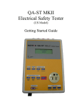
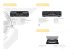
QA-90
MKII Electrical Safety Analyzer
PRODUCT HIGHLIGHTS
OVERVIEW
• Small size - easy to carry
• Can operate completely standalone or by remote
control with the ansur software
• Tests instruments containing modules with different
protection classes in one test run i.e. CF and BF
(defibrillator)
• Tests module separation
• Differential current measurements (optional)
• 11 patient inputs (laboratory style)
• Test according to: IEC 60601.1, IEC 60601.1.1, IEC
60601.2.4, IEC 61010, VDE 751-1:1990, VDE 751-1:
2001, UL 2601.1, AS 3200.1, DB 9801, HEI 95, AAMI.
• Testing against standard or user defined limits
• Automatic, stepwise and manual test modes
• Programmable power up delay time before
measurements
• Integrated keypad
• Internal memory for uploading test sequences and
storing typically up to 200 equipment test results
• Built-in standard A4 protocols for on site
documentation (localised)
• RS-232, Centronics and Bar code interface
The QA-90 represents a new generation of safety testing
equipment. QA-90 is the only automatic safety tester that
can test Instruments containing modules with different
classes of protection in one test run (i.e. CF and BF
defibrillators). It is simple to use. All you need to do is
select the type and class of the equipment to be tested.
When you press START, the QA-90 will execute the tests
prescribed in the selected standard.
The test result can either be printed out immediately or
stored internally in the unit for later use. The QA-90 can
be fully remotely controlled via ansur software. With
ansur, you can make your own test protocols, store the
information on disk and export formatted data to
equipment management databases.
Test sequence:
Individual test sequences may be compiled to satisfy
national and international standards:
IEC 60601.1, VDE 0750 T1/12-91, BS 5724,
UL 2601.1, CAN/CSA-C22.2 No 601.1-M90, AS 3200.1,
NZS 6150:1990, VDE 0751:1990, VDE 0751:2001,
IEC 60601.1.1, IEC 60601.2.4, UL 544, HEI 95, DB9801
and more.
In the interest of product improvement, Metron claims the right to alter specifications without notice.
QA-90 Specifications
VOLTAGE MEASUREMENT:
ACCURACY:
The voltage measurement may be executed in the
following ways:
Range 1:
Resolution:
Accuracy:
0-99.9 µA
0.1 µA
± 2% of full scale ±1 LSD
Range 2:
Resolution:
Accuracy:
100-1000 µA
1 µA
± 2% of full scale ±1 LSD
Range 3:
Resolution:
Accuracy:
1.0-10.0 mA
1 µA
± 1% of full scale ±1 LSD
–
–
–
–
Between lead 1 and 2
Between lead 1 and Earth
Between lead 2 and Earth
Between input/output E+ and E(Floating inputs/outputs).
Range:
Resolution:
Accuracy:
No. of Tests:
0-400V true RMS
0.1V
DC-100 Hz 1% of full scale ±1 LSD
100 Hz-10 kHz 2% of scale ±1 LSD
4 or multiple
CURRENT CONSUMPTION:
The current measurement may be executed in lead
no. 1 (live).
Range 1:
Resolution:
Accuracy:
No. of Tests:
0-1000mA true RMS (@<250VAC)
1mA
±2% of full scale ±1 LSD
1 or multiple
Range 2:
Resolution:
Accuracy:
No. of Tests:
1-16A true RMS (@<250VAC)
1mA
±1% of full scale ±1 LSD
1 or multiple
PROTECTIVE EARTH:
The test current is 25A or 1A, delivered from a
transformer with a maximum idle voltage of 6V. The
measurement can be performed on ground leads or
between E+ and E- (floating inputs/outputs).
Range:
Resolution:
Accuracy:
No. of Tests:
0-2000 mohm
1 mohm
±2% of full scale or 5% of reading
1, 2 or multiple.
INSULATING RESISTANCE:
The measurement of the insulating resistance may be
executed between casing and power unit, or between
patient module and power unit.
Test voltage:
No. of Tests:
500VDC through a 130 kohm
limiting resistor.
1, 2 or multiple.
Range 1:
Resolution:
Accuracy:
1-50 Mohm
1 Mohm
±2% of full scale ±1 LSD
Range 2:
Resolution:
Accuracy:
51-200 Mohm
1 Mohm
±2% of full scale ±1 LSD
LEAKAGE CURRENTS:
All measurements can be performed with a
IEC 601.1 filter (patient equivalent), or without (flat
frequency response). The filter can be exchanged with
filters covering other standards. All measurements can
be performed as true RMS measurements, or AC/DC
measurements.
The following leakage currents are measured:
•
•
•
•
•
•
Earth leakage current
Enclosure leakage current
Differential current
Substitute equipment current
Direct current
Current Fig. 9
No. of Tests:
4
6 or multiple
2
1
2
1
The following leakage currents are measured for each
module:
•
•
•
•
Patient leakage current
6
Mains on applied part leakage current
2
Patient Auxiliary current
6
Floating dual lead measurement of
leakage currents
Multiple
• Substitute patient current
1
In one test run a maximum of 11 modules with
different protection classes may be tested.
GENERAL INFORMATION
TEMPERATURE REQUIREMENTS:
+15°C to +35°C
0°C to +50°C
DISPLAY:
Type:
LCD
Alphanumeric format: 4 lines by
40 characters
Display control:
7 F-keys and a
keypad
FREQUENCY RESPONSE:
DC - 1 MHz (-3dB) with a Crest factor: >2
The test voltage for the mains on applied part
measurement is 110% of the line voltage, delivered
through a limiting resistor of 47 kohm.
DATA INPUT/OUTPUTS (2):
ansur SOFTWARE OFFERS THE
FOLLOWING FEATURES
REMOTE CONTROL:
All functions and tests in QA-90 may be
performed from the PC.
USER-DEFINITION OF TEST STANDARDS:
Select predefined standards or create your own
local/new standard with test limits.
Parallel printer port (1); bi-directional
RS-232C (1) for Computer control.
Bar code interface.
POWER:
From 100 VAC to 240 VAC,
47/63 Hz.
HOUSING:
Metal case
DIMENSIONS:
L x W x H:
305mm x 342mm x 132mm
WEIGHT:
5.8 kg
USER-PROGRAMMABLE TEST SEQUENCES:
Allows user-defined test sequences with a
selection of tests from the selected test standard.
STANDARD ACCESSORIES:
CUSTOMIZED PROTOCOLS:
Create your own protocol format including a header,
checklist, job instructions, a command field and a test
sequence.
RECOMMENDED PRINTERS:
STORAGE AND RECALL:
Protocol formats and data may be stored, recalled,
printed out or transferred to D-base systems.
PRINT OUT:
METRON QA-90 Electrical Safety Analyzer Ver. x.xx QA-90 Serial no.:
Operator
:
Establishment
:
Equipment Code
Module Code
Serial No
Status
Mod.
Manufacturer
Model
Type
Location
: 123
Class
: CL1
: ECG
Group 1 Type
: CF
No of leads 3
:.................................................................................................................................
:.................................................................................................................................
:.................................................................................................................................
:.................................................................................................................................
:.................................................................................................................................
:.................................................................................................................................
:.................................................................................................................................
- - SETUP DATA - -
Test according to
Power-up delay time
Stop at new module
Multiple Protective Earth Test
Protective Earth test current
: IEC601.1
:2
:N
:N
: 25 A
Test Mode
Stop at new power config
Stop before new power config
Multiple Enclosure Tests
External Isolating Transformer
User/Service manual.
HP Desk Jet, Canon Bubble Jet or
compatible
QA-90
ORDERING INFORMATION
Order no:
- - EQUIPMENT INFORMATION - -
: Automa.
:N
:N
:N
:N
TEST <Rapid>
TYPE
LIMIT
RESULT
WARNING
*********************************************************************************
Supply Voltage
Live - Neutral
240.0 V
Supply Voltage
Live - Ground
240.0 V
Supply Voltage
Neutral - Ground
0V
Current Consumption
285.0 mA
Protective Earth
200 mOhm
260.0 mOhm
x
Insulation Resistance
Mains to Case
>200.0 MOhm
Insulation Resistance
Applied Part Mod. 1
>200.0 MOhm
Earth Leakage Current
(OS)
1000 µA
627.0 µA
Earth Leakage Current
(NC)
500 µA
407.0 µA
Earth Leakage Current
(OSRM) 1000 µA
626.0 µA
Earth Leakage Current
(NCRM) 500 µA
413.0 µA
Enclosure Leakage Current
(OS)
500 µA
30.0 µA
Enclosure Leakage Current
(NC)
100 µA
5.0 µA
Enclosure Leakage Current
(OE)
500 µA
409.0 µA
Enclosure Leakage Current
(OSRM) 500 µA
33.0 µA
Enclosure Leakage Current
(NCRM) 100 µA
8.0 µA
Enclosure Leakage Current
(OERM) 500 µA
413.0 µA
Patient Leakage Current
AC Mod. 1, Lead 3 (OS)
50 µA
4.0 µA
Patient Leakage Current
AC Mod. 1, Lead 3 (NC)
10 µA
1.0 µA
Patient Leakage Current
AC Mod. 1, Lead 3 (OE)
50 µA
5.0 µA
Patient Leakage Current
AC Mod. 1, Lead 3 (OSRM) 50 µA
3.0 µA
Patient Leakage Current
AC Mod. 1, Lead 3 (NCRM) 10 µA
0.0 µA
Patient Leakage Current
AC Mod. 1, Lead 3 (OERM) 50 µA
3.0 µA
Patient Auxiliary Current AC Mod. 1, Lead 3 (OS)
50 µA
10.0 µA
Patient Auxiliary Current AC Mod. 1, Lead 1 (NC)
10 µA
1.0 µA
Patient Auxiliary Current AC Mod. 1, Lead 1 (OE)
50 µA
5.0 µA
Patient Auxiliary Current AC Mod. 1, Lead 3 (OSRM) 50 µA
12.0 µA
Patient Auxiliary Current AC Mod. 1, Lead 3 (NCRM) 10 µA
3.0 µA
Patient Auxiliary Current AC Mod. 1, Lead 3 (OERM) 50 µA
6.0 µA
Mains on Applied Part
Mod. 1
(SFC)
50 µA
25.0 µA
Mains on Applied Part
Mod. 1
(SFCRM) 50 µA
35.0 µA
Patient Auxiliary Current DC Mod. 1, Lead 3 (OS)
50 µA
0.0 µA
Patient Auxiliary Current DC Mod. 1, Lead 3 (NC)
10 µA
0.0 µA
Patient Auxiliary Current DC Mod. 1, Lead 3 (OE)
50 µA
0.0 µA
Patient Auxiliary Current DC Mod. 1, Lead 3 (OSRM) 50 µA
0.0 µA
Patient Auxiliary Current DC Mod. 1, Lead 3 (NCRM) 10 µA
0.0 µA
Patient Auxiliary Current DC Mod. 1, Lead 3 (OERM) 50 µA
0.0 µA
Patient Leakage Current
DC Mod. 1, Lead 3 (OS)
50 µA
0.0 µA
Patient Leakage Current
DC Mod. 1, Lead 3 (NC)
10 µA
0.0 µA
Patient Leakage Current
DC Mod. 1, Lead 3 (OE)
50 µA
0.0 µA
Patient Leakage Current
DC Mod. 1, Lead 3 (OSRM) 50 µA
0.0 µA
Patient Leakage Current
DC Mod. 1, Lead 3 (NCRM) 10 µA
0.0 µA
Patient Leakage Current
DC Mod. 1, Lead 3 (OERM) 50 µA
0.0 µA
Unit passed test
Comments
:
Unit failed test
:x
: ..........................................................................................................................
: ..........................................................................................................................
Date-Time/Signature : xx/xx/xxxx-xx.xx ...........................................................................................
Example of printout of a test.
MTD 0402.044.13
while operating
for storage
www.metron-biomed.com
11020: QA-90 MKII Electrical Safety Analyzer
(specify power supply socket)
Accessories:
Various power supply socket including:
European Schuco, French Schuco, UK,
Swiss, Australian, US.
11100:
11110:
10500:
11400:
11401:
11410:
11402:
11451:
11452:
11481:
11482:
11461:
11462:
11471:
11472:
11200:
11201:
11225:
11025:
Carrying Case
Hard Case
Carrying Case, ext. printer
Bar code reader
Isolating transformer 400VA
Isolating transformer 800VA
Test unit (ESA)
E-Input Measuring Cable, 2m, black
E-Input Measuring Cable, 2m, red
E-Input Measuring Cable, 5m, black
E-Input Measuring Cable, 5m, red
Clamp - Crocodile style, black
Clamp - Crocodile style, red
Grip C, black
Grip C, red
ansur QA-90 plug-in
ansur QA-90 plug-in, demo
User manual ansur QA-90 plug-in
User/Service manual QA-90