1
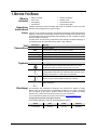
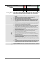
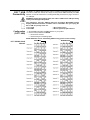
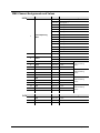
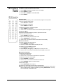
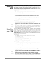
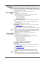
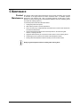
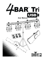
User Manual
TABLE OF CONTENTS
1. Before You Begin ............................................................................................................................ 3
What Is Included ............................................................................................................................................ 3
Unpacking Instructions................................................................................................................................... 3
Claims....................................................................................................................................................................... 3
Text Conventions ........................................................................................................................................... 3
Symbols ......................................................................................................................................................... 3
Disclaimer ...................................................................................................................................................... 3
Product at a Glance ....................................................................................................................................... 4
Safety Notes .................................................................................................................................................. 4
2. Introduction ...................................................................................................................................... 5
Product Overview .......................................................................................................................................... 5
Product Dimensions ....................................................................................................................................... 6
3. Setup ................................................................................................................................................. 7
AC Power....................................................................................................................................................... 7
Fuse Replacement......................................................................................................................................... 7
Power Linking ........................................................................................................................................................... 7
Mounting ........................................................................................................................................................ 8
Orientation ................................................................................................................................................................ 8
Rigging ..................................................................................................................................................................... 8
4. Operation .......................................................................................................................................... 9
Control Panel Operation ................................................................................................................................ 9
Menu Map ...................................................................................................................................................... 9
DMX Linking .................................................................................................................................................. 9
Configuration (DMX) ................................................................................................................................................. 9
DMX Personality and Starting Address ..................................................................................................................... 9
D-Fi™ USB Connectivity.............................................................................................................................. 10
Configuration (D-Fi™ USB) ..................................................................................................................................... 10
DMX Channel Assignments and Values ...................................................................................................... 11
15CH ...................................................................................................................................................................... 11
3-CH ....................................................................................................................................................................... 11
Configuration (Standalone) .......................................................................................................................... 12
Preset Colors .......................................................................................................................................................... 12
Automatic Program ................................................................................................................................................. 12
Program Speed....................................................................................................................................................... 12
Sound-Active Mode................................................................................................................................................. 12
Sound Sensitivity .................................................................................................................................................... 12
RGB Color Mixing ................................................................................................................................................... 12
Wireless Footswitch ..................................................................................................................................... 13
Footswitch Operation .............................................................................................................................................. 13
Footswitch Battery .................................................................................................................................................. 13
Battery Replacement .............................................................................................................................................. 13
IRC-6 Infrared Remote Control .................................................................................................................... 14
IRC-6 Operation ...................................................................................................................................................... 14
Master/Slave Mode (wired) .......................................................................................................................... 15
Master/Slave Mode (D-Fi™ USB) ................................................................................................................ 15
Master/Slave Expansion Mode .................................................................................................................... 16
5. Maintenance ................................................................................................................................... 17
Product Maintenance ................................................................................................................................... 17
6. Technical Specifications............................................................................................................... 18
Returns ............................................................................................................................................... 19
Contact Us .......................................................................................................................................... 20
Page 2 of 20
4BAR™ Tri USB User Manual Rev. 2
1. BEFORE YOU BEGIN
What Is
Included
·
·
·
·
·
·
·
·
4BAR™ Tri USB
Power Cord
Carrying Bag
Tripod stand
Wireless Footswitch
Warranty Card
Quick Reference Guide
Tripod Carrying Bag
Unpacking
Instructions
Carefully unpack the product immediately and check the container to make sure all the
parts are in the package and are in good condition.
Claims
If the box or the contents (the product and included accessories) appear damaged from
shipping, or show signs of mishandling, notify the carrier immediately, not Chauvet. Failure
to report damage to the carrier immediately may invalidate your claim. In addition, keep the
box and contents for inspection.
For other issues, such as missing components or parts, damage not related to shipping, or
concealed damage, file a claim with Chauvet within 7 days of delivery.
Text
Conventions
Convention
1—512
50/60
Settings
Menu > Settings
<ENTER>
ON
Symbol
Symbols
Meaning
A range of values
A set of values of which only one can be chosen
A menu option not to be modified
A sequence of menu options to be followed
A key to be pressed on the product’s control panel
A value to be entered or selected
Meaning
Electrical warning. Not following these instructions may cause
electrical damage to the product, accessories, or the user.
Critical installation, configuration, or operation information. Not
following these instructions may make the product not work, cause
damage to the product, or cause harm to the operator.
Important installation or configuration information. The product
may not function correctly if this information is not used.
Useful information.
Disclaimer
The information and specifications contained in this document are subject to change
without notice. Chauvet assumes no responsibility or liability for any errors or omissions
that may appear in this manual. Chauvet reserves the right to update the existing
document or to create a new document to correct any errors or omissions.
You can download the latest version of this document from www.chauvetlighting.com.
© Copyright 2015 Chauvet. All rights reserved.
Electronically published by Chauvet in the United States of America.
Author
Date
Editor
Updated
R. Isenstadt
07/01/15
A. Leon
07/02/15
4BAR™ Tri USB User Manual Rev. 2
Page 3 of 20
Product at a
Glance
Use on Dimmer
Outdoor Use
Sound-Active
DMX
Master/Slave
Safety Notes
x
x
P
P
P
Auto Programs
Auto-ranging Power Supply
Replaceable Fuse
User-Serviceable
P
P
P
x
Please read the following Safety Notes carefully before working with the product. The
Notes include important safety information about installation, usage, and maintenance.
·
·
·
·
·
·
·
·
·
·
·
·
·
·
·
·
·
·
·
·
Always connect the product to a grounded circuit to avoid the risk of electrocution.
Always disconnect the product from the power source before cleaning or replacing
the fuse.
Avoid direct eye exposure to the light source while the product is on.
Make sure the power cord is not crimped or damaged.
Never disconnect the product from power cord by pulling or tugging on the cord.
If mounting the product overhead, always secure to a fastening device using a
safety cable.
Make sure there are no flammable materials close to the product when operating.
Do not touch the product’s housing when operating because it may be very hot.
The product is not intended for permanent installation.
Always make sure that the voltage of the outlet to which you are connecting the
product is within the range stated on the decal or rear panel of the product.
The product is for indoor use only! (IP20) To prevent risk of fire or shock, do not
expose the product to rain or moisture.
Always install the product in a location with adequate ventilation, at least 20 in
(50 cm) from adjacent surfaces.
Be sure that no ventilation slots on the product’s housing are blocked.
Never connect the product to a dimmer.
Make sure to replace the fuse with another of the same type and rating.
Never carry the product from the power cord or any moving part. Always use the
hanging/mounting bracket.
The maximum ambient temperature (Ta) is 104 °F (40 °C). Do not operate the
product at higher temperatures.
In the event of a serious operating problem, stop using the product immediately.
Never try to repair the product. Repairs carried out by unskilled people can lead to
damage or malfunction. Please contact the nearest authorized technical assistance
center.
To eliminate unnecessary wear and improve its lifespan, during periods of non-use
completely disconnect the product from power via breaker or by unplugging it.
Keep this User Manual for future use. If you sell the product to someone else, be sure that
they also receive this document.
Page 4 of 20
4BAR™ Tri USB User Manual Rev. 2
2. INTRODUCTION
Product Overview
4BAR™ Tri USB
Microphone
Additional Product
Display Mounting Knob
Power Out 1
DMX
In/Out
D-Fi™ USB
Power In
Fuse Holder
Port
Power Out 2
Menu
Buttons
Footswitch
9-Volt Battery
Cover
DIP
Switch
Power
Switch
WARNING! DO NOT plug anything other than a D-Fi™ USB into the USB port. Doing
so may cause damage to the product.
4BAR™ Tri USB User Manual Rev. 2
Page 5 of 20
Product Dimensions
41.3 in
1,050 mm
10.6 in
270 mm
2 in
50 mm
Page 6 of 20
4BAR™ Tri USB User Manual Rev. 2
3. SETUP
AC Power
The 4BAR™ Tri USB has an auto-ranging power supply and it can work with an input
voltage range of 100 to 240 VAC, 50/60 Hz. To determine the product’s power
requirements (circuit breaker, power outlet, and wiring), use the current value listed on the
label affixed to the product’s back panel, or refer to the product’s specifications chart. The
listed current rating indicates the product’s average current draw under normal conditions.
·
Always connect the product to a protected circuit (circuit breaker or fuse).
Make sure the product has an appropriate electrical ground to avoid the risk
of electrocution or fire.
·
To eliminate unnecessary wear and improve its lifespan, during periods of
non-use completely disconnect the product from power via breaker or by
unplugging it.
Never connect the product to a rheostat (variable resistor) or dimmer circuit, even if
the rheostat or dimmer channel serves only as a 0 to 100% switch.
Fuse
Replacement
1.
2.
3.
4.
Wedge the tip of a flat-head screwdriver into the slot of the fuse holder.
Pry the fuse holder out of the housing.
Remove the blown fuse from the holder and replace with a fuse of the exact same
type and rating.
Insert the fuse holder back in place and reconnect power.
Installed fuse
(held by plastic clip)
Safety cap
Spare fuse holder
(inside safety cap)
Disconnect the product from the power outlet before replacing the fuse.
Power Linking
The product provides power linking via the Edison outlet located in the back of the product.
Please see the diagram below for further explanation.
st
1 Product
th
nd
4 Product
rd
5 Product
2 Product
Power Linking
Diagram
3 Product
Additional
Products
th
Additional
Products
You can power link up to 8 4BAR™ Tri USB products on 120 VAC or up to
14 4BAR™ Tri USB products on 230 VAC.
The power linking diagram corresponds to the North American version of the
product ONLY! If using the product in other markets, you must consult with the
local Chauvet distributor as power linking connectors and requirements may differ
in your country or region.
4BAR™ Tri USB User Manual Rev. 2
Page 7 of 20
Mounting
Before mounting the product, read and follow the safety recommendations indicated in the
Safety Notes.
Orientation
The 4BAR™ Tri USB may be mounted in any position; however, make sure adequate
ventilation is provided around the product.
Rigging
·
Before deciding on a location for the product, always make sure there is easy access
to the product for maintenance and programming purposes.
·
Make sure that the structure onto which you are mounting the product can support the
product’s weight. See the Technical Specifications for weight information.
·
When mounting the product overhead, always use a safety cable. Mount the product
securely to a rigging point, whether an elevated platform or a truss.
·
When rigging the product onto a truss, use a mounting clamp of appropriate weight
capacity.
·
When power linking multiple products, mount the products close enough for power
linking cables to reach.
·
The bracket adjustment knobs allow for directional adjustment when aiming the
product to the desired angle. Only loosen or tighten the bracket knobs manually.
Using tools could damage the knobs.
Clamp
Hanging Bolt
Mounting Diagram
Pod Tilt
Adjustment Knobs
Page 8 of 20
Tripod
Insertion Point
IR Sensor
Pod Pan
Adjustment Knob
4BAR™ Tri USB User Manual Rev. 2
4. OPERATION
Control Panel
Operation
To access the control panel functions, use the four buttons located underneath the display.
Please refer to the Product Overview to see the button locations on the control panel.
Button
<MENU>
<UP>
Menu Map
Function
Press to find an operation mode or to back out of the current menu
option
Press to scroll up the list of options or to find a higher value
<DOWN>
Press to scroll down the list of options or to find a lower value
<ENTER>
Press to activate a menu option or a selected value
Mode
Programming Steps
DMX Mode
3-CH
15CH
d 1–d512
Preset Colors
C--
C 1–C 7
Auto Program
Auto
Speed
S--
Sound-Active
DMX Linking
Configuration
(DMX)
DMX Personality
and Starting
Address
Snd
Sound Sensitivity
SenS
RGB Color Mixing
U--
Infrared Mode
Ser
Wireless Foot
Controller
S 1–S100
rF
u 1–u100
ON
r 0–r100
g 0–g100
b 0–b100
ON
OFF
OFF
rF1–16
Description
Sets the DMX starting address
Selects one of the preset colors (red, green,
blue. cyan, magenta, yellow, or white.)
Turns on Auto mode
Adjusts the speed of the automatic program
(fast to slow)
The internal program runs to the beat of the
music
Adjusts the sensitivity of the Sound mode
(low to high)
Adjust the red, green, and blue levels to
create custom colors
Turns on Infrared mode for IRC-6 remote
use
Turns wireless foot control use on or off and
sets channel
The 4BAR™ Tri USB works with a DMX controller. Information about DMX is in the
Chauvet’s DMX Primer, which is available from the Chauvet website
http://www.chauvetlighting.com/downloads/DMX_Primer_rev05_WO.pdf.
Set the product in DMX mode to control with a DMX controller.
1. Connect the product to a suitable power outlet.
2. Connect a DMX cable from the DMX output of the DMX controller to the DMX input
socket on the product.
When selecting a starting DMX address, always consider the number of DMX channels the
selected DMX mode uses. If you choose a starting address that is too high, you could
restrict the access to some of the product’s channels.
The 4BAR™ Tri USB uses up to 15 DMX channels in a 15-CH DMX mode, which defines
the highest configurable address to 498.
If you are not familiar with the DMX protocol, download the DMX Primer from
www.chauvetlighting.com.
To select the starting address, do the following:
1. Press <MENU> repeatedly until 3-CH or 15CH shows on the display.
2. Press <ENTER> and d 1–d512 will show on the display.
3. Use <UP> or <DOWN> to select the starting address.
4. Press <ENTER>.
4BAR™ Tri USB User Manual Rev. 2
Page 9 of 20
D-Fi™ USB
Connectivity
The 4BAR™ Tri USB is able to become a D-Fi™ wireless receiver/transmitter with the use
of the D-Fi™ USB from Chauvet DJ. Simply set the product's DMX Personality and DMX
Address, set the DIP switch D-Fi™ receiving/transmitting channel, then plug it into the DFi™ USB port.
WARNING! DO NOT plug anything other than a D-Fi™ USB into the USB port. Doing
so may cause damage to the product.
Once plugged in, the D-Fi™ USB will take over the product. Wired DMX, manual
display control/menu buttons and IRC-6 will be unavailable until you unplug the
D-Fi™ USB. The priority levels are:
1. D-Fi™ USB
2. Wired DMX
Configuration
(D-Fi™ USB)
D-Fi™ USB DIP Switch
Channels
Page 10 of 20
3. IRC-6 Remote Control
4. Manual Digital Display/Menu Buttons
1. Set the DMX Personality and DMX address on your product.
2. Use the Chart provided to set BOTH:
· the Channel, and then
· the Receiving or Transmitting option.
NOTE: DIP Switch 5 is for Transmitting OR Receiving, please choose carefully.
RECEIVING
TRANSMITTING
4BAR™ Tri USB User Manual Rev. 2
DMX Channel Assignments and Values
15CH
Channel
1
3-CH
Function
Control/Operating
Mode
2
Dimmer
3
Strobe
Value
Percent/Setting
000ó009
RGB Color Mixing
010ó029
Auto Program 1
030ó049
Auto Program 2
050ó069
Auto Program 3
070ó089
Auto Program 4
090ó109
Auto Program 5
110ó129
Auto Program 6
130ó149
Auto Program 7
150ó169
Auto Program 8
170ó189
Auto Program 9
190ó209
Auto Program 10
210ó229
Auto Program 11
230ó249
Auto Program 12
250ó255
Sound-Active mode
000ó255
Dimmer 0–100%
000ó009
No function
010ó255
Slow to fast
4
Red
000ó255
0–100%
5
Green
000ó255
0–100%
6
Blue
000ó255
0–100%
7
Red
000ó255
0–100%
8
Green
000ó255
0–100%
9
Blue
000ó255
0–100%
10
Red
000ó255
0–100%
11
Green
000ó255
0–100%
12
Blue
000ó255
0–100%
13
Red
000ó255
0–100%
14
Green
000ó255
0–100%
15
Blue
000ó255
0–100%
Channel
Function
Value
RGB Color Mixing
(Pod 2)
RGB Color Mixing
(Pod 3)
RGB Color Mixing
(Pod 4)
Percent/Setting
1
Red
000ó255
0–100%
2
Green
000ó255
0–100%
3
Blue
000ó255
0–100%
4BAR™ Tri USB User Manual Rev. 2
RGB Color Mixing
(Pod 1)
Page 11 of 20
Configuration
(Standalone)
Set the product in one of the standalone modes to control without a DMX controller.
·
Connect the product to a suitable power outlet.
Never connect a product that is operating in any standalone mode to a DMX string
connected to a DMX controller. Products in standalone mode may transmit DMX
signals that could interfere with the DMX signals from the controller.
Preset Colors
To run the 4BAR™ Tri USB in Preset Color mode, follow the instructions below:
1. Press <MENU> repeatedly until C-- shows on the display.
2. Press <ENTER>.
3. Use <UP> or <DOWN> to select C 1–C 7.
4. Press <ENTER>.
Automatic
Program
To run the 4BAR™ Tri USB in Automatic mode, do the following:
1. Press <MENU> repeatedly until Auto shows on the display.
2. Press <ENTER>.
Program Speed
To change the auto program speed, follow the instructions below:
1. Press <MENU> repeatedly until S-- shows on the display.
2. Press <ENTER> and Sxxx will show on the display:
3. Use <UP> or <DOWN> to increase or decrease the speed.
4. Press <ENTER>.
Sound-Active
Mode
To run the 4BAR™ Tri USB in Sound-Active mode, do the following:
1. Press <MENU> repeatedly until Snd shows on the display.
2. Press <ENTER>.
Sound Sensitivity
To change the sound sensitivity, follow the instructions below:
1. Press <MENU> repeatedly until Sens shows on the display.
2. Press <ENTER> and uxxx will show on the display:
3. Use <UP> or <DOWN> to increase or decrease the sensitivity.
4. Press <ENTER>.
RGB Color Mixing
To custom mix a color, do the following:
1. Press <MENU> repeatedly until U-- shows on the display.
2. Press <ENTER> and one of the following will show on the display:
·
rxxx (red)
·
gxxx (green)
·
bxxx (blue)
3. Press <ENTER> to cycle through the color settings.
4. When the desired color shows on the display, use <UP> or <DOWN> to increase or
decrease the color value.
5. Repeat steps 3 and 4 until the product outputs as desired.
Page 12 of 20
4BAR™ Tri USB User Manual Rev. 2
Wireless
Footswitch
1
2
3
The included wireless footswitch provides quick access to preset colors, color-change
programs, and sound-activation through the 4BAR™ Tri USB microphone.
To use the footswitch:
1. Connect the 4BAR™ Tri USB to power. Turn the wireless footswitch on.
2. Press <MENU> on the 4BAR™ Tri USB and navigate to rF mode and press
<ENTER>. Choose a channel and press <ENTER>.
3. Press <MENU> on the 4BAR™ Tri USB and navigate to Auto mode and press
<ENTER>.
4.
5.
6.
Footswitch
Operation
Set the DIP switch channel on the wireless footswitch to match the channel set on
the 4BAR™ Tri USB. (Use the DIP Switch Channels image for help)
Press pedal #1 (Colors) to activate Static Color controls. When working, all the
lights will begin in a Static color and FOOr will appear on the Menu display.
Use the chart below to activate the desired function.
Pedal
1
(Static Colors)
2
(Sound/Strobe
Mode)
3
(Blackout)
Action
Functions
White
Red
Green
Blue
Tap Pedal to activate, then Tap to
Yellow
navigate to desired function
Magenta
Cyan
Auto Mode (snap)
Auto Mode (fade)
Tap Pedal
Enter Sound Mode
Hold Pedal Down
Strobe Mode
Tap Pedal Again
Turn off Strobe (Sound Mode only)
Tap Pedal
Black out Fixtures
Hold Pedal Down
Fade to Blackout
Tap Pedal Again/Hold Pedal Again Turn off Blackout/Fade from Blackout
The 4BAR™ Tri USB footswitch will work properly in any mode, with a maximum
unobstructed distance of 50 ft (15.24 m). You must turn on the rF on the 4BAR™ Tri
USB, set the rF channel, and navigate to Auto mode before using the footswitch.
Footswitch
Battery
Battery
Replacement
The wireless footswitch uses a 9-volt battery located under the battery cover on the
bottom of the product, which can be replaced when necessary.
To replace the battery in the wireless footswitch:
1. Turn the power switch to the Off position.
2. Remove the battery cover by removing 2 screws with a Phillips-head screwdriver.
3. Remove the old battery from the housing and unplug it from the leads.
4. Replace with a new 9-volt battery, ensuring that the positive (+) and negative (-)
leads correspond to the correct electrodes on the battery.
5. Place the battery into the housing and cover with the battery cover.
6. Secure the battery cover with the 2 Phillips-head screws.
Do NOT overtighten the screws!
4BAR™ Tri USB User Manual Rev. 2
Page 13 of 20
IRC-6 Infrared
Remote
Control
The 4BAR™ Tri USB is compatible with the IRC-6 infrared remote control from Chauvet.
To activate IR mode, follow the instructions below:
1. Press <MENU> repeatedly until Ser shows on the display.
2. Press <ENTER> to accept.
3. Press <UP> or <DOWN> to select ON or OFF.
4. Press <ENTER>.
IRC-6 Operation
Automatic Mode
Automatic mode will enable you to run the automatic programs on the product.
To turn on Automatic mode (snap):
Press <AUTO> on the IRC-6.
To turn on Automatic mode (fade):
Press <FADE> on the IRC-6.
To adjust the speed of the automatic program:
1. Press <SPEED> on the IRC-6.
2. Press <+> or <–> to either increase or decrease the speed of the program.
Sound-Active Mode
Sound-Active mode will enable the product to respond to the music.
To turn on Sound-Active mode:
Press <SOUND> on the IRC-6.
To adjust sound sensitivity in Sound-Active mode:
1. Press <SENSITIVITY> on the IRC-6.
2. Press <+> or <–> to either increase or decrease sound sensitivity.
Manual Color Control
To choose a specific color with the IRC-6:
1. Press <MANUAL> on the IRC-6.
2. Press any number between 0–9 to choose your color.
To manually control the RGB percentage:
1. Press <MANUAL> on the IRC-6.
2. Press <R> (red), <G> (green), or <B> (blue) to choose your color.
3. Press <+> or <–> to increase or decrease the percentage of each color.
Miscellaneous Operation
To adjust the total output level:
1. Press <%> on the IRC-6.
2. Press <+> or <–> to increase or decrease the output level.
To adjust the strobe rate of the program:
1. Press <STROBE> on the IRC-6.
2. Press <+> or <–> to increase or decrease the strobe rate.
3. Press <STROBE> again to turn off the strobe.
To black out the lights:
1. Press <BLACK OUT> on the IRC-6.
This will turn off all the lights until the button is pressed again.
NOTE: The IRC will not respond to any inputs when Black Out is activated. If the remote
does not respond when a button is pressed, try pressing <BLACK OUT>. You may
have inadvertently activated Black Out.
Page 14 of 20
4BAR™ Tri USB User Manual Rev. 2
Master/Slave
Mode
(wired)
The Master/Slave mode allows a single 4BAR™ Tri USB product (the master) to control
the actions of one or more 4BAR™ Tri USB products (the slaves) without the need of a
DMX controller. The master product will be set to operate in either standalone mode or
with the footswitch, while the slave products will be set to operate in Slave mode. Once set
and connected, the slave products will operate in unison with the master product.
Configure the products as indicated below.
Slave products:
1. Press <MENU> repeatedly until 3-CH or 15CH shows on the display.
2. Press <ENTER> to accept.
3. Set the DMX address to d 1.
4.
Connect the DMX input of the first slave product to the DMX output of the master
product.
5. Connect the DMX input of the subsequent slave products to the DMX output of the
previous slave product.
6. Finish setting and connecting all the slave products.
Master product:
1.
2.
Master/Slave
Mode
(D-Fi™ USB)
Set the master to operate in either Automatic or Sound-Active mode.
Make the master product the first product in the DMX daisy chain.
·
Configure all the slave products before connecting the master to the daisy
chain.
·
Never connect a DMX controller to a DMX string configured for Master/Slave
operation because the controller may interfere with the signals from the master.
·
Do not connect more than 31 slaves to the master.
The D-Fi™ USB allows a single 4BAR™ Tri USB product (the master) to control the
actions of one or more 4BAR™ Tri USB products (the slaves) without the need of a DMX
controller or DMX cables. The master (transmitter) product will be set to operate in either
standalone mode or with the footswitch, while the slave (receiver) products will be set to
operate in Slave mode. Once set and connected, the slave products will operate in unison
with the master product.
Configure the products as indicated below.
Slave products:
1. Press <MENU> repeatedly until 3-CH or 15CH shows on the display.
2. Press <ENTER> to accept.
3. Set the DMX address to d 1.
4. Set D-Fi™ USB to receive on a specific channel, 1–16.
5. Plug in the D-Fi™ USB.
6. Finish setting and configuring all the slave products.
Master product:
1. Press <MENU> repeatedly until the DMX personality the slaves are set to shows on
the display.
2. Press <ENTER> to accept.
3. Set the DMX address to d 1.
4.
5.
6.
Set the master to operate in either Automatic or Sound-Active mode.
Set the D-Fi™ USB to transmit on the D-Fi™ channel the slaves are receiving on.
Plug in the D-Fi™ USB.
·
All products must be set to the same DMX personality, DMX address, and D-Fi™
channel.
·
Configure all the slave products before configuring the master to transmit.
·
Never connect a DMX controller to a D-Fi™ channel configured for Master/Slave
operation because the controller may interfere with the signals from the master.
4BAR™ Tri USB User Manual Rev. 2
Page 15 of 20
Master/Slave
Expansion
Mode
Expansion Mode
(Wired)
The Master/Slave Expansion mode allows a single 4BAR™ Tri USB product (the master)
to control the actions of one or more Tri-color LED USB products (the slaves), such as a
COREpar™ USB, SlimPAR™ USB, or Freedom™ Par, without the need of a DMX
controller, with the use of the optional D-Fi™ USB (not included). The 4BAR™ Tri USB will
be set to operate in either standalone mode or with the footswitch, while the slave products
will be set to operate in slave mode. Once set and connected, the slave products will
operate as directed by the 4BAR™ Tri USB.
For wired Expansion mode, configure the products as indicated below.
Slave products:
1. Set the slave products to 3-channel mode.
2. Set the DMX address of each slave product to correspond with the pod on the
4BAR™ Tri USB it will be synchronized with, as follows:
·
For pod 1, set the address to 1
·
For pod 2, set the address to 7
·
For pod 3, set the address to 13
·
For pod 4, set the address to 19
3. Connect the DMX input of the first slave product to the DMX output of the 4BAR™ Tri
USB.
4. Connect the DMX input of the subsequent slave products to the DMX output of the
previous slave product.
5. Finish setting and connecting all the slave products.
4BAR™ Tri USB:
1. Set the 4BAR™ Tri USB to operate in either standalone mode or with the footswitch
(see Wireless Footswitch).
2. Make the 4BAR™ Tri USB the first product in the DMX daisy chain.
·
·
·
Expansion Mode
(D-Fi™ USB)
Configure all the slave products before connecting the master to the daisy
chain.
Never connect a DMX controller to a DMX string configured for Master/Slave
operation because the controller may interfere with the signals from the master.
Do not connect more than 31 slaves to the master.
For D-Fi™ USB Expansion mode, configure the products as indicated below.
Slave products:
1. Set the slave products to 3-channel mode, 3-CH.
2. Set the DMX address of each slave product to correspond with the pod on the
4BAR™ Tri USB it will be synchronized with, as follows:
·
For pod 1, set the address to 1
·
For pod 2, set the address to 7
·
For pod 3, set the address to 13
·
For pod 4, set the address to 19
3. Set each D-Fi™ USB to receive on a specific channel, 1–16.
4. Plug the D-Fi™ USB products into the slave products.
5. Finish setting and configuring all the slave products.
4BAR™ Tri USB:
1. Set the 4BAR™ Tri USB to operate in either standalone mode or with the footswitch
(see Wireless Footswitch).
2. Set the D-Fi™ USB to transmit on the same D-Fi™ channel as the slaves
(see Configuration (D-Fi™ USB)).
3. Plug in the D-Fi™ USB.
·
·
·
Page 16 of 20
All products must be set to the same DMX personality and D-Fi™ channel.
Configure all the slave products to receive before configuring the master to
transmit.
Never connect a DMX controller to a D-Fi™ channel configured for Master/Slave
operation because the controller may interfere with the signals from the master.
4BAR™ Tri USB User Manual Rev. 2
5. MAINTENANCE
Product
Maintenance
Dust build-up reduces light output performance and can cause overheating. This can lead
to reduction of the light source’s life and/or mechanical wear. To maintain optimum
performance and minimize wear, clean your lighting products at least twice a month.
However, be aware that usage and environmental conditions could be contributing factors
to increase the cleaning frequency.
To clean the product, follow the instructions below:
1. Unplug the product from power.
2. Wait until the product is at room temperature.
3. Use a vacuum (or dry compressed air) and a soft brush to remove dust collected on
the external surface/vents.
4. Clean all transparent surfaces with a mild soap solution, ammonia-free glass
cleaner, or isopropyl alcohol.
5. Apply the solution directly to a soft, lint free cotton cloth or a lens cleaning tissue.
6. Softly drag any dirt or grime to the outside of the transparent surface.
7. Gently polish the transparent surfaces until they are free of haze and lint.
Always dry the transparent surfaces carefully after cleaning them.
4BAR™ Tri USB User Manual Rev. 2
Page 17 of 20
6. TECHNICAL SPECIFICATIONS
Dimensions and Weight
4BAR™ Tri USB
Wireless Footswitch
Length
Width
Height
Weight
41.3 in (1,050 mm)
2 in (50 mm)
10.6 in (270 mm)
20.6 lb (10.8 kg)
12.4 in (315 mm)
5.2 in (132 mm)
1.5 in (38 mm)
0.8 lb (1.8 kg)
7.4 ft (2.25 m)
Tripod Stand
Note: Dimensions in inches rounded to the nearest decimal digit.
Power
Light Source
Photometrics
Thermal
DMX
Ordering
Page 18 of 20
Power Supply Type
Range
Voltage Selection
Switching (internal)
100 to 240 VAC, 50/60 Hz
Auto-ranging
Parameter
120 V, 60 Hz
230 V, 50 Hz
Consumption
69 W
66 W
Operating Current
1A
0.5 A
Power linking current
(products)
8 A (8 products)
8 A (14 products)
Fuse
T 2 A, 250 V
T 2 A, 250 V
Power I/O
U.S./Worldwide
UK/Europe
Power input connector
IEC
IEC
Power output connector
Edison
IEC
Power Cord plug
Edison (U.S.)
Local plug
Type
Power
Lifespan
LED
3W
50,000 hours
Color
Quantity
Current
Tri-color RGB
28
1A
Parameter
Strobe Rate
0 to 25 Hz
Beam Angle
18°
Field Angle
31°
Illuminance @ 2 m
2,330 lux (per pod)
Maximum External Temp.
Cooling System
104 °F (40 °C)
Convection
I/O Connectors
Channel Range
3-pin XLR
3 or 15
Product Name
Item Code
UPC Number
4BAR™ Tri USB
03031060
781462214081
4BAR™ Tri USB User Manual Rev. 2
RETURNS
In case you need to get support or return a product:
· If you are located in the U.S., contact Chauvet World Headquarters.
· If you are located in the UK or Ireland, contact Chauvet Europe Ltd.
· If you are located in Mexico, contact Chauvet Mexico.
· If you are located in Benelux, contact Chauvet Europe BVBA.
· If you are located in any other country, DO NOT contact Chauvet. Instead, contact
your local distributor. See www.chauvetlighting.com for distributors outside the U.S.,
UK, Ireland, Mexico, or Benelux.
If you are located outside the U.S., UK, Ireland, Mexico, or Benelux, contact your
distributor of record and follow their instructions on how to return Chauvet
products to them. Visit our website www.chauvetlighting.com for contact details.
Call the corresponding Chauvet Technical Support office and request a Return
Merchandise Authorization (RMA) number before shipping the product. Be prepared to
provide the model number, serial number, and a brief description of the cause for the
return.
Send the merchandise prepaid, in its original box, and with its original packing and
accessories. Chauvet will not issue call tags.
Clearly label the package with the RMA number. Chauvet will refuse any product
returned without an RMA number.
Write the RMA number on a properly affixed label. DO NOT write the RMA number
directly on the box.
Before sending the product, clearly write the following information on a piece of paper
and place it inside the box:
· Your name
· Your address
· Your phone number
· RMA number
· A brief description of the problem
Be sure to pack the product properly. Any shipping damage resulting from inadequate
packaging will be your responsibility. FedEx packing or double-boxing are
recommended.
Chauvet reserves the right to use its own discretion to repair or replace returned
product(s).
4BAR™ Tri USB User Manual Rev. 2
Page 19 of 20
CONTACT US
WORLD HEADQUARTERS - Chauvet
General Information
Address: 5200 NW 108th Avenue
Sunrise, FL 33351
Voice:
(954) 577-4455
Fax:
(954) 929-5560
Toll free: (800) 762-1084
Technical Support
Voice:
(954) 577-4455 (Press 4)
Fax:
(954) 756-8015
Email:
[email protected]
World Wide Web www.chauvetlighting.com
UNITED KINGDOM AND IRELAND - Chauvet Europe Ltd.
General Information
Address: Unit 1C
Brookhill Road Industrial Estate
Pinxton, Nottingham, UK
NG16 6NT
Voice:
+44 (0)1773 511115
Fax:
+44 (0)1773 511110
Technical Support
Email:
[email protected]
World Wide Web www.chauvetlighting.co.uk
MEXICO - Chauvet Mexico
General Information
Address: Av. Santa Ana 30
Parque Industrial Lerma
Lerma, Mexico C.P. 52000
Voice:
+52 (728) 285-5000
Technical Support
Email:
[email protected]
World Wide Web www.chauvet.com.mx
CHAUVET EUROPE - Chauvet Europe BVBA
General Information
Address: Stokstraat 18
9770 Kruishoutem
Belgium
Voice:
+32 9 388 93 97
Technical Support
Email:
[email protected]
World Wide Web www.chauvetlighting.eu
Outside the U.S., United Kingdom, Ireland, Mexico, or Benelux contact your dealer. Follow their
instructions to request support or to return a product. Visit our website for contact details.
Page 20 of 20
4BAR™ Tri USB User Manual Rev. 2