1
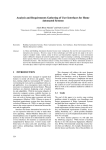
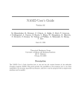
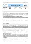
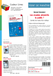
International Journal of Advanced Engineering Technology
E-ISSN 0976-3945
Review Article
HOME AUTOMATION SYSTEM
Sajidullah S. Khan1, Anuja Khoduskar2, Dr. N. A. Koli3
Address for Correspondence
1
Prof. Ram Meghe Institute of Technology & Research, Badnera-Amravati. Maharashtra, INDIA
2
Dr. Panjabrao Deshmukh Polytechnic, Amravati. Maharashtra, INDIA
3
Sant Gadge Baba Amravati University, Amravati. Maharashtra, INDIA
E Mail [email protected]
ABSTRACT
This home automation system mainly focused on the design and implementation of a system that control various appliances
at home. The design is having Micro controller as its heart and this controller board is connected to the server at the home.
Various home appliances are connected to system board with the input/output port. Most of the sensors & transducers such
as temperature, humidity, pressure, are analog. For interfacing these sensors to micro controllers require to convert the
analog output of these sensors to digital so that the controller can read it. This system is scalable as new appliance can be
added with small change in core system appliances can be controlled locally as well as remotely through network
connection.
1. INTRODUCTION
With the fast development in the field of computer
technology, Home automation provides a more
convenient & elegant atmosphere for the family to
compliment and match the lifestyle. Every one in the
family experiences the comfort of automation with
added convenience through integrated control of
scheduled common lifestyle activities performed
everyday. An automated home can provide security,
temperature, lighting, and audio control for comfort,
convenience, and safety. It creates reliable and
coordinated controls to operate home devices
automatically.
The computer network allowed
development of the idea of an online control of
various electrical appliances.
This system needs to enhance home and lifestyle with
clever home automation that can easily monitor and
control home devices; it also provides safety of
equipments, which now operate precisely as per
recommendations. It gives Convenience and comfort
as well as Cost and time saving by optimized
operation for longer life.
As we know because of rapid development of new
technologies such as Java the computer network has
also started to serve as a medium that allows the
monitoring, control, and interaction with machine
and devices. The computer network can be used in
home automation, which provides many features
ranging from efficient use of energy to increased
comfort, greater safety and security.
2. TOOLS REQUIRED:
a) Java is used as Source Development Kit
b) NetBeans 5.5 is used as IDE
c) Tomcat Apache 5.5 is used as the server
IJAET/Vol.II/ Issue II/April-June, 2011/129-132
d) Servlets are used for client - server
communication
e) JNI Java Native Interface is used for
hardware interfacing
f) RxTx Serial Port Library is used to interface
microcontroller
g) Oracle/Microsoft access is used for
database.
This system needs following Hardware as well as
Software Components for its development.
3. Hardware Components
(a) Micro controller 89c51
It is used at the heart of the hardware which is a lowpower,
high-performance
CMOS
8-bit
microcomputer with 4K bytes of Flash programmable
and erasable read only memory.[9] Port 0 is also
configured the multiplexed low order address/data
bus during accesses to external program and data
memory. Port 0 also receives the code bytes during
Flash programming, and outputs the code bytes
during program verification. Port 1 is an 8-bit bidirectional I/O port .Port 1 also receives the loworder address bytes during Flash programming and
program verification. As it is used for connection to
ULN for various high voltage device appliance
control. As inputs, Port 2 emits the contents of the P2
Special Function Register. Port 2 also receives the
high-order address bits and some control signals
during Flash programming and verification. Port 3
also serves the functions of various special features
of the AT89C51. P3.0 RXD used for Serial Input Port
and P3.1 TXD used as Serial Output Port. Port 3 also
receives some control signals such as RST, VPP +5V
dc power, XLAT1, XLAT 2
International Journal of Advanced Engineering Technology
(b) ADC 0808
It is used to convert analog values from sensors to
digital values that can be read by micro controller.
The sensors can be temperature or intrusion detection
sensors, etc.The ADC used to convert analog signals
from sensors to equivalent digital signals that could
be interpret by the microcontroller. The ADC0808,
ADC0809 offers high speed, high accuracy and
repeatability and consumes minimal power.
(c) ULN2803
ULN2803 is the Darlington driver used to control
+12V devices like Relays (Electromagnetic
Switches), Buzzers etc. Relays can be used to control
230V AC devices .this hardware can also be used to
provide feedback to the system via actuators or it can
be used to control electrical devices (using relays).
(d) ULN2803
MAX232 is used to interface micro controller with
PC's Serial Port. It converts PC side voltage levels
(+9 and -9) to micro controller side voltage levels (+5
and 0) and vice versa. It is used for communication
between PC and hardware controller.
(e) Relay
A relay is electrically operated switches, which allow
low power circuits to switch a relatively high
Current/Voltage ON/OFF. For a relay to operate a
suitable pull-in & holding current should be passed
through its coil. Relay coils are designed to operate
from a particular voltage often its 5V or 12V.
The function of relay driver circuit is to provide
the necessary current to energize the relay
coil, when a LOGIC 1 is written on the PORT PIN
thus turning ON the relay. The relay is turned OFF by
writing LOGIC 0 on the port pin .In our system two
relays are used for device control.
4. PROPOSED WORK
System Features
Our system introduces the following features:
1. Visual Menu of home appliances, that user want
to control through application software.
2. The system allows the user to control (On or off)
of home appliances and can be expanded with
site change or without adding any component
(depending
on
the
micro
controller
programming).
3. Outside home Program indoor and outdoor
lights to turn On and Off according to a
schedule.
4. Knowing the devices present state (On or off) at
any time with a single click in software.
IJAET/Vol.II/ Issue II/April-June, 2011/129-132
E-ISSN 0976-3945
5. The system will communicate with user, and
gives information about device's state after
controlling (on or off). If it gets dark, lights
turn On and then Off again a few moments later.
The core of the system consists of two hardware
components: the server at home and the micro
controller board the server is having Java Application
that enables the user to access the appliances through
the network connection. It also talks with the
controller board. The controller board based-on 8-bit
micro controller is used. The controller-board has
digital input and output ports, memory; the controller
board can be programmed using the high level
interactive-C language.
Home appliances are
connected to the digital output of the controller board
via relays .Figure 1 shows the relay configuration for
each device and figure shows the Controller board’s
communication with the home appliances. Feedback
circuit has been designed and implemented to
indicate the device’s actual status after it received the
software command. Once a command is sent to turn a
device ON, the feedback circuit senses the current
and gives an output signal indicating that the device
is ON. Otherwise, the device is not functioning and a
message will pass informing the user that the
command was not executed successfully.
It is the software that manages and controls the
system operation. Two separate applications are
needed; one running on server and the other is
running on the controller board as shown in Fig1.
The control application resides on the controller’s
memory and is written in the C language. This
application o communicates with the circuits
connected to the home appliances.
Second is Java, Java architecture provides a portable,
robust,
high
performing
environment
for
development.
Embedded Controller
I/O
Port
Relay
Lights
Software Program
Feedback
ADC
Feedback
Figure 1. Architecture of System
Temp
Sensors
International Journal of Advanced Engineering Technology
Java also provides portability by compiling the byte
codes for Java, Virtual Machine, which is then
Interpreted on each platform by the runtime
environment, Java also provides stringent, compile
and runtime checking and automatic in order to
ensure solid code.[2] As shown in Figure 2. The
client submits his/her requests it is passed to the Java
application on server that communicates with the
Controller board software to send the actual control
signal to the controller board via the parallel port of
the home server. The controller system is responsible
for taking care of ON\OFF operation of each
appliance.
User request
from
Browser
Java
Application
on server
Controller
of program
Appliances
at Home &
Office
Figure 2. Control and Management of Home
Appliances
5. WORK FLOW:
5.1 Steps to run Server–Side Module:
1. Open the server –side module in Net-Bean &
add JAR folder in libraries.
2. Run the Module for getting welcome Window
3. Clicking on “ok” button user get Main
Window displays.
4. After getting the main window user can test
the hardware by clicking on “Hardware test”
button.
5. For Activating the Hardware Monitor Request
click on “Activate Request Monitor” in that
we can activate all the hardware components
like DC motor, STEPPER motor etc.
5.2 Steps to run the Client–Side Module:
1. Open the Client –side module in Net-Bean &
add JAR folder in libraries.
2. Run the Module then user gets welcome
Window.
3. Clicking on “ok” button to get Main Window.
4. Enter the Valid URL name & Access key and
verify the server connection.
5. Click on ‘Hardware Monitor’ button to see the
status of device.
6. Click on ‘Hardware Control and Monitor”
button to monitor and control the devices
attached at the server-side.
6. FEATURE PROPOSED WORK:
•
The entire apparatus is mounted on a PCB,
Initially temperature transducer, Relays and
buzzers are used for testing the system
operation.
IJAET/Vol.II/ Issue II/April-June, 2011/129-132
E-ISSN 0976-3945
The high voltage high current diver ULN 2803
provides control for motors and Relay from
Port 1 of AT 89C51
• The positive voltage from the sensor is
connected to the ADC as an input.
• The ADC is in turn connected to the
Microcontroller.
The
Analog-to-Digital
Converter collects the input values from
channel and converts the same into a digital
signal and are given as inputs to the microcontroller.
• The digital signal from the ADC is received
and processed using the 89C51 micro
controller. It checks the temperature value for
upper limit using program in it.
• Timing is one important aspect when it comes
to dealing with multiple IC’s, hence we use
Internal Timer of
AT89C51 and on board
crystal oscillator for the timing sequences.
• An external power source of +5V is supplied to
the circuit.
• The PCB is interfaced with the system through
a COM Port. MAX 232 used for
communication.
• The obtained sensor data is reached to the
computer through the serial port and is trapped
by the JAVA code using java Communication
package, used for the purpose of serial port
communications.
• Back-end of the system (designed using
Serialized object) is used to receive the sensor
data and store in the database of the system
through particular time intervals.
• The front-end of the system (designed using
JAVA and other java components) contains a
frame which shows the option buttons to view
the obtained sensor data at the received time
intervals. These devices can be control and
monitor though client as well as server side. If
the user is at client side then access key need to
put for validation and then appliance control is
allowed by server.
7. EXPECTED RESULT:
Special features of the system allow end users to use
a general-purpose personal computer and network to
carry out the control activities remotely. High-speed
network can be used to reduce the delay time
between the transitions of streams from client to
server. The system also provided feedback to the end
users.
•
International Journal of Advanced Engineering Technology
REFERENCES
[1]. A. R. Al-Ali and M. AL-Rousan, “Java-based home
automation system,” IEEE Trans.
Consumer
Electron. vol. 50, no. 2, pp. 498-504., May 2004.
[2]. Brinkschulte, U, Krakowski, C, Kreuzinger, J and
Ungerer, T, “A multithreaded Java microcontroller for
thread-oriented real-timeevent-handling “International
Conference on Parallel Architectures and Compilation
Techniques, 1999 Page(s):34 – 39.
[3]. Ximin ZHANG, Jinding SUN and Lihua ZHOU
”Development of an Internet Home Automation
System using java & Dynamic DNS Services”, IEEE
Computer Society, Proceedings of the Sixth
International Conference on Parallel and Distributed
Computing, Applications and Technologies 2005,
pages 537-539.
[4]. Van Der Weff, M. Gui X.Xu, W.L. “A Mobile based
home automation system” second International Nov
2005 pp 40.
[5]. Mahmoud shaker Nasr and Fahtha H. A.salem Azwai,
"Friendly home automation system using cell phone
and J2ME with feedback instant voice messages,"
Consumer Electronics, IEEE Transactions on,
Volume50 On page(s):498-504, May2004.
[6]. MCS® 51 Microcontroller Family User's Manual from
(page 1-50).
IJAET/Vol.II/ Issue II/April-June, 2011/129-132
E-ISSN 0976-3945