1
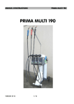
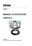
PRIMA
PRIMA SRL
I - 35020 ALBIGNASEGO / PD Via Garibaldi, 28
Tel. +39 049 8625963 r.a. - Fax. +39 049 8625968
P. IVA 00069400281
http: www.primasald.com
e-mail: [email protected]
INSTRUCTIONS MANUAL
PUNTO TOP
PUNTO PLUS
PUNTO ROBOSTAR
ATTENTION
Carefully read this manual before using the spot welder.
This manual refers to the following spot welders: Punto Top, Punto Plus, Punto RoboStar
This manual is supplied by PRIMA srl without any guarantee. PRIMA srl reserves the
right to apply to this manual, at any time and without notice, modifications due to typing
errors, inaccuracy of contents or improvements of the programs and devices.
In any case, possible modifications will be integrated in the subsequent editions of this
manual. In no case PRIMA srl will be liable for direct, indirect, extraordinary, accidental or
consequential damage caused by the use or the inability to use the spot welder or this
documentation.
Copyright © 2011 Prima srl
Via G. Garibaldi, 28
35020 Albignasego/PD - Italy
All rights reserved. First edition 2011. Printed in Italy.
p. 2
PRIMA
MOVABLE SPOT WELDER SERIES: PUNTO
•
p. 03/35
This machine complies with the 89/392/CEE directives and subsequent modifications
and supplements.
CONTENTS
Notes and precautions……………………….…………. p. 4
Definition of the terms………………………………….. p. 6
Features of the spot welder……………………….…… p. 6
General information…………………………………….. p. 6
Technical specifications and performances………….. p. 7
Packing-Unpacking-Storage…………………………….p. 8
Lifting – Dimensions - Weight………………………….. p. 9
Installation…………………………………………..…… p. 10
Precautions and checks…………………………………p. 10
Electrical connections……………………………….….. p. 11
Compressed air connection……………………………. p. 11
Cooling circuit………………………………………….… p. 12
Controls, Adjustments, Calibration……………………. p. 13
Welding gun……………………………………………… p. 13
Arm calibration…………………………………………... p. 13
Front panel………………………………………………. p. 14
Welding control PuntoTop-PuntoPlus………………….p. 15
Welding control RoboStar……………………………….p. 17
Start-up…………………………………………………… p. 19
Limit of use………………………………………………. p. 19
Environment………………………………………………p. 20
Starting the machine……………………………………. p. 20
Handling and positioning……………………………….. p. 21
Maintenance………………………………………………p. 23
Scheduled maintenance…………………………….…. p. 23
Extraordinary maintenance…………………………….. p. 24
Emergency……………………………….……………….p. 25
Disassembly-Disposal………………………………….. p. 25
Troubleshooting…………………………………………. p. 26
Spare parts………………………………………………. p. 28
Wiring diagram…………………………………………... p. 32
Pneumatic diagram………………………………………p. 34
Cooling system diagram……………………………... p. 35
PRIMA
p. 04/35
MOVABLE SPOT WELDER SERIES: PUNTO
• This machine complies with the 89/392/CEE directives and subsequent modifications
and supplements.
NOTES AND PRECAUTIONS
Have the electrical connections made by qualified personnel in compliance with the
relevant Laws and safety Codes. Make sure that the power box is properly connected to
the grounding system and that it is complying with the CEI EN 60 204/1 Standard.
WARNING
Do not use cables with damaged insulation, loose connecting terminals or inadequate
section.
Do not operate the spot welder in a humid or wet environment or in the rain.
Always disconnect the machine from the supply systems during installation or checking
and maintenance operations.
Bring flammable materials or substances to a sufficient distance (at least 10 meters) from
the working area.
It is extremely dangerous to weld (spot weld) containers or tanks which have contained
liquid or gaseous substances or combustibles – because explosions may occur.
During normal spot welding, and especially when welding galvanized, painted or oil
contaminated metal, smoke will be produced. Make sure there is an adequate air change
or a suitable extraction systems.
Always protect your eyes with special safety glasses, wear gloves, apron and protective
clothing without metal accessories.
PRIMA
MOVABLE SPOT WELDER SERIES: PUNTO
•
p. 05/35
This machine complies with the 89/392/CEE directives and subsequent modifications
and supplements.
During welding operations the machine generates magnetic fields. Pay attention to the
attraction of iron bearing working residues.
Watches as well as other mechanical, electric and/or electronic devices can be damaged.
WARNING: Persons with pacemakers or other cardiac devices must absolutely not
use the machine.
In case of water leaks from the cooling circuit, immediately disconnect the machine from
the power supply and look for the leak. Possible repairs must be made by qualified
personnel.
The operator must have adequate knowledge and training in the use and the resistance
welding procedure with this machine.
Do not allow unauthorized persons to access the working area; avoid that more then one
person works simultaneously on the same machine.
The spot welder is equipped with balancing and movable mechanisms. Therefore all
precautions must be taken to avoid hazardous situations.
PRIMA
p. 06/35
MOVABLE SPOT WELDER SERIES: PUNTO
• This machine complies with the 89/392/CEE directives and subsequent modifications
and supplements.
DEFINITION OF THE TERMS
Refer to the UNI EN 292 Standard for the definition of the terms used in this manual.
FEATURES OF THE MACHINE
GENERAL INFORMATION
MOVABLE RESISTANCE WELDING STATION
Main components and controls:
•
•
•
•
•
•
•
Mobile trolley of metal tubes and frame with wheels, covering of thermoplastic ABS
plastic.
Balancing arm of steel tubes, provided with gas springs, hinged joints mounted in ball
bearings.
Welding gun with incorporated transformer, vacuum sealed and water cooled.
Electro-pneumatic operation of welding gun closure.
Manometer unit for welding pressure regulation at the electrodes.
Independent cooling system with closed circuit.
Counterweight for balancing.
This machine has been manufactured in compliance with the following regulations:
•
Machine Safety Directive 89/392/CEE, 91/368CEE, 93/44/CEE, 93/68/CEE
•
89/336/CEE Directive, electromagnetic compatibility.
•
73/23/CEE Directive, low voltage electric material.
•
EN 50063 Standard, building and installation of resistance welders.
•
UNI EN 292/1 and 292/2 Standard, machinery safety.
p. 07/35
PRIMA
MOVABLE SPOT WELDER SERIES: PUNTO
•
This machine complies with the 89/392/CEE directives and subsequent modifications
and supplements.
TECHNICAL SPECIFICATIONS AND PERFORMANCES
See table of general technical data (fig.1).
DIMENSIONS
Working height
Maximum radius
Hinged joints
Dimensions (rest position) WxLxH
Gun dimensions
Weight
Punto Top
mm
mm
qty.
mm
mm
kg
ELECTRICAL specifications
Punto Plus
50÷2500
50÷2500
2300
2300
7
7
1030x815x1250 1030x815x1250
130x320x320
130x370x320
150
150
Robo Star
50÷2500
2300
7
1030x815x1250
130x370x350
165
Punto Top
Punto Plus
Robo Star
6
2+2
1/400/50
2,7
8,8
7,5
8
24
16
8
2,5+2,5
1/400/50
5
13
12.3
9
65
32
9
3x2,5
3/400/50
12.5
13
13
9
52
32
MECHANICAL features
Punto Top
Punto Plus
Robo Star
Cooling (closed circuit)
Compressed air operation (ISO 6431)
Electrode force at 800 kpa (8 bar)
daN
Air consumption for 1000 spots
m³
Noise level (ISO 7779)
dB A
Ambient temperature
°C
Air humidity
%
Throat depth
mm
Electrode arm diameter
mm
Electrode arm distance
mm
liquid
pneumatic
190
0,6
<65
5÷35
<90
120÷500
20
120
liquid
pneumatic
300
0,8
<65
5÷35
<90
120÷500
20
120
liquid
pneumatic
455 (6.5 bar)
0,9
<65
5÷35
<90
120÷600
25
120
Nominal power at 50%
Welding thickness
Input voltage (*)
Secondary no-load voltage
Secondary short-circuit current
Secondary welding current
Duty cycles
Rated power
Fuses for 400 V
KVA
mm
1ph V/Hz
V
KA
KA
%
KVA
A
Fig. 1
PRIMA
p. 08/35
MOVABLE SPOT WELDER SERIES: PUNTO
• This machine complies with the 89/392/CEE directives and subsequent modifications
and supplements.
PACKING
The spot welder comes packed on a special pallet, fastened with steel strips and wrapped
in a plastic film.
When shipped in a container by sea, the spot welder is sealed with salt resistant plastic
material.
On request, the spot welder is delivered on a pallet with wooden case and fastened with
steel strips.
UNPACKING
•
Remove the panels of the wooden case (if provided).
•
Remove the steel strips.
•
Remove the protective plastic material.
•
Lift the spot welder with suitable means and remove the pallet.
CAUTION: The packing materials – wood, nails, plastics etc. – must not be left within the
reach of children, as they could be a source of danger.
The packing materials must be subdivided and disposed of in compliance with the
applicable Codes.
STORAGE
The spot welder must be stored at a temperature between 0 and 40 °C in a dry place,
protected from weather and far from heat sources.
PRIMA
p. 09/35
MOVABLE SPOT WELDER SERIES: PUNTO
• This machine complies with the 89/392/CEE directives and subsequent modifications
and supplements.
LIFTING, DIMENSIONS AND WEIGHT
INSTRUCTIONS FOR LIFTING
The spot welder must be moved with care, avoiding shocks and dropping which could
damage the machine.
Figure 2, page 9 shows the points the lifting devices are to be attached to.
Fig. 2
DIMENSIONS AND WEIGHT
The closed and packed spot welder on pallet, or at request in a wooden cage, has the
following dimensions and weight:
on pallet (8 kg)
W = width
L = depth
H = height
Weight:
1000 mm
1200 mm
1250 mm
150 kg
in cage (20 kg)
W = width 1000 mm
L = depth 1200 mm
H = height 1300 mm
PRIMA
MOVABLE SPOT WELDER SERIES: PUNTO
•
p. 10/35
This machine complies with the 89/392/CEE directives and subsequent modifications
and supplements.
INSTALLATION
PRECAUTIONS AND CHECKS
CAUTION: During all installation and connection operations, the machine must be
absolutely isolated from the power supply line.
CAUTION: Installation must be made by qualified personnel in compliance with the
applicable regulations and in accordance with the instructions of the manufacturer.
CAUTION: Before connecting the machine to the mains supply, make sure that the data
on the nameplate of the spot welder correspond to the voltage and frequency of the mains
supply available on site.
Electrical safety of the spot welder is obtained only when connected to an efficient
grounding system made in compliance with the applicable Regulations.
Have qualified personnel check the system for functional efficiency.
The Manufacturer cannot be held liable for possible damage caused by absence or
inefficiency of the grounding system.
Check that the installed power on the electric supply meter as well as the cables of the
electrical plant are adequate for the rated power of the spot welder.
CAUTION: In case the user makes modifications, alterations or changes of the spot
welder or integrates it in a plant, any liability of the Manufacturer decays and the user is
obliged to remove the CE label.
The non-observance of the above instructions will render the safety system provided by
the Manufacturer ineffective, causing serious risks of personal injuries and material
damage.
PRIMA
p. 11/35
MOVABLE SPOT WELDER SERIES: PUNTO
• This machine complies with the 89/392/CEE directives and subsequent modifications
and supplements.
ELECTRICAL CONNECTION
The electrical connection of the spot welder to the mains must be made by qualified
personnel.
The electrical connection must be made in compliance with the prescriptions of the EN
50063 CEI 26-6 and CEI 64/8 Standard - installation of resistance welders (spot welders)
- to a grounded power box provided with a differential circuit breaker having an adequate
capacity for the power of the spot welder (tab.1, p.7, Electrical Features) and complying
with the CEI EN 60204/1 Standards.
Make sure that the size of the electrical line (conductor section) and the capacity of the
fuses are adequate.
Caution: The spot welder is SINGLE PHASE and provided with a power cord with two
leads, plus a third lead intended only for connection to the grounding system; therefore it
can be connected to a single phase power supply, or to a three phase power supply of
which only two of the three available phases will be used.
COMPRESSED AIR CONNECTION
The spot welder must be connected to the compressed air supply (fig.1, p.7, Mechanical
Features) using an appropriate rubber hose provided with a female quick coupler to be fit
to the male coupler to be installed on the ¼” gas sleeve of the spot welder (fig.3, p.11).
Fig. 3
PRIMA
MOVABLE SPOT WELDER SERIES: PUNTO
•
p. 12/35
This machine complies with the 89/392/CEE directives and subsequent modifications
and supplements.
COOLING CIRCUIT
An efficient closed circuit cooling system provided with a 4-liter tank, a pump for forced
liquid circulation, fan and air/water heat exchanger provides for integral cooling of the
transformer and the welding arms.
To fill up the cooling liquid level use the special filler plug.
Each time you start the spot welder, check the cooling system for proper circulation by
checking the return flow situated inside the filler plug (fig.4, p.12).
WARNING: Welding operations performed with no or with insufficient cooling liquid
circulation can cause damage through overheating and shut off the spot welder following
to the activation of the safety thermostats.
Check the cooling liquid level on a regular basis in accordance with the use.
CAUTION: Always replace only one welding arm at a time, in this way you avoid
discharge and loss of the cooling liquid contained in the piping of the circuit.
Fig. 4
PRIMA
MOVABLE SPOT WELDER SERIES: PUNTO
•
p. 13/35
This machine complies with the 89/392/CEE directives and subsequent modifications
and supplements.
CONTROLS – ADJUSTMENTS - CALIBRATION
WELDING GUN
The two-position welding switch is located on the gun handle (fig.5, p.14); pushing the
switch forward only closes the gun, pushing the switch backwards also activates the
welding cycle.
Note: When the switch is released at any time during the welding cycle, the cycle is
interrupted and the welding gun opens.
To obtain the wide opening of the gun, press the appropriate release lever; to reset the
normal working opening of the arms, press the welding switch forward.
After every welding arm replacement the welding gun must be balanced again (fig.6,
p.14). Loosen the locking screws and position the gun by sliding the special bracket in the
support. Upon reaching the proper position, lock the screws.
Note: Replace one welding arm at a time to avoid loss of the cooling liquid contained in
the piping.
ARM CALIBRATION
The suspension and balancing arm is factory calibrated and does not require further
adjustments. If adjustment should become necessary, pay much attention and proceed as
follows (fig.7, p.14):
a) Lift the balancing arm to the stop.
b) Loosen the locking nuts using a wrench and counter-wrench.
c) Act on the locking screws. Fastening the screws raises the lifting point of the gas
spring and lowers the thrust, loosening them increases the thrust. When you have
found the ideal position, carefully lock the nuts and counter-nuts.
CAUTION: ONLY A FEW ROTATIONS OF THE LOCKING NUTS ARE ENOUGH TO
CONSIDERABLY CHANGE THE BALANCING BEHAVIOR OF THE ARM.
PRIMA
MOVABLE SPOT WELDER SERIES: PUNTO
•
p. 14/35
This machine complies with the 89/392/CEE directives and subsequent modifications
and supplements.
FRONT PANEL
The front panel of the spot welding machine contains the main welding control switch as
well as the pressure regulation unit with manometer for the compressed air.
PRIMA
P. 15/35
MOVABLE SPOT WELDER SERIES: PUNTO
• This machine complies with the 89/392/CEE directives and subsequent modifications
and supplements.
WELDING CONTROL (PUNTO TOP – PUNTO PLUS)
Micro Digital 4 microprocessor-controlled welding control (with automatic tool identification
only with specially designed machines).
CONTROLS (fig.10, p.16)
When turning the machine on, which is done by means of the main switch, the welding control LEDs light,
indicating the proper power supply.
1) THERMOSTAT INDICATOR
Red LED that lights up in case of overheating of the welding circuit due to heavy operation or lack of cooling
liquid. The safety thermostat stops the spot welder leaving only the cooling circuit in operation.
2) ENERGY CONTROL SELECTOR
Activates the energy control function. It is used when welding partially oxidized surfaces or surfaces
contaminated with oil, paint etc.
3) HEATING SELECTOR
Activates the heating function and automatically sets the optimum values. It is used for operation with
carbon electrodes.
4) PULSE SELECTOR
Activates the pulse function. It is used for welding of metal with a major thickness or under heavy welding
conditions (deformed or greasy pieces etc).
5) APPROACH TIME (decrease)
6) APPROACH TIME (increase)
Setting of the approach time; period of time between the activation of the welding switch and the beginning
of welding. Adjustment ranges from 5 to 50 cycles.
7) WELDING TIME (decrease)
8) WELDING TIME (increase)
Setting of the welding time. This will count a whole number of cycles with beginning and end in alternated
semi-cycles. Adjustment ranges from 1 to 50 cycles.
9) WELDING CURRENT (decrease)
10) WELDING CURRENT (increase)
Setting of the welding amperage. Adjustment ranges from 100% to 10%, (power of the spot welder).
11) PULSES (decrease)
12) PULSES (increase)
Setting of the number of pulses. Adjustment ranges from 1 to 5 pulses, each of 5 mains cycles.
PRIMA
p. 16/35
MOVABLE SPOT WELDER SERIES: PUNTO
• This machine complies with the 89/392/CEE directives and subsequent modifications
and supplements.
Fig.10 MICRO DIGITAL 4 type welding control front panel
PRIMA
p. 17/35
MOVABLE SPOT WELDER SERIES: PUNTO
• This machine complies with the 89/392/CEE directives and subsequent modifications
and supplements.
WELDING CONTROL (ROBOSTAR):
MANUAL MODE
Use this regulation to use the welder a san inverter generator with different regulations of
squeeze time, welding time, welding power, maintenance time, electrode force..
Display: indicates
the welding current.
Push on (+) and (-)
keys to change
values.
(-) key
reduces the
values.
Display: indicates the value of
welding parameters, squeeze time,
welding time, welding current,
electrode force (compressed air
force) and maintenance time.
(+) key
increases
the values.
Welding
parameters
icon.
Compressed
air icon.
Indicates: squeeze
time, welding time,
welding current,
compressed air
pressure and
maintenance time.
Touch the button
until the expected
icon lights up.
p. 18/35
PRIMA
MOVABLE SPOT WELDER SERIES: PUNTO
This machine complies with the 89/392/CEE directives and subsequent modifications and supplements.
SYNERGIC MODE
Resistance synergic welding (SPOT), indicates the regulation system, in which it is not
necessary regulate every welding parameter, select on frontal panel the basic parameters
that are: hardness and thickness of workpiece and type of arms, all welding parameters
are set up automatically by the machine with inside programs.
Display: indicates
the hardness of the
work piece.
Selection
hardness key:
touch the button
until the
expected icon
lights up.
Display:
indicates model
of
electrodes(arm
s)
Selection
electrodes key:
touch the
button until the
expected icon
lights up.
Display:
indicates
metal
thickness.
Selection metal
thickness key:
touch the button
until the
expected icon
lights up.
Display: indicates
welding current:
push (+) or (-) key
sto change values.
(-) key
reduces
the values
(+) key
increases
the
values.
Display: indicates
alternately : welding
time or electrode
force.
Select manual or
synergic mode:
touch the button
until the expected
icon lights up.
Welding time
and electrode
force icons.
Indicates welding
time and
electrodes force,
touch the button
until the expected
icon lights up.
PRIMA
MOVABLE SPOT WELDER SERIES: PUNTO
p. 19/35
This machine complies with the 89/392/CEE directives and subsequent modifications and supplements.
START UP
WARNING: Remember some safety precautions to be taken in order to avoid hazardous
situations.
•
The operator must have adequate knowledge and training in resistance welding
procedures (spot welding) with this type of spot welder.
•
Do not allow unauthorized persons to access the working area.
•
Avoid that more then one person works simultaneously on the same spot welder.
•
The spot welder is equipped with moving elements, balancing arm, welding arms and
electrodes; therefore all precautions must be taken to prevent these elements from
striking against persons or things and to prevent hands or other parts of the body from
squeezing between the welding arms.
CAUTION:
Do not wear magnetic metal objects as rings, bracelets, watches etc. during welding
operations, because these objects can be violently attracted by the magnetic field
generated by the spot welder or considerably overheated due to the Joule effect and
cause burns.
The operator must wear safety glasses, gloves and an apron to protect himself against
sparkling incandescent particles, burns and cuts in the hands.
Note: The individual protective systems must be in compliance with the applicable
Regulations.
LIMIT OF USE
This spot welder has been designed, dimensioned and manufactured for resistance
welding on thin steel sheet (fig.1, p.7, Electrical Features). Any use with different welding
procedures, non-iron metals, different sheet thickness or with more duty cycles as
indicated may affect proper operation and cause damage to the spot welder.
Therefore the machine must be destined only for the use foreseen and described in this
manual, any other use is to be considered improper and may cause hazards to the
operator's safety and material damage.
The manufacturer cannot be held liable for possible personal injuries or material damage
arising from improper or unreasonable use.
PRIMA
p. 20/35
MOVABLE SPOT WELDER SERIES: PUNTO
• This machine complies with the 89/392/CEE directives and subsequent modifications
and supplements.
ENVIRONMENT
Working ambient temperature: 5°C to 35°C.
Working air humidity: lower than 90%.
STARTING THE MACHINE
WARNING: The first start-up of the spot welder must be made by qualified personnel.
Before performing any welding operation, a series of checks and adjustments must be
made.
•
Make sure the electrical connection has been made properly and in compliance with
the applicable Regulations.
•
Check the connection to the compressed air supply and adjust the pressure value.
•
Check the diameter and the good state of the welding electrode tips.
•
On the welding control front panel, set all parameters according to the type and quality
of the sheet metal to be spot welded: approach time, welding time, welding current,
holding time, interval time, if the automatic spot repetition function is used, energy
control in case of oxidized or dirty metal sheets.
•
The main switch When turning the machine on, which is done by means of the main
switch, the welding control LEDs light, indicating the proper power supply.
•
Check the cooling circuit for proper circulation and liquid level (fig.4, p.12).
•
Position the welding gun on the metal sheets to be welded and press the welding
switch located on the gun handle backwards (fig.5, pag.14), so that the sheets are
squeezed with the pre-set force between the electrodes and the welding current
passes for the pre-set period of time. Wait until the electrodes automatically open, then
release the button at the end of the cycle.
•
To lock the sheets between the gun electrodes during the pre-welding phases, press
the switch forward. When releasing the switch the gun opens. To pass over to welding
with the sheets remaining locked between the electrodes, quickly slide the finger on
the switch from the front position to the back position to start the welding cycle.
PRIMA
p. 21/35
MOVABLE SPOT WELDER SERIES: PUNTO
• This machine complies with the 89/392/CEE directives and subsequent modifications
and supplements.
•
To reach welding points behind high sheet rims, press the release lever (fig.5, p.14) to
obtain the wide opening of the gun. To reset the normal working opening of the arms,
press the welding switch forward.
Note: When releasing the switch at any time during the welding cycle, the cycle is
interrupted and the welding gun opens.
•
WARNING: At the tip of the electrodes a force of approximately 150 kg is applied. Do
not put your hands between the arms and the electrodes of the gun, pay much
attention – danger of squeezing (fig.11, p.20).
•
Avoid spot welding without metal sheets between the electrodes.
•
Turning off: operate (open) the main switch. The spot welder and the power supply
indicator turn off.
WARNING: The spot welder must be used by trained personnel.
HANDLING
CAUTION: Use particular care in handling and positioning the spot welder in the shop
during the welding operations.
•
The spot welder is equipped with mobile and balancing elements, therefore all
precautions must be taken to avoid dangerous situations to arise.
•
The spot welder must be moved and positioned using the handle while the balancing
arm must be lowered to its rest position (fig.12, p.20).
•
Do not move the spot welder when the balancing arm is raised, because this could
cause personal injuries or material damage.
•
Do not move the spot welder with the balancing arm in the upper position; this could
cause hazards due to possible tilting of the welder.
•
Do not allow unauthorized personnel to access the working area; avoid that more then
one person works simultaneously on the same machine.
•
Before operation check the machine for level and stable positioning.
PRIMA
p. 22/35
MOVABLE SPOT WELDER SERIES: PUNTO
• This machine complies with the 89/392/CEE directives and subsequent modifications
and supplements.
PRIMA
MOVABLE SPOT WELDER SERIES: PUNTO
•
p. 23/35
This machine complies with the 89/392/CEE directives and subsequent modifications
and supplements.
MAINTENANCE
WARNING: Never remove the panels of the spot welding machine and access the interior
without having previously removed the power cord from the power supply box.
WARNING: Possible checks inside the spot welding machine, performed when energized,
can cause heavy electrical shocks generated by direct contact with current carrying parts.
WARNING: Maintenance must be performed by qualified personnel.
SCHEDULED MAINTENANCE
Maintenance of components and wear materials must be performed on a regular basis
once a week or more often according to the use and the environmental conditions as
listed below.
•
Check the welding electrodes every 100 spot welds; restore the original diameter of
the tip (circa 4÷5 mm). Using a fine-grained file, remove iron residues that come off the
sheet metal as well as the craters that have formed.
•
Check and carefully clean the locking seats of the arms in the gun as well as the
extremities of the welding arms.
•
Check the circulation and the level of the cooling liquid (fig.4, p.12).
•
Check the state of the power cord, the tightness of the compressed air hoses and
make sure the supply cable bushing between the machine and the gun is undamaged.
•
Inspect the spot welder and remove dust and particles that may have deposited on the
various components.
PRIMA
p. 24/35
MOVABLE SPOT WELDER SERIES: PUNTO
• This machine complies with the 89/392/CEE directives and subsequent modifications
and supplements.
Once a month, inspect the balancing arm / welding gun unit, and particularly:
A) Pivots, screws and locking screws of the gas springs.
B) Pivots and screws of the joints mounted in ball bearings.
In regular intervals and with a frequency based on the use, at least every 4 months, check
all electrical contacts of the secondary circuit of the spot welding machine, the low voltage
supply and the flexible connection; make sure the screws are tightened and that there are
no traces of oxidation; check the cooling circuit for liquid leaks and inspect all pneumatic
and hydraulic hoses; check the hose clips for perfect seal.
The proper maintenance assures high welding performance of the machine and limits
consumption and current absorption.
In the machine interior, inspect all electric, pneumatic, hydraulic and mechanical
components. Remove dust and particles that may have deposited on the various
components.
EXTRAORDINARY MAINTENANCE
Repair and replacement of components of the welding machine, if required, must be
performed by qualified personnel using only original spare parts.
WARNING: Replacement of components with non original spare parts and/or alterations
of the machine causes the decay of any liability of the manufacturer for personal injuries
or material damage that may arise.
PRIMA
p. 25/35
MOVABLE SPOT WELDER SERIES: PUNTO
• This machine complies with the 89/392/CEE directives and subsequent modifications
and supplements.
EMERGENCY
FIRE
In case of fire, use only powder extinguishers complying with the applicable Regulations.
WARNING: NEVER USE LIQUID FIRE EXTINGUISHERS, BECAUSE THE MACHINE
COULD BE ENERGIZED.
WARNING: WHEN BURNING, SOME PARTS OF THE MACHINE MAY PRODUCE
TOXIC COMBUSTION GASES OR SMOKE.
DISASSEMBLY - DISPOSAL
CAUTION:
If the machine is to be put out of service, provide for disassembly and disposal according
to the applicable Regulations.
Subdivide the different materials:
•
Metal
•
Electric material
•
Electronic material
•
Plastic and rubber material
ATTENTION: Waste materials must be subdivided and disposed of in compliance with the
applicable Laws.
PRIMA
p. 26/35
MOVABLE SPOT WELDER SERIES: PUNTO
• This machine complies with the 89/392/CEE directives and subsequent modifications
and supplements.
TROUBLESHOOTING
Below is a list of possible problems and malfunctions that may occur and the remedies to
eliminate them
PROBLEM
CAUSE
REMEDY
The spot welder does not turn
on.
Connection error.
Control panel switch open.
Check connection and control
panel.
The welding gun does not
close after having pressed the
welding switch.
Switch defective.
Solenoid valve fuse burnt out,
short circuit in coil.
Welding control defective.
Control fuse burnt out.
Check switch.
Check solenoid valve fuse,
coil and control unit; perform
tests with the solenoid valve
manual control.
Check the welding control.
When pressing the welding
switch, the welder performs
the cycle without spot welding.
Welding switch Weld / No
Weld in position No weld.
Welding control defective.
Activate welding function.
Check the welding control.
The spot welder does not
weld, the red overheating LED
lights.
Activation of
thermostats.
safety
Check liquid circulation and
temperature and wait until
thermostats are reactivated.
Execution of spot welds with
sparkling of melted material.
Holes and craters at the welds
on the sheets.
Approach time too short.
Excessive welding current.
Insufficient electrode pressure.
Electrode arms with wrong
profile.
Electrode tip with metal
residue deposits.
Increase approach time.
Decrease welding current.
Increase
compressed
air
pressure.
Properly profile the welding
arms.
Clean the electrodes.
the
PRIMA
p. 27/35
MOVABLE SPOT WELDER SERIES: PUNTO
• This machine complies with the 89/392/CEE directives and subsequent modifications
and supplements.
PROBLEM
CAUSE
REMEDY
The welding gun opens
immediately at the end of the
welding time producing sparks
between the electrodes.
Holding time too short.
The operator releases the
welding switch before the end
of the cycle.
Increase the holding time.
Wait until the end of the
welding cycle.
The electrodes leave deep
welding impressions on the
sheets.
Electrode tip too small.
Welding time too long.
Excessive welding current.
Elevated pressure at the
electrodes.
Increase diameter of electrode
tip.
Decrease the welding time.
Decrease the welding current.
Reduce the pressure at the
electrodes.
The welding gun held by the
balancing arm goes down.
Wrong position of the gas
spring lifting point.
Position properly or replace
the gas springs.
PRIMA
p. 28/35
MOVABLE SPOT WELDER SERIES: PUNTO
• This machine complies with the 89/392/CEE directives and subsequent modifications
and supplements.
Ref.
01
02
03
04
05
06
07
08
09
10
11
12
13
14
15
16
17
18
19
20
21
22
23
24
25
26
27
28
29
30
31
32
33
34
35
36
37
38
39
40
41
42
43
44
45
46
Description
ROD
PIVOT
SPRING
PIVOT
LEVER
SWITCH
HANDLE
CYLINDER
SET OF GASKETS
RIGHT COVER
LEFT COVER
RIGHT COVER (Punto Top)
LEFT COVER (Punto Top)
CONNECTION
CAP
TIE-ROD
TIE-ROD (Punto Top)
TRANSFORMER
TRANSFORMER (Punto Top)
PIVOT
BUSHES
FLEXIBLE CONNECTION
LOW SUPPORT
TUBE
SILICONE O-RING
UPPER SUPPORT
PIVOT
CONNECTOR
HOSE
RUBBER HOLDER
CONNECTOR
HOSE
CONNECTOR
CONNECTOR
BUSHING
BUSHING
GAS SPRING
TIE-ROD FIXING UNIT
SWIVEL HEAD
TIE-ROD
LEFT SWIVEL HEAD
PIVOT
COUPLE OF BUSHINGS
BACK SUPPORT
PIVOT WITH WASHERS
BEARING
Ref.
47
48
49
50
51
52
53
54
55
56
57
58
59
60
61
62
63
64
65
66
67
68
69
70
71
72
73
74
75
76
77
78
79
80
81
82
83
84
85
86
87
88
99
90
91
92
Description
GAS SPRING
ARM
FRONT SUPPORT
BEARING
SPACER
BUSHING
BEARING
WASHER
REVOLVING SUPPORT
WASHER
BEARING
BUSHING
SUPPORT
SUPPORT
BRACKET
ARM
REGULATION UNIT
FRONT COVER
LEFT COVER
WELDING CONTROL
ELECTRIC PUMP
HEAT EXCHANGER
FAN
V.24 CC SOLENOID VALVE COIL
SOLENOID VALVE
REVOLVING WHEEL
SPECIAL SCREW
SCR DIODE BOARD
SCR DIODES
TRANSFORMER
MAIN SWITCH
TANK
RIGHT COVER
CONNECTOR
FILLER PLUG
CAP
ENERGY COIL
PIVOT
FORKED LEVER
M 10 KNOB
M 8x20 KNOB
M 10x30 KNOB
PROTECTIVE DEVICE
MANOMETER
WHEEL WITH BREAK
WHEEL PROTECTION
PRIMA
p. 29/35
MOVABLE SPOT WELDER SERIES: PUNTO
• This machine complies with the 89/392/CEE directives and subsequent modifications
and supplements.
WELDING GUN LATERAL VIEW
PRIMA
p. 30/35
MOVABLE SPOT WELDER SERIES: PUNTO
• This machine complies with the 89/392/CEE directives and subsequent modifications
and supplements.
WELDING GUN FRONT VIEW
PRIMA
p. 31/35
MOVABLE SPOT WELDER SERIES: PUNTO
• This machine complies with the 89/392/CEE directives and subsequent modifications
and supplements.
BALANCING ARM
PRIMA
p. 32/35
MOVABLE SPOT WELDER SERIES: PUNTO
• This machine complies with the 89/392/CEE directives and subsequent modifications
and supplements.
TROLLEY
PRIMA
p. 33/35
MOVABLE SPOT WELDER SERIES: PUNTO
• This machine complies with the 89/392/CEE directives and subsequent modifications
and supplements.
WIRING DIAGRAM (PUNTO TOP - PLUS)
PRIMA
p. 34/35
MOVABLE SPOT WELDER SERIES: PUNTO
• This machine complies with the 89/392/CEE directives and subsequent modifications
and supplements.
PNEUMATIC DIAGRAM
PUNTO TOP – PLUS
1
2
3
4
5
Pressure regulator 1/8”
Manometer diam.40–1/8” scale: 0/12
Electric valve 3/2 1/8” 24Vcc NC 7010020200
Cylinder D.63-50 code: 90010101 (Punto Top)
Cylinder D.80-50 code: 90010105 (Punto Plus)
ROBOSTAR
1 Low pressure regulator 1/8”
1’ Low pressure manometer scale 0/12
2 High pressure regulator 1/8”
2’ High pressure manometer scale 0/12
3 Electricvalve 5/2 1/8” 24Vcc MFS0640Z
4 Tandem Cylind. D.80-50 cod.90010103
5 Elettronic pressure regulator ITV1050
PRIMA
p. 35/35
MOVABLE SPOT WELDER SERIES: PUNTO
• This machine complies with the 89/392/CEE directives and subsequent modifications
and supplements.
COOLING DIAGRAM
1.
2.
3.
4.
5.
6.
7.
8.
Water inlet
Water tank
Electric pump
Thermic changer
WeldingTransformer
Upper holder arm
Lower holder arm
Raccords