1
SITRANS F flowmeters
SITRANS F US
System info and selection guide
Ultrasonic flowmeters
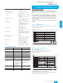
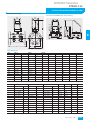
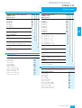
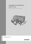
■ Overview
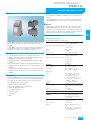
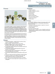
Siemens offers two types of ultrasonic flowmeters, wetted flowmeters and clamp-on flowmeters. This offers the end user the
maximum flexibility to choose the technology that best fits his
needs.
4
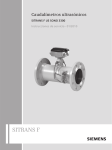
SITRANS F US SONOFLO wetted ultrasonic flowmeters measure
flow of electrically conductive and non-conductive liquids.
■ Application
Wetted ultrasonic flowmeters are suitable for measuring the flow
of almost all conductive and non-conductive liquids.
• max. 2% solids
• max. 2% air and gas
• max. 350 cSt
The main applications can be found in the following sectors:
• Raw water intake for water treatment plants
• Treated waste water
• Power generation and utility
• Oil and gas industry and petrochemical industry
• Irrigation systems
• Cooling water plants within the industry and in power stations
• Plants transporting non-conductive liquids
• HART / 4 ... 20 mA output
• PROFIBUS PA
• ATEX
■ Benefits
The SITRANS F US ultrasonic wetted flowmeters are used to
measure homogeneos conductive and non-conductive liquids.
• Sensor sizes from DN 50 to 1200 mm (2“ to 48“)
• Wetted retrofit as 1 and 2 track up to DN 4000 (160“)
• Dedicated transmitter portfolio for HVAC, general industry as
well as more demanding applications
• Custody transfer approvals within district heating
• Compact and remote transmitter installation
• Comprehensive self-diagnostic for error indication and logging
• Exchange of the transducers without interrupting operation
• HART and PROFIBUS PA communication
• ATEX
4/152
Siemens FI 01 · 2007
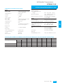
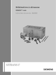
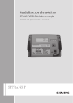
SITRANS F US clamp-on ultrasonic flowmeters provide highly
accurate measurement of liquids and gases while minimizing installation time and maintenance expense.
■ Application
Clamp-on ultrasonic flowmeters have six product families:
FUS1010 and FUP1010 General purpose flowmeters are suitable for a wide variety of liquid applications, including:
• Water and wastewater: raw water, potable water, sludges,
chemicals, raw sewage, effluent and mixed liquor
• HVAC: chillers, condensers, hot & cold water systems
• Power: nuclear, fossil, hydroelectric
• Processing: process control, batching, rate indication, volumetric and mass measurement
FUE1010 Energy flowmeters are ideally suited to thermal
energy/power industry applications, including:
• Chilled & hot water sub-metering
• Condenser water, potable water
• Glycol and brine solution, thermal storage
FUH1010 Hydrocarbon flowmeters are ideal for applications
carrying crude oil, refined petroleum or liquefied gas:
• Interface detectors / density meters
• Viscosity compensated volumetric flowmeters
• Standard volume (net) mass flowmeters
FUG1010 Gas flowmeters suit most natural and process gas applications, including: checkmetering, allocation, flow survey
verification, lost & unaccounted for (LAUF) analysis, production,
storage.
FUS1020 Basic flowmeters are suitable for many clean liquid
applications in the water & wastewater, chemical feed, HVAC
and power industries.
■ Benefits
• Easy installation; no need to cut pipe or stop flow
• Minimal maintenance; external transducers do not require
periodic cleaning - and no moving parts to wear or foul
• No pressure drop or energy loss - and wide turn-down ratio
• Single, dual or multiple channel versions and a variety of enclosures - to suit your operating conditions and requirements
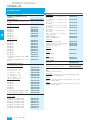
SITRANS F flowmeters
SITRANS F US
System info and selection guide
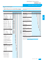
Ultrasonic flowmeters
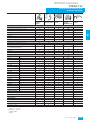
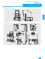
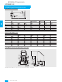
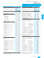
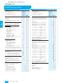
SONO
3300/3000
Industry
SONO 3100/
SONOKIT
FUS060 Industry retrofit
SITRANS
SITRANS
FUS880
FUS380/
SONOCAL 3000
Industry
Water, treated waste water,
●
●
■
Utility, district heating water, cooling
●
●
▲
■
■
Utillity, district heating, approvals required
Irrigation
●
●
▲
HPI, Oil & liquid gas
■
■
●
Chemical
●
●
Cryogenic fluids
●
Offshore, 2- and 4-track
▲
▲ 4)
■
4
Design
●
Pipe/electronic calibrated on test rig
●
●
Replaceable transducers under pressure
●
Retrofit on existing steel pipes/concrete/
non weldable pipes/hot tap
Compact
●
Separate
●
Transmitter type
●
●
SONO 3000
●
●
●
FUS060
●
FUS060
4)
●
FUS080
●
FUS080
Dimension
3)
DN 50
2"
●
●
DN 65
2½"
●
DN 80
3"
●
● 3)
3)
●
DN 100
4"
●
●
●
DN 125
5"
●
●
●
DN 150
6"
●
●
DN 200
8"
●
●
●
●
●
DN 225
9"
●
●
●
●
●
DN 250
10"
●
●
●
●
●
DN 300
12"
●
●
●
●
●
●
●
DN 350
14"
●
●
●
DN 400
16"
●
●
●
●
DN 500
20"
●
●
●
●
DN 600
24"
●
●
●
●
DN 700
28"
●
●
●
●
DN 800
32"
●
●
36"
●
●
DN 1000
40"
●
● 1)
●
●
● 3)
3)
●
● 3)
●
DN 900
●
●
DN 1200
48"
DN 4000 max.
160“
●
●
●
●
●
Number of tracks
●
1-track
2-track
●
4-track (on request)
●
●
●
●
●
Flanges Norm
EN 1092-1
●
●
EN 1759-1
●
●
●
ANSI B16.5
Flangeless version
●
1)
Bigger sizes on request
2)
FUS380: 87 ... 250 V AC
SONOCAL 3000
3)
4)
●
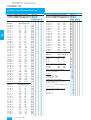
= can be used, ▲ = often used, ■ = most often used
FUS080
Siemens FI 01 · 2007
4/153
SITRANS F flowmeters
SITRANS F US
System info and selection guide
Ultrasonic flowmeters
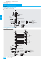
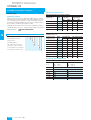
SONO
3300/3000
Industry
SONO 3100/
SONOKIT
FUS060 Industry retrofit
SITRANS
SITRANS
FUS880
FUS380/
SONOCAL 3000
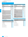
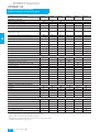
Pressure rating
PN 6
4
PN 10
●
PN 16
●
PN 25
●
●
●
●
●
●
3)
●
●
●
●
●
●
●
PN 40
●
●
Class 150
●
●
Class 300
●
●
●
PN 160
●
Class 2500
●
Pipe and flange material
●
Carbon steel
●
Stainless steel
●
Other materials on request
●
●
Hot zinc galvanised
Temperature range
°C
°F
-200
-330
-20
-4
●
●
-10
+14
●
●
●
0
+32
●
●
●
●
●
+50
+120
●
●
●
●
●
+120
+250
●
●
●
●
+160
+320
●
●
●
●
+200
+390
●
●
●
+250
+482
O
O
●
3)
Power supply
●
Battery
AC 115 … 230 V
●
●
●
DC 24 V
●
●
●
4)
●
● 2)
National approvals
●
● 4)
OIML R 75 (Heat meter approval)
EN 1434 class 2 (Heat meter approval)
●
Country specific type approval available
●
EEx-d
EEx ATEX
●
●
●
●
Others
Display with keypad
●
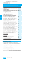
= can be used
O = special transducers
1)
Bigger sizes on request
2)
FUS380: 87 ... 250 V AC
SONOCAL 3000
3)
4)
FUS080
4/154
Siemens FI 01 · 2007
●
●
4)
●
SITRANS F flowmeters
SITRANS F US
System info and selection guide
Ultrasonic flowmeters
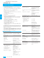
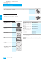
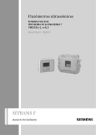
■ Function
Ultrasonic flow metering based on battery
Direct signal processing
In the SITRANS F US SONOFLO ultrasonic flowmeter program
the signal is sent directly and without deflection to the bore wall
from the transmitter to the receiver. The advantage gained sending signals from point to point is an extremely good signal
strength for the signal processing avoiding a suddenly flowmeter stop.
Siemens offers a solution based on a 3.6 V lithium cell battery
with a lifetime of up to 8 years. As the electronics is optimised to
operate at extremely low power consumption, the electronics is
limited in function and services. The battery powered ultrasonic
flowmeter finds its application mainly in power generation, utility
and irrigation where mains supply is out of reach.
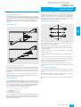
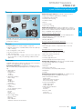
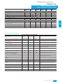
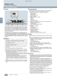
Pipe geometry with 2-track solution
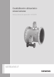
Physical principle
B
1
2
C
D
A
B
4
A
B
4
3
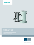
The accuracy of all flowmeters static or mechanical depends on
the pipe geometry before and after the flowmeter and the number of ultrasonic measuring tracks.
When water flows through a pipe, it has a tendency to swirl
and/or flow with different velocities inside the pipe, depending
on the pipe design.
Therefore 2-tracks or more is the most reliable technology today.
2-track systems offer
• less sensitivity to upstream obstruction like bends, pumps or
valves.
• high security in the measurements as the meter continues to
measure even if, for some reason, one track stops working.
A
Velocity distribution along sound path
Typical straight inlet requirements are upstream 10 x Di (Di = diameter of the flowmeter) and downstream 3 x Di.
Typical accuracy that can be reached with 2-track ultrasonic
flow metering is ±0.5% with installations according to above demands.
A sound wave traveling in the same direction as the liquid flow
arrives at point B from point A in a shorter time than the sound
wave traveling against the direction of flow (from point B to A).
The difference in sound transit time indicates the flow velocity in
the pipe.
4-track ultrasonic flowmeters
Since delay time is measured at short intervals both in and
against flow direction, viscosity and temperature have no influence on measurement accuracy.
For these applications we can offer a 4-track solution – customer
specified – according to actual inlet conditions.
Measuring principle
Some applications require accuracy under extreme short inlet
conditions and swirl that cannot be obtained with 2-track solutions.
Please contact Siemens Flow Instruments for specific applications.
In SITRANS F US SONOFLO flowmeters the two ultrasonic transducers are placed at an angle θ in relation to the pipe axis. The
transducers function as transmitters and receivers of the ultrasonic signals. Measurement is performed by determining the
time the ultrasonic signal takes to travel with and against the
flow. The principle can be expressed as follows:
v = K ⋅ (tA,B – tB,A) / (tA,B ⋅ tB,A) = K ⋅ ∆t/t²
v = Average flow velocity
t = Transit time
K = Proportional flow factor
This measuring principle offers the advantage that it is independent of variations in the actual sound velocity of the liquid, i.e. independent of the temperature. Proportional factor K is determined by wet calibration.
Siemens FI 01 · 2007
4/155
SITRANS F flowmeters
SITRANS F US
System info and selection guide
Ultrasonic flowmeters
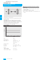
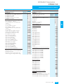
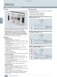
■ Technical specifications
MGD
(US)
m 3/h
l/min.
105
")
8
11
7")
500
(
00
15
0(
0
DN
50
20
100
10 4
50
50
20
20
10
10
DN
DN
0")
11
0(
0
28
4")
DN 00 (9
4
2
")
DN
79
0(
0
20
DN
")
63
0(
0
16
5")
DN 00 (5
4
1
")
DN
44
0(
10
1
DN
")
36
0(
0
9
DN
")
(28
00
7
DN
200
4
40
5
D
00
10
20
")
50
(71
10 5
")
59
0(
0
15
")
48
DN
0(
0
12
")
DN
(40
00
0
1
DN
")
(32
00
8
DN
00
50
20
105
(2
50
10 4
0
DN
")
DN
45
0
35
")
(18
500
")
20
")
10 4
(14
(
50
200
20
100
50
8"
0(
50
0
2
DN
)
(6"
10 3
1
DN
50
20
)
4"
0(
100
0.5
5")
DN
5(
2
N1
500
10
10 3
D
50
50
2
)
1
20
20
6
DN
DN
50
103
4")
3
DN
200
4
D
12
2
20
10
10
(
00
6
N1
1
D
500
2
0
80
6")
0(
0
N4
2")
(10
")
(87
0
60
D
2
0
N5
30
2
N2
0")
0(
3
GPM
(US)
l/s
20
200
0.2
DN
80
20
10
3")
500
(
100
5")
0.1
DN
6
0
N5
10
5
2.
5(
)
(2"
200
50
D
0.05
2
100
5
20
1
0.02
50
10
2
0.5
0.01
20
5
1
0.005
0.2
10
0.5
0.25 0.3
1 f/s
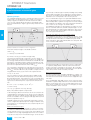
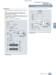
Nominal size and flow
4/156
Siemens FI 01 · 2007
1 m/s
0.5
1.5
2
1,5
5
2
10 m/s
5
10 f/s
15
20
33 f/s
SITRANS F flowmeters
SITRANS F US
System info and selection guide
Ultrasonic flowmeters
The sensor must always be completely filled with liquid.
Guidelines for selection of sensor
Min. measuring range: 0 … 0.25 m/s
Max. measuring range: 0 … 10 m/s
Normally the sensor is selected so that nominal flow velocity is
within the measuring range 3 … 5 m/s.
Flow velocity calculation formula:
!
v = (4 x Qmax ) / (π x Di² x 3600 )
v in m/s, Qmax in m³/h, Di in m
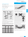
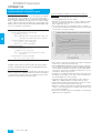
Inlet and outlet
4
Install in completely filled pipes
min. 10 x Di
min. 3 x Di
The following installations should be avoided:
• Installation at the highest point of the pipe system
• Installation in vertical pipes with free outlet
min. 20 x Di
min. 40 x Di
Recommended inlets and outlets
To maximize performance inlet and outlet must be straight. There
must be a certain distance between flowmeter and bends,
pumps and valves. It is also important to centre the flowmeter in
relation to pipe flanges and gaskets.
Valves must always be installed after the flowmeter. The only exception is installation of the sensor in a vertical pipe. In this case
a valve below the sensor is necessary to allow zero point adjustment. It is important to select a valve which does not alter the
flow when fully open.
Do not install at the highest point or in vertical pipes with free outlet
With partially full pipes or pipes with free outlet the flowmeter
should be located in a U-shaped tube.
Recommended inlet/outlet
SONO
3300/3100
SONOKIT
2-track
SONOCAL 3000 SONOKIT
1-track
2-track
SITRANS
FUS380
90° bend
10 x Di
10 x Di
20 x Di
Fully opened
valve
10 x Di
10 x Di
20 x Di
Partially opened 40 x Di
valve
40 x Di
40 x Di
2 x 90° bends in 15 x Di
same plane
10 x Di
25 x Di
2 x 90° bends in 20 x Di
two planes
20 x Di
40 x Di
Outlet
3 x Di
3 x Di
3 x Di
!
Install in U-shaped tube if pipe is partially filled
Installing the transducers in horizontal position is recommended.
Siemens FI 01 · 2007
4/157
SITRANS F flowmeters
SITRANS F US
System info and selection guide
Ultrasonic flowmeters
Additional effects of deviations from reference conditions
• Current output: As frequency output ±(0.1% of actual flow
+0.05% FSO)
• Effect of ambient temperature: Frequency/pulse output:
< 0.005% SPAN/K
• Current output: < ± 0.0075% SPAN/K
• Effect of supply voltage: 0.005% of measuring value at 1%
change
Install transducer in horizontal position
To ensure maximum accuracy sensor and transmitter must be
calibrated together.
SONO 3000 consists of an electronic device and a separate
SENSORPROM. Flowmeter calibration data are stored in the
SENSORPROM, and in the internal EPROM. The SENSORPROM
contains all necessary information for a quick startup.
The system accuracy refers to the following systems:
SONO 3300/3000, SONO 3100/FUS060.
Reference conditions
(UURU
4
9HORFLW\
PV
Fluid
Water
Fluid temperature
22 ± 5 °C
Ambient temperature
22 ± 5 °C
Supply voltage
AC 115/230 V +10 … -15%
DC 24 V +25 … -15%,
AC 24 V ± 15%
Straight inlet length
20 x Di
Rangeability
0 … 1 m/s to 0 … 10 m/s
Repeatabilty
Better than 0.25% in the range
0.5 … 10 m/s
Linearity
• Reynolds number
1000 < Re < 5000
Better than 1%
• Reynolds number > 5000
Better than 0.5%
4/158
Siemens FI 01 · 2007
SITRANS F flowmeters
SITRANS F US
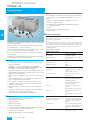
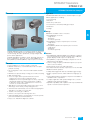
SONOFLO SONO 3000 transmitter
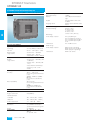
■ Overview
■ Design
The transmitter is available in 2 different enclosure to fit any demands:
• IP67 (NEMA 4X/6) enclosure for compact or wall mounting
• IP65 (NEMA 4) enclosure in stainless steel for EEx application
■ Function
Settings are stored automatically in the transmitter and in the
SENSORPROM flow memory unit. The values remain stored in
the event of power failure and when a transmitter is replaced.
Operation of any key illuminates the display. The light is automatically turned off 10 minutes after last key operation.
■ Technical specifications
SONO 3000 transmitter
Technical specifications for all versions
SONO 3000 is a transit time based transmitter designed for ultrasonic flowmetering on any pipe in the SONO series up to
DN 4000.
SONO 3000 is a microprocessor based transmitter engineered
for high performance, easy installation, commissioning and
maintenance, suitable for 1, 2 or 4 track flowmeters.
■ Benefits
•
•
•
•
•
•
•
•
Superior signal resolution for optimum turn down ratio
Unique correlation signal ensures realiable signal detection
Digital processing with many possibilities
Automatic reading of SENSORPROM data for easy commissioning
User configurable operation menu with password protection
Multiple functional output for process control, minimum configuration
Pulse/frequency and relay output (status, flow direction, limits)
Comprehensive self diagnostic for error indication and error
logging
■ Application
Analog output
Measurement of (optional via menu) Volume flow
Sound velocity
Current
0/4 … 20 mA
Load
< 800 Ω
Time constant
0.8 … 30 s, adjustable
Frequency/pulse output
Individually galvanically isolated,
isolation voltage 500 V
Measurement of (optional via menu) Volume flow
Sound velocity
Total volume
Total mass
Frequency
0 … 10 kHz
Time constant
0.8 … 30 s, adjustable
Pulse width
50 µs, 500 µs, 5 ms, 20 ms,
50 ms, 100 ms, 500 ms, 1 s, 5 s
Output mode
• Active
The SONO 3000 ultrasonic transmitter is suitable for processing
the flow of any conductive or nonconductive liquids with max.
2% solids, 2% air and gas and a viscosity of max. 350 cSt.
The main application can be found in:
• Water and waste water industries
• Chemical and pharmaceutical industries
• District heating applications
• Cooling water plants
• Oil and refinery
• Cryogenics
• Utility
Individually galvanically isolated,
isolation voltage 500 V
24 … 30 V DC / 25 mA max.
(pulse width : 50 µs … 5 s)
(50 ms electromechanical
counter, 75 mA max. if f < 1 Hz)
24 … 30 V DC / 50 mA max.
(f: 500 Hz … 10 kHz)
• Passive
5 ... 30 V DC / 200 mA max.
Relay
Change over relay (error indication, flow direction, sound velocity
limit)
Load
42 V, 0.5 A
Time constant / Hysteresis
5 s / 0.5% F.S.O.
Cut-off
Low Flow, 0 … 9.9% F.S.O.
Supply voltage and power consumption
115 … 230 V AC +10/-15%,
50 … 60 Hz, 10 … 20 VA
24 V DC +25/-15%, 24 V AC
± 15%, 10 VA
Internal counters (totalizers)
2, selectable uni- or bidirectional
counting (net flow)
Measurement of:
Total volume
Display
Back-lit, alphanumeric, 2 x 16
digit
For indication of: measured values, totalization, settings, error
codes and alarms
Siemens FI 01 · 2007
4/159
4
SITRANS F flowmeters
SITRANS F US
SONOFLO SONO 3000 transmitter
■ Technical specifications (continued)
SONO 3000 transmitter, IP67 (NEMA 4X/6)
SONO 3000 transmitter, EEx-d version, wall mounting
Enclosure IP67 (NEMA 4X/6) to IEC 60529 and DIN 40050
Enclosure EEx-d version, wall mounting
Material
Fibre glass reinforced polyamide
Separate mounted
Mechanical vibration
2 g, 1 … 800 Hz, sinusoidal in all
directions to IEC 68-2-6
IP65 (NEMA 4) to IEC 60529 and
DIN 40050
Material
AISI 316 and Duplex
Mechanical vibration
2 g, 1 … 800 Hz, sinusoidal in all
directions to IEC 68-2-6
4
Ambient temperature
• Operation
-20 …+55 °C (-4 … +131 °F)
• Storage
-40 … +85 °C (-40 … +185 °F)
Dimensions
See dimensional drawing
CE-mark
• EMC
Emission EN 61000-6-4
Immunity EN 61000-6-2
• Low voltage
According to EN 61010-1
Supply voltage and power consumption
115 … 230 V AC +10/-15%,
50 … 60 Hz, 10 … 20 VA
24 V DC +25/-15%, 24 V AC
± 15%, 10 VA
Cable impedance < 7 Ω at 24 V
Ambient temperature
• Operation
-20 … +55 °C (-4 … +131 °F)
• Storage
-40 … +85 °C (-40 … +185 °F)
Dimensions
See dimensional drawing
Weight
ca. 11 kg (24.25 lb)
Supply voltage and power consumption
24 V DC +25/-15%, 24 V AC
± 15%, 10 VA
Cable impedance < 10 Ω at 24 V
Description of Ex-approval
(no ATEX)
EEx de [ia/ib] II C T6
Flameproof Enclosure “d”
Outputs intrinsically safe class
“ia”
Display/keypad intrinsically safe
class “ib”
Power and sensor connections
are increased safe “e”
Separate version: DEMKO No.
94C.113341X
CE-mark
• EMC
Emission EN 61000-6-4
• Low voltage
According to EN 61010-1
Immunity EN 61000-6-2
Factory settings
Every transmitter is delivered with a SENSORPROM programmed with default settings according to flowmeter size.
The range for each setting is given. Detailed information see
Operating Manual.
4/160
Siemens FI 01 · 2007
SITRANS F flowmeters
SITRANS F US
SONOFLO SONO 3000 transmitter
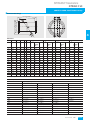
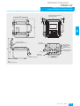
■ Dimensional drawings
Transmitter IP67 for wall mounting
8 (0.3)
71 (2.8)
12 (0.47)
8 (0.3)
13 (0.51)
240 (9.45)
154 (6.06)
105 (4.13)
10 (0.4)
13 (0.51)
71 (2.8)
4
170 (6.69)
190 (7.45)
Transmitter IP65 EEx-d
[
[
Siemens FI 01 · 2007
4/161
SITRANS F flowmeters
SITRANS F US
SONOFLO SONO 3000 transmitter
■ Schematics
Electrical diagram compact version IP67:
SONO 3000 IP67 compact mounted
4
P$
/RDG≤Ω
(UURU
)ORZGLUHFWLRQ
6RXQGOLPLW
5HOD\VKRZQLQGHHQHUJLVHGFRQGLWLRQ
3DVVLYH
$FWLYH
)UHT3XOVH
RXW
FRP
8
I
3DVVLYHH[WHUQDOVXSSO\
6HOHFWDEOHIUHTXHQF\RU
SXOVHRXWSXW
8 9GF
/RDG,PD[P$
3(
6XSSO\YROWDJH
$FWLYH9
6HOHFWDEOHIUHTXHQF\RU
SXOVHRXWSXW
)UHTXHQF\
PD[+]ORDG≥ Ω
PD[N+]ORDGNΩ
3XOVH
ORDG≥ Ω
RXW
FRP
3(
1
/
9DF
9DFGF
Electrical diagram remote version IP67:
SONO 3000 IP67 remote mounted
)ORZGLUHFWLRQ
8S
'RZQ
7UDQVGXFHU$
XSVWUHDP
7UDFN
/RZHUWUDFN
7UDQVGXFHU%
GRZQVWUHDP
7UDQVGXFHU&
XSVWUHDP
7UDFN
8SSHUWUDFN
(UURU
)ORZGLUHFWLRQ
6RXQGOLPLW
+
-
7UDQVGXFHU'
GRZQVWUHDP
P$
/RDG≤Ω
5HOD\VKRZQLQGHHQHUJLVHGFRQGLWLRQ
3DVVLYH
)UHT3XOVH
RXW
FRP
,
3(
6XSSO\YROWDJH
4/162
Siemens FI 01 · 2007
RXW
FRP
3(
1
/
Connect coax cable to 81, 83, 85 and 87.
$FWLYH
3DVVLYHH[WHUQDOVXSSO\
6HOHFWDEOHIUHTXHQF\RU
8 SXOVHRXWSXW
8 9GF
/RDG,PD[P$
9DF
9DFGF
$FWLYH9
6HOHFWDEOHIUHTXHQF\RU
SXOVHRXWSXW
)UHTXHQF\
PD[+]ORDG≥ Ω
PD[N+]ORDGNΩ
3XOVH
ORDG≥ Ω
SITRANS F flowmeters
SITRANS F US
SITRANS FUS060 transmitter
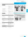
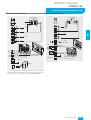
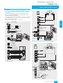
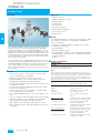
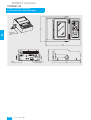
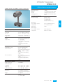
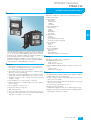
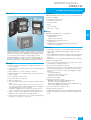
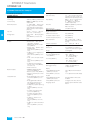
■ Overview
Displays and keypad
Operation of the SITRANS FUS060 transmitter can be carried out
using:
• Keypad and display unit
• HART communicator
• PC/laptop and SIMATIC PDM software via HART communication
• PC/laptop and SIMATIC PDM software using PROFIBUS PA
communication
Min. 230 W
Operating and
display panel
4
PC/
laptop
SITRANS FUS060 transmitter
SITRANS FUS060 is a transit time based transmitter designed
for ultrasonic flowmetering for any pipe in the SONO series up to
DN 4000. SITRANS FUS060 is engineered for high performance
and suitable for 1-, 2- and 4-tracks flowmeters.
■ Benefits
• Superior signal resolution for optimum turn down ratio
• Simple menu-based local operation with two-line display and
four optical input elements, for unlimited use in potentially explosive atmospheres
• Self-monitoring and diagnosis
• Operate up to 4-tracks
• ATEX II 2G EEx de IIC T6 (HART version only)
• ATEX II 2G EEx d [ia] IIC T6
• Remote transmitter up to 15 m away
• 1 analog output (4 to 20 mA) with HART-protocol, 1 digital frequency or pulse output, 1 relay output for limit, alarms, flow direction
• PROFIBUS PA Profile 2 add-on module, 1 digital frequency or
pulse output
■ Design
The transmitter is designed for remote installation in non-hazardous or hazardous areas.
HART
communicator
Coupling
module
RS-232
HART communication
PROFIBUS PA
PROFIBUS DP
Master
Bus
terminator
+
Coupler with
power supply
T
.......
Transmitter with
PROFIBUS PA interface
PROFIBUS PA communication
■ Function
The operating and display panel permits simple operation without supplementary equipment. It is not necessary to open the
housing. All changes to a setting can therefore also be carried
out in the potentially explosive atmosphere.
LCD
Optical
control element
Infrared
transmitter
Operating and display panel
The individual functions and parameters are selected using a hierarchical, multi-language input menu and four optical input
elements. The parameters can be specifically selected and
modified using codes, e.g.:
Siemens FI 01 · 2007
4/163
SITRANS F flowmeters
SITRANS F US
SITRANS FUS060 transmitter
4
• Operating parameters such as measuring range, physical dimensions, device information
• Limits for flow, ultrasonic velocity or ultrasonic amplitude
• Noise suppression using damping, error stages and hysteresis
• Display parameters (freely-configurable display)
• Display in volume or mass dimensions
• Density as constant input value for conversion of volume into
mass dimensions
• Forward/backward measurement
• Flow direction
• Diagnostics functions and control values
• Functions of the PROFIBUS PA output:
flow, net quantity (volume or mass), speed of sound, ultrasonic
amplitude, forward quantity (volume or mass), backward
quantity (volume or mass)
• Functions of the analog output:
flow, ultrasonic velocity or ultrasonic amplitude
• Functions of digital output 1:
pulse output, frequency output or device status
• Functions of digital output 2:
limit, flow direction or device status
• Simulation of output signal via analog output, digital output 1
and digital output 2
The HART protocol is implemented via the analog output (current output). Using this communication facility, the device can be
parameterized with a PC/laptop and SIMATIC PDM software in
addition to local operation.
In the SITRANS F version with PROFIBUS PA, the analog output
is replaced by the digital PROFIBUS PA output. The device can
then be parameterized via PROFIBUS communication and with
SIMATIC PDM in addition to local operation.
■ Technical specifications
Input
Nominal diameters and measuring
ranges
2-track DN 50 ... DN 4000
Max. cable length
15 m (49.2 ft) (screened cable)
• Relay, NC or NO contact
Switching capacity max. 5 W
Max. DC 50 V, max. DC 200 mA
Self-resetting fuse,
Ri = 9 Ω
• For explosion protection II 2G EEx
d [ib]
Max. DC 30 V, max DC 100 mA,
AC 50 mA (cf. EC-Type Examination certificate)
• Output function, configurable
Limit for
Flow, speed of sound or ultrasonic amplitude
Flow direction
Device status
Digital output 2 omitted
• Only PROFIBUS PA version:
Communication via
analog output 4 ... 20 mA
• PC/laptop or HART communicator
with SITRANS F flowmeter
- Load with connection of
coupling module
230 ... 500 Ω
- Load with connection of
HART communicator
230 ... 600 Ω
- Cable
2-wire screened
≤ 3 km (≤ 1.86 miles)
Multi-core screened
≤ 1.5 km (≤ 0.93 miles)
- Protocol
HART, version 5.1
Communication via
PROFIBUS PA interface
Layers 1 + 2 according to
PROFIBUS PA
Communication system according to IEC 1158-2
Layer 7 (protocol layer) according
to PROFIBUS DP, EN 50170 standard
• Power supply
Separate supply, four-wire device
Permissible bus voltage 9 ... 32 V
See certificates and approvals
• Current consumption from bus
10 mA; ≤15 mA in event of error
with electronic current limiting
Electrical isolation
Outputs electrically isolated from
power supply and from one
another
Accuracy
Output
Analog output
• Signal range
4 ... 20 mA
• Upper limit
20 ... 22.5 mA, adjustable
• Signal on alarm
3.6 mA, 22 mA, or 24 mA
• Load
Max. 600 Ω;
≥ 230 Ω for HART communication
• Only PROFIBUS PA version:
Analog output omitted, is
replaced by digital PROFIBUS PA
interface
Digital output 1
• Active or passive signal,
can be configured with positive
or negative logic
Active: DC 24 V, ≤ 24 mA,
Ri = 300 Ω
Passive: open collector,
DC 30 V, ≤ 200 mA
• For explosion protection
II 2G EEx dem [ib]
Passive: open collector
DC 30 V, ≤ 100 mA
• Only PROFIBUS PA version:
Only passive signals for digital
output 1
• Output function, configurable
Pulse output
• Adjustable pulse significance
≤ 5,000 pulses/s
• Adjustable pulse width
≥ 0.1 ms
Frequency response
• fEND selectable up to 10 kHz
4/164
Digital output 2
Siemens FI 01 · 2007
Error in measurement
(at reference conditions)
• Pulse output
V < 0.5 m/s: ± 0.25%
• Analog output
As pulse output plus ± 0.1% of
measured value, ± 20 µA
• Repeatability
≤ ± 0.05% of measured value
Reference conditions
• Process temperature
25 °C ± 5 °C (77 °F ± 9 °F)
• Ambient temperature
25 °C ± 5 °C (77 °F ± 9 °F)
• Warming-up time
30 min.
SITRANS F flowmeters
SITRANS F US
SITRANS FUS060 transmitter
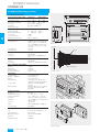
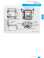
■ Dimensional drawings
Rated operation conditions
Ambient conditions
Ambient temperature
• -20 ... +65 °C (-4 ... +149 °F)
with process temp. ≤ 60 °C
(≤ 140 °F)
• -20 ... +55 °C (-4 ... +131 °F)
with process temp. > 60 °C
(> 140 °F)
• For operating panel
0 ... 50 °C (32 ... 122 °F)
• In potentially explosive
atmospheres
Observe temperature classes
Storage temperature
-25 ... +80 °C (-13 ... +176 °F)
Degree of protection
IP65
Electromagnetic compatibility
For use in industrial environments
• Emitted interference
To EN 61000-6-4
• Noise immunity
To EN 61000-6-2 and NAMUR
Medium conditions
• Process temperature
-20 ... +180° C (-4 ... +356 °F)
• Gases/solids
Influence accuracy of measurement
Design
Transmitter
• Separate version
• Housing material
Transmitter is connected to
metering tube via 15 m (49.2 ft)
long specially screened cable
Die-cast aluminum
Electrical connection
Cable inlet: 2x M20 or 2x ½“-NPT
Displays and controls
Display
• Multi-display:
2 freely-selectable values are displayed simultaneously in two lines
Operation
Power supply
Supply voltage
LCD, two lines with 16 characters
each
Flow, quantity, flow velocity,
speed of sound, ultrasonic amplitude, current, frequency
4 optical control elements
Hierarchical menu prompting with
codes
• Power consumption
AC 120 ... 230 V ± 15%
(50/60 Hz) or DC 19 ... 30 V/
AC 20.4 ... 26.4 V
No effect for at least 1 period
(> 20 ms)
Approx. 8 VA / 6 W
Certificates and approvals
Explosion protection
• ATEX version w. HART
II 2G EEx de IIC T6
• ATEX version w. PROFIBUS PA
II 2G EEx d [ia] IIC T6
• Power failure
• For transmitter
4
SITRANS FUS060, dimensions in mm (inch)
■ Schematics
(DUWKFRQQHFWLRQIRUVLJQDOFDEOHVFUHHQ
'LJLWDORXWSXWUHOD\V
RQO\IRU+$57
'LJLWDORXWSXWDFWLYHSDVVLYH
$QDORJRXWSXWDFWLYHWRP$ RU352),%86
3RZHUVXSSO\ /1IRU$&WR9
//IRU8&9
(DUWKWHUPLQDOIRU3(
3
4
5
+
6
–
7
+
8
–
20 mA
1 2
L N
L+ L–
SITRANS FUS060
Siemens FI 01 · 2007
4/165
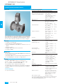
SITRANS F flowmeters
SITRANS F US
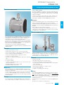
SONOFLO SONO 3300/3000 Industry
■ Overview
■ Technical specifications
2-track sensor with flanges and integrated transducers
Error in measurement
Error in measurement at reference
conditions; % of measured value
v>0.5...10m/s, <± 0.5% of rate
(v=flow speed)
SONO 3300 DN 50 and DN 65:
For Reynolds numbers
1000 < Re < 5000: ± 1.5%
4
Max. flow velocity
10 m/s (32 ft/s)
Nominal size
DN 50, DN 65, DN 80, DN 100,
DN 125, DN 150, DN 200
(2” … 8”)
DN 250, DN 300 (10” … 12”)
Liquid temperature
Separate version: -10 … +160 °C
(14 … 320 °F)
Compact version: -10 … +120 °C
(14 … 248 °F)
Compact EEx d: -10 … 160 °C
(14 … 320 °F)
Ambient temperature
Separate version: -40 … +160 °C
(-40 … +320 °F)
Compact version: -20 … +55 °C
(-4 … +131 °F)
The combination of sensor SONO 3300 sensor and SONO 3000
transmitter is ideal for applications within the general industry.
Measurements are independent of liquid temperature, density,
pressure and conductivity. Transducers cannot be changed.
Storage: -40 … +85 °C
(-40 … 185 °F)
Enclosure
Standard version: IP67
(NEMA 4X/6)
Process connections
■ Benefits
• Compact / remote design
• Robust design for industrial applications
• Measures all liquids less than 350 cSt, conductive or non conductive
• No pressure drop
• Reliable and accurate flow measurements
• Long time stability
■ Application
The main application for SONO 3300 / 3000 ultrasonic flowmeter
is measurement of volume.
SONO 3300 / 3000 can be used for water and treated waste water, oil and liquid gases, hot water / cooling systems.
PN designated
EN 1092-1-type 11,B
• DN 50 ... DN 300 (2” … 12”),
PN 40
• DN 100 ... DN 300 (4” … 12”),
PN 16
• DN 200 ... DN 300 (8” … 12”),
PN 10
Class designated
EN 1759-1-type 11,B
• DN 125 ... DN 300 (5” ... 12”),
class 150
• DN 50 ... DN 300 (2” ... 12”),
class 300
Transducer
Integrated version welded into
pipe
Materials
Pipe
• DN 50 ... DN 150 (2” … 6”):
Steel EN 1.113145-16Mn5
• DN 200 ... DN 300 (8” … 12”):
Steel EN 1.0345-P235GH
■ Design
The SONO 3300 / 3000 consists of a casted sensor
(DN 50 ... 150 (2” … 6”)), welded pipes (DN 200 … 300
(8” … 12”)) and the transmitter SONO 3000.
The transmitter can be compact or wall mounted.
The signal cables from transducers to transmitter are highly protected from aggressive environment by protection of stainless
steel pipes.
Flange
• DN 50 ... DN 300 (2” … 12”):
EN 1.0025-S235JRG2
Class
ASTM A105
Transducer
Stainless steel AISI 316 or similar
Certificates and approvals
Ex approval sensor
• Ex version: Compact EEx de
[ia/ib] IIC T5-T6, no ATEX
• Ex version: Separate EEx de IIC
T3-T6, no ATEX
Material certificate
The sensor is supplied as standard with a Siemens Flow Instruments certificate of conformity.
Material certificate on wetted
parts on request
NDT examination report
Available on request
Sensor installation
See system information
The sensors are approved according to EU directive 97/23EF dated 29
May 1997 regarding fluid group 1, classified in category III. Design
according to EN 13480 (PED Directive).
4/166
Siemens FI 01 · 2007
SITRANS F flowmeters
SITRANS F US
SONOFLO SONO 3300/3000 Industry
Coaxial cable between sensor and transmitter
Coaxial cable (75 Ω) for SONO 3300/3000
1 x Ø 0.8 mm (0.03”) copper conductor with
shield
Diameter
5.8 mm (0.23”)
Length
Max. 250 m (820 ft)
between sensor and
transmitter
Material (outside
jacket)
Black PE
Ambient temperature
-10 … +75 °C
(+14 ... +167 °F)
1 x Ø 0.65 mm (0.026“) copper conductor with
shield
Diameter
5.3 mm (0.21“)
Length
Max. 100 m (328 ft)
between sensor and
transmitter
Material (outside
jacket)
Brown FEP (Teflon)
Ambient temperature
-200 … +200 °C
(-328 ... +392 °F)
4
Siemens FI 01 · 2007
4/167
SITRANS F flowmeters
SITRANS F US
SONOFLO SONO 3300/3000 Industry
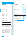
Standard FDK number available
All 2-track, painted steel, flanges, AISI 316 transducers, wet calibrated.
Sensor
Certifienclosure cates
IP67 1)
standard
4
Pressure
Certificate PN 10
of conforPN 16
mity
PN 40
Material
certificate
Size
DN 50
DN 65
DN 80
DN 100
DN 125
DN 150
DN 200
DN 250
DN 300
FDK-
FDK-
FDK-
FDK-
FDK-
FDK-
FDK-
FDK-
FDK-
085L3020
085L3025
085L3030
085L3125
085L3012
085L3013
085L3014
085L3021
085L3026
085L3031
085L3002
085L3003
085L3004
085L3005
085L3022
085L3027
085L3032
085L3182
085L3131
085L3015
085L3016
085L3023
085L3028
085L3033
085L3008
085L3009
085L3010
085L3011
085L3024
085L3029
085L3034
085L3140
085L3116
085L3135
085L3136
085L3134
085L3129
085L3145
085L3122
085L3146
085L3132
085L3000
ANSI
class 150
085L3121
ANSI
class 300
085L3006
085L3001
085L3007
PN 10
085L3174
PN 16
PN 40
085L3141
085L3128
ANSI
class 150
085L3179
085L3161
ANSI
class 300
PN 16
Material
certificate
+ welding PN 40
inspection ANSI
class 150
085L3149
085L3150
085L3151
085L3152
085L3163
085L3130
085L3153
085L3154
Material
certificate
085L3166
085L3165
085L3120
085L3155
085L3138
085L3158
085L3123
2)
Certificate PN 10
IP67 ,
EEx de IIC of conforPN 16
mity
T3-T6,
no ATEX
PN 40
085L3171
085L3144
085L3080
ANSI
class 150
085L3156
ANSI
class 300
085L3086
085L3081
085L3087
085L3105
085L3110
085L3137
085L3092
085L3093
085L3094
085L3101
085L3106
085L3111
085L3082
085L3083
085L3084
085L3085
085L3102
085L3107
085L3112
085L3178
085L3139
085L3095
085L3096
085L3103
085L3108
085L3113
085L3088
085L3089
085L3090
085L3091
085L3104
085L3109
085L3114
PN 16
085L3126
PN 40
085L3100
085L3118
085L3169
085L3160
ANSI
class 150
085L3177
ANSI
class 300
085L3147
085L3168
ANSI
Material
certificate class 300
+ welding
inspection
IP67 3),
EEx de
[ia/ib] IIC
T5-T6,
no ATEX
Certificate PN 10
of conforPN 16
mity
PN 40
Material
certificate
085L3127
085L3060
085L3065
085L3070
085L3164
085L3052
085L3053
085L3054
085L3061
085L3066
085L3071
085L3040
085L3041
085L3042
085L3043
085L3044
085L3045
085L3062
085L3067
085L3072
ANSI
class 150
085L3124
085L3119
085L3142
085L3143
085L3055
085L3056
085L3063
085L3068
085L3073
ANSI
class 300
085L3046
085L3047
085L3048
085L3049
085L3050
085L3051
085L3064
085L3069
085L3074
PN 40
ANSI
class 150
085L3115
085L3173
085L3172
ANSI
class 300
PN 40
Material
certificate
+ welding
inspection
1)
2)
3)
085L3175
085L3159
085L3176
085L3180
085L3170
Transmitter SONO 3000 IP67(NEMA 4X/ 6) can be mounted compact, other transmitter remote mounted.
Transmitter, cables and IP67 (NEMA 4X/6) wall mounting kit have to be ordered separately
Transmitter SONO 3000 remote mounted in safe area or SONO 3000 Ex d wall mounted
Transmitter, cables and IP67 (NEMA 4X/6) wall mounting kit have to be ordered separately
Transmitter SONO 3000 Ex d inclusive and compact mounted on the sensor
4/168
Siemens FI 01 · 2007
085L3167
085L3181
085L3157
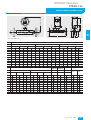
SITRANS F flowmeters
SITRANS F US
SONOFLO SONO 3300/3000 Industry
■ Dimensional drawings
/
'L
'
$
S
A/
LO R
R e g . b y S I MEN S
A3
SONO 3000
SO
NO
F
$
SITRANS F US SONOFLO
4
SONO 3300/3000 industry
DN
DIN 2632 / DIN 2633 / DIN 2635
PN 10
PN 16
L
mm
D
inch
mm
inch
mm
PN 40
L
Di
inch
D
mm
inch
Di
mm
inch
mm
L
inch
50
65
80
380
14.96
200
7.87
78.00
3.07
D
Di
mm
inch
mm
inch
mm
inch
475
18.70
165
6.50
52.60
2.07
475
18.70
185
7.28
62.70
2.47
400
15.75
200
7.87
78.00
3.07
100
355
14.72
220
8.66
102.40 4.00
400
15.75
235
9.25
102.40 4.00
125
375
14.72
250
9.84
128.30 5.05
400
15.75
270
10.63
128.30 5.05
154.20 6.07
150
360
14.17
285
11.22
154.20 6.07
400
15.75
300
11.81
200
400
15.75
340
13.39
207.30 8.16
400
15.75
340
13.39
207.30 8.16
450
17.72
375
14.76
206.50 8.13
250
400
15.75
395
15.55
260.40 10.25
400
15.75
405
15.94
260.40 10.25
500
19.69
450
17.72
258.80 10.19
300
400
15.75
445
17.52
309.70 12.19
420
16.54
460
18.11
309.70 12.19
500
19.69
515
20.28
307.90 12.12
DN ANSI
Weight 1)
without
with
SONO 3000 SONO 3000
150 Ib
300 Ib
L
D
Di
L
D
Di
A
A1
A3
DIN
(PN 40)
ANSI
CL 300
mm inch
mm inch
mm
inch
mm inch
mm inch
mm
inch
mm inch
mm inch
mm inch
kg
lbs
kg
lbs
50
510 20.08
152 5.98
52.6
2.07
520 20.47
165 6.50
52.6
2.07
180 7.09
272 10.71
234 9.21
14
30.9
17
37.5
65
510 20.08
178 7.01
62.7
2.47
520 20.47
190 7.48
62.7
2.47
186 7.32
278 10.94
240 9.45
16
35.3
20
44
80
420 16.54
191 7.52
78.0
3.07
440 17.32
210 8.27
78.0
3.07
193 7.60
283 11.14
245 9.65
19
42
23
51
100 420 16.54
229 9.01
102.4 4.03
440 17.32
254 10
102.4 4.03
205 8.07
297 11.69
259 10.20
25
55
35
78
125 440 17.32
254 10.00
128.3 5.05
460 18.11
279 10.98
128.3 5.05
218 8.58
310 12.20
272 10.71
29
64
40
89
150 430 16.93
279 10.98
154.2 6.07
450 17.71
318 12.52
154.2 6.07
232 9.13
324 12.76
286 11.26
35
78
50
111
200 480 18.90
343 13.50
202.7 7.98
500 19.69
381 15
202.7 7.98
256 10.08
348 13.70
310 12.20
54
119
72
160
250 490 19.29
406 15.98
254.5 10.02
520 20.47
444 17.48
254.5 10.03
283 11.14
375 14.76
337 13.27
85
189
98
217
300 550 21.65
483 19.02
306.3 12.06
580 22.83
521 20.51
306.3 12.06
309 12.17
401 15.79
363 14.49
115 256
1)
142 322
When mounting the transmitter, the weight increases by 2 kg (4.4 lb), with the EEx transmitter, the weight increases by 10 kg (48.5 lb).
Siemens FI 01 · 2007
4/169
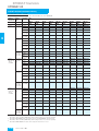
SITRANS F flowmeters
SITRANS F US
SONOFLO SONO 3100/FUS060 Industry
■ Overview
■ Technical specifications
2-track sensor fitted with four SONO 3200 transducers
Error in measurement
Error in measurement at reference
conditions; % of measured value
v>0.5...10m/s, <± 0.5% of rate
(v=flow speed)
Max flow velocity
10 m/s (32 ft)
Nominal size
DN 100 ... DN 1200 (4” ... 48”)
Liquid temperature
-10 °C ... +200 °C (14 ... 392 °F)
Ambient temperature
-20 °C ... +200 °C (-4 ... +392 °F)
Enclosure
IP68 (NEMA 6)
Process connections
4
PN designated, EN 1092-1-type II, B
The SONO 3100 sensor and the FUS060 transmitter is an ideal
combination for applications where process shut down is impossible during service and where there is a need for extreme
high/low temperatures and pressures.
Transducers can easily be changed without interrupting operation. SONO 3100 can be delivered in 4-track solution for absolute best performance and accuracy.
■ Benefits
• Replaceable transducers under pressure
• Measure on all liquids less than 350 Cst, conductive or non
conductive
• No pressure drop
• Reliable and accurate flow measurements
• Long time stability
• On request:
- Special sensor material, e.g. Duplex
- High/low temperature sensor version: +250 °C (+482 °F) /
-200 °C (-382 °F) sensors
- Pressure rating 430 bar (6235 psi)
- 4 track sensor technology
■ Application
Pipe material carbon steel
• DN 200 ... DN 1200 (8” ... 48”)
PN 10
• DN 100 … DN 1200 (4” … 48”)
PN 16
• DN 200 … DN 1000 (8” … 40”)
PN 25
• DN 100 … DN 500 (4” … 20”)
PN 40
Pipe material stainless steel
• DN 200 … DN 300 (8” … 12”)
PN 10 and PN 25
• DN 100 … DN 300 (4” … 12”)
PN 16 and PN 40
Class designated, EN 1759-1-type II, B
Pipe material carbon steel
• DN 100 … DN 600 (4” … 24”)
Class 150
• DN 100 … DN 300 (4” … 12”)
Class 300
Pipe material stainless steel
• DN 100 … DN 300 (4” … 12”)
Class 150 and Class 300
Without flanges,
only in carbon steel
• DN 100 … DN 1200 (4” … 48”)
PN 16
• DN 200 … DN 1000 (8” … 40”)
PN 25
• DN 100 … DN 500 (4” … 20”)
PN 40
Transducer SONO 3200
O-ring or flange versions
2-track sensor fitted with four SONO 3200 transducers
Materials
Pipe
Steel EN 1.0345-P235GH or
stainless steel EN 1.4404 AISI 316L
Flange
The main application for SONO 3100 in combination with
FUS060 ultrasonic flowmeter is to measure volume within.
• Petrochemical industry
• Power engineering
• Water and waste water
• Oil and liquid gases
PN
EN 10025-S235JRG2, 1E1 or
stainless steel EN 10222-51.4404, 13E0
Class
ASTM A105,1,1 or stainless steel
ASTM F316L,2,3
Transducer body
Stainless steel AISI 316 or similar
SITRANS FUS060 holds ATEX for hazardous areas, HART and
PROFIBUS PA. SONO 3100 holds ATEX Ex approval.
Transducer terminal house
Stainless steel AISI 316 or plastic
PA 6.6
Certificates and approvals
■ Design
Ex approval sensor
The SONO 3100 in combination with FUS060 consists of a
SONO 3100 sensor, transducers with O-rings or flanges depending on selection - and a FUS060 transmitter.
SONO 3100 is basically supplied in a 2-track solution with and
without flanges in sizes from DN 100 to DN 1200.
4 track version is avaible on request.
SONO 3100 is as standard available in carbon/stainless steel
from DN 100 to DN 1200.
FUS060 is designed for wall mounting only.
4/170
Siemens FI 01 · 2007
Material certificates
NDT examination report
ATEX
EEx i IIC T3
The sensor is supplied as standard with a Siemens Certificate of
Conformity.
Material certificate on wetted
parts on request.
Available on request
The sensors are approved according to EU directive 97/23/EF, dated 29
May 1997, regarding fluid group 1, classified in category III. Design
EN 13480 (PED directive)
SITRANS F flowmeters
SITRANS F US
SONOFLO SONO 3100/FUS060 Industry
Selection and Ordering data
Order-No.
SITRANS F US SONO 3100 sensor
2-track
7 ME 3 1 0 0 -
Order code
7 77 7 7 - 7 7 7 7 7 7 7
Selection and Ordering data
Order-No.
SITRANS F US SONO 3100 sensor
2-track
7 ME 3 1 0 0 -
Order code
7 77 7 7 - 7 7 7 7 7 7 7
Diameter
Qn [m3/h]
DN 100 / 4"
DN 100 / 4"
DN 100 / 4"
28
100
220
1N
1P
1R
Carbon steel
Stainless steel
DN 125 / 5"
DN 125 / 5"
DN 125 / 5"
44
150
350
1S
1T
1V
IP67 (NEMA 4X/6) PA housing, PN 40,
O-ring, 50 mm, 100 °C (212 °F)
1
64
220
500
2A
2B
2D
IP68 SS housing, PN 40, O-ring, 50 mm,
200 °C (392 °F)
2
DN 150 / 6"
DN 150 / 6"
DN 150 / 6"
4
DN 200 / 8"
DN 200 / 8"
DN 200 / 8"
110
380
900
2E
2F
2H
DN 250 / 10"
DN 250 / 10"
DN 250 / 10"
180
600
1300
2J
2K
2M
DN 300 / 12"
DN 300 / 12"
DN 300 / 12"
250
850
2000
2N
2P
2R
IP67 (NEMA 4X/6) PA housing, PN 40,
flange, 88 mm, 100 °C (212 °F)
IP68 SS housing, PN 40, flange, 88 mm,
200 °C (392 °F)
IP68 SS housing, PN 40, O-ring, 50 mm,
190 °C (374 °F), EEx i IIC T3, M20 gland,
ATEX approval
IP68 SS housing, PN 40, flange, 88 mm,
190 °C (374 °F), EEx i IIC T3, M20 gland,
ATEX approval
DN 350 / 14"
DN 350 / 14"
DN 350 / 14"
350
1000
2800
2S
2T
2V
DN 400 / 16"
DN 400 / 16"
DN 400 / 16"
450
1300
3600
3A
3B
3D
DN 500 / 20"
DN 500 / 20"
DN 500 / 20"
1300
2200
4200
3J
3K
3M
DN 600 / 24"
DN 600 / 24"
DN 600 / 24"
1300
3200
4200
3S
3T
3V
DN 700 / 28"
DN 700 / 28"
DN 800 / 32"
2000
4200
4200
4E
4F
4N
DN 800 / 32"
DN 900 / 36"
DN 900 / 36"
5500
4200
7500
4P
5A
5B
DN 1000 / 40"
DN 1000 / 40"
DN 1200 / 48"
DN 1200 / 48"
4200
9000
4200
13200
5J
5K
5S
5T
Pipe and flange material
1
2
Transducer type and approval
Cable gland entires
Cable glands M20 in transducers and in
transmitter M25/20/16 x 1.5
Cable glands ½“ NPT in transducers and in
transmitter
4
5
7
8
1
2
Transmitter SITRANS FUS060
IP65 (NEMA 4), 120/230 V AC
IP65 (NEMA 4), 24 V AC/DC
IP65 (NEMA 4), 24 V AC/DC ATEX Ex-d
Module
HART, 1 pulse output, 1 relay
HART EEx e, 1 pulse output, 1 relay
N
P
Q
B
C
D
E
PROFIBUS PA,1 pulse/frequency
PROFIBUS PA, EEx [ia],
1 pulse/frequency
Transducer coax cable
4 x 3 meter, max. 70 °C (158 °F)
4 x 15 meter, max. 70 °C (158 °F)
Teflon cable 4 x 3 meter, max. 200 °C
(392 °F)
Teflon cable 4 x 15 meter, max. 200 °C
(392 °F)
0
1
7
8
Please also see www.siemens.com/SITRANSFordering
for practical examples of ordering
Flange norm and pressure rating
(All sizes are not available in all pressure ratings)
EN 1092-1
PN 10
PN 16
PN 25
PN 40
B
C
D
E
ANSI B16.5
class 150
class 300
H
J
pipe without flanges
PN 10
PN 16
PN 25
PN 40
P
Q
R
S
Siemens FI 01 · 2007
4/171
SITRANS F flowmeters
SITRANS F US
SONOFLO SONO 3100/FUS060 Industry
Selection and Ordering data
Order code
Additional information
Please add „-Z“ to Order No. and specify Order code(s)
and plain text.
Calibration
4
Production calibration DN 100 ... DN 1200
Theoritical calibration DN 500 ... DN 1200
Included
D03
Match pair calibration 2 x 3 points
Max. flow 250 ... 1300 m3/h depending on dimension
(DN 100 ... DN 500)
D06
Match pair calibration 2 x 3 points
Max. flow 1400 ... 4200 m3/h depending on dimension
(DN 300 ... DN 700)
Match pair calibration 2 x 3 points
Max. flow 4200 m3/h depending on dimension
(DN 800 ... DN 1200)
D07
Accredited Siemens ISO/IEC 17025 calibration
Max. flow 250 ... 1300 m3/h depending on dimension
(DN 100 ... DN 500)
D21
Accredited Siemens ISO/IEC 17025 calibration
Max. flow 1400 ... 4200 m3/h depending on dimension
(DN 300 ... DN 700)
D22
Accredited Siemens ISO/IEC 17025 calibration
Max. flow 4200 m3/h depending on dimension
(DN 800 ... DN 1200)
D23
Accredited - Third party ISO/IEC 17025 calibration
Max. flow 250...1300 m3/h depending on dimension
(DN 100 ... DN 500)
D31
Accredited - Third party ISO/IEC 17025 calibration
Max. flow 1400...4200 m3/h depending on dimension
(DN 300 ... DN 700)
D32
Accredited - Third party ISO/IEC 17025 calibration
Max. flow 4300...7000 m3/h depending on dimension
(DN 800 ... DN 1200)
D33
EN 10204-3.1.B
EN 10204-3.1.B and 100% NDT on weldings,
DN 100 ... DN 400
EN 10204-3.1.B and 100% NDT on weldings,
DN 500 ... DN 700
EN 10204-3.1.B and 100% NDT on weldings,
DN 800 ... DN 1200
F10
F11
D08
F12
F13
Pressure certificate
EN 10204-2.3
F21
Tag name plate
Stainless steel tag with 12 mm characters,
max. 15 characters (add plain text)
Self-adhesive plastic tag with 8 mm characters, max.
15 characters (add plain text)
Y17
Y18
Please also see www.siemens.com/SITRANSFordering
for practical examples of ordering
4/172
Siemens FI 01 · 2007
SITRANS F flowmeters
SITRANS F US
SONOFLO SONO 3100/FUS060 Industry
■ Dimensional drawings
%
''
'X
/////
/
+
Θ
4
$
EN 1092-1
DN
DU
PN10
PN16
PN25
L
B
q
H
L10
W101) D10
Flange
dla.
L16
W161) D16
Flange
dla.
W251)
D25
Flange
dla.
L25
PN40
W401)
L40
D40
Flange
dla.
[mm]
[mm]
[mm]
[°]
[mm]
[mm]
[mm]
[mm]
[mm]
[mm]
[mm]
[mm]
[mm]
[mm]
[mm]
[mm]
[mm]
100
114.3
860
305
30
48.2
3.6
220
960
3.6
220
960
3.6
235
990
3.6
235
990
125
139.7
862
325
30
59.3
4.0
250
970
4.0
250
970
4.0
270
990
4.0
270
990
150
168.3
862
350
30
71.7
4.5
285
970
4.5
285
970
4.5
300
1010
4.5
300
1010
200
219.1
668
430
45
92.9
6.3
340
790
6.3
340
790
6.3
360
820
6.3
375
840
250
273.0
714
480
45
117.2
6.3
395
850
6.3
405
850
7.1
425
890
7.1
450
920
300
323.9
607
525
45
139.4
7.1
445
740
7.1
460
760
8.0
485
790
8.0
515
830
350
355.6
639
550
45
152.8
8.0
405
770
8.0
520
800
8.0
555
840
8.8
580
880
400
406.4
703
600
45
175.7
8.0
565
850
8.0
580
875
8.8
620
925
11.1
660
975
500
508.0
797
690
45
222.2
7.1
670
950
8.0
715
980
10.0
730
1050
14.2
755
1080
600
610.0
912
705
60
268.1
7.1
780
1075
8.8
840
1105
11.0
845
1165
-
-
-
700
711.0
937
895
60
312.8
8.0
895
1100
8.8
910
1140
12.5
960
1190
-
-
-
800
813.0
967
985
60
358.7
8.0
1015
1150
10.0
1025
1180
14.2
1085
1240
-
-
-
900
914.0
1007
1070
60
402.3
10.0
1115
1200
10.0
1125
1230
16.0
1185
1300
-
-
-
1000
1016.0
1060
1160
60
448.2
10.0
1230
1250
10.0
1255
1300
17.5
1320
1370
-
-
-
1200
1220.0
1100
1350
60
539.1
11.0
1455
1330
12.5
1485
1360
-
-
-
-
-
-
1)
Wall thickness
SONO 3100, 2-track
Nominal diam.
Weight [kg] ([lbs])
DN
PN 10
PN 16
PN 25
PN 40
100
32 (70.5)
32 (70.5)
35 (77.2)
35 (77.2)
125
38 (83.8)
38 (83.8)
44 (97.0)
44 (97.0)
150
45 (99.2)
45 (99.2)
52 (114.6)
52 (114.6)
200
59 (130.0)
58 (127.9)
70 (154.3)
79 (174.2)
250
73 (161.0)
75 (163.3)
96 (211.6)
117 (257.9)
300
83 (183.0)
92 (202.8)
114 (251.3)
151 (332.9)
350
98 (216.0)
113 (249.1)
145 (332.9)
191 (421.1)
400
119 (262.4)
141 (310.9)
191 (421.1)
275 (606.3)
500
153 (337.3)
207 (456.4)
284 (626.0)
379 (836.0)
600
193 (425.5)
276 (608.5)
363 (800.3)
-
700
262 (577.6)
303 (668.0)
480 (1058)
-
800
329 (725.3)
400 (881.8)
650 (1433)
-
900
428 (943.6)
475 (1047)
835 (1841)
-
1000
500 (1002)
594 (1010)
1078 (2377)
-
1200
732 (1614)
902 (1989)
-
-
Siemens FI 01 · 2007
4/173
SITRANS F flowmeters
SITRANS F US
SONOFLO SONOKIT
■ Overview
■ Design
The SONOKIT set contains all necessary parts to build a ultrasonic flowmeter on existing pipes depending on choices at ordering:
• Papers to wrap around pipes for alignment of sensors
• Transducer alignment tools
• Mounting plates and SITRANS FUS060 transmitter type
according to ordering
• Cables
• 4 track version is available on request
• Wall mounting
■ Technical specifications
4
Accuracy
Typical, depending on accuracy of
measurements of installation
SONOKIT is a transit time based ultrasonic flowmeter for retrofitting on existing pipelines.
The kit includes all necessary parts and special tools to make
the installation as 1- or 2-track flowmeter.
The set is made for installation on empty pipes or pipes under
pressure without process shut-down (hot-tap).
Please contact Siemens for further information on hot-tap tools
and instructions.
SONOKIT has wetted transducers (in contact with media) which
assure superior accuracy and performance.
■ Benefits
■ Application
Raw water intake for water treatment plants
Water distribution systems
Irrigation systems
Water power stations
District heating plants
Cooling water plants within the industry and in power stations
Systems within the oil and refinery business
Sewage treatment plants
Plants transporting non-conductive liquids
4/174
Note:
Accuracy depends on the accuracy of the measurements taken at location. This means that inaccurate measurements of angles, distance between transducers, wall thickness and pipe diameter have a direct effect
on the accuracy. Values measured are entered into the memory of the
FUS060 transmitter.
Requirements for pipes
Requirements for pipes
Size
DN 100 … DN 4000 (4” … 160”)
Line pressure
max 40 bar (580 psi)
Liquid temperature
Standard version: -20 … +200 °C
(-4 … +392 °F)
Enclosure
• Cost-effective solution – contains all the necessary components for retrofitting
• SONOKIT is easy to install in pipeline sizes DN 200 to
DN 4000 (8” to 160”) 1-track DN 100 to DN 2400 (4” to 96”) –
without process shut-down or flow interruption
• No bypass installation necessary – withstands pressures up to
40 bar (580 psi) and media temperatures between -20 °C and
+200 °C (-4 °F and +392 °F)
• High accuracy – the bigger the pipe, the more accurate the result
• Solid construction and no moving parts for a 100% maintenance and obstruction free flowmeter
• The SONOKIT comes with transducers in IP68 enclosure
• Available in a robust version that can be buried and withstands constant flooding
• Wetted transducers assure superior accuracy and performance
• Automatic calculation of the calibration factor when pipe geometry data are entered in the transmitter
• Transmitter versions with HART or PROFIBUS PA
•
•
•
•
•
•
•
•
•
≤ ± (0.5…1.5%)
Siemens FI 01 · 2007
Standard version
IP68
Ex approval sensor
ATEX
EEx i IIC T3
Materials
Terminal box
Standard version: PA 6.6, 100 °C
(212 °F)
AISI 316, 200 °C (392 °F)
Transducer element
Standard version: AISI 316,
200 °C (392 °F)
Materials of existing pipeline
Steel
Transducer holder: EN 10273 or
EN 10216 (P235GH)
Mounting plates: EN 10273 or
EN 10216 (P235GH)
Concrete
Transducer holder: AISI 316 or
similar
Stainless steel
Transducer holder: AISI 316 or
similar
Mounting plates: (not included)
Mounting plates: AISI 316 or similar
Pipe wall thickness
Steel pipe (AISI 316 and St. 37.2 or
corresponding material)
Transducer and holder available
in length L = 160, allowing a pipe
wall thickness up to 20 mm
(0.79“)
Concrete pipe
Transducer and holder available
in length L = 230, allowing a pipe
wall thickness up to 200 mm
(7.9“)
Dimension on the box (L x B x H)
820 x 410 x 360 mm
(32.3“ x 16.1“ x 14.2“)
SITRANS F flowmeters
SITRANS F US
SONOFLO SONOKIT
Installation requirements
0.6 x (DN/2) + 1620
4
1200
1200
0.6 x (DN/2) + 1620
The space requirements around the pipe for retrofitting a
SONOFLO ultrasonic flowmeter type SONOKIT are given below:
DN
1400
100
1400
500
100
500
Hot-tap installation
Empty pipe installation
Siemens FI 01 · 2007
4/175
SITRANS F flowmeters
SITRANS F US
SONOFLO SONOKIT
4
Selection and Ordering data
Order-No.
Selection and Ordering data
SITRANS F US SONOKIT
1-track sensor
7 ME 3 2 1 0 -
SITRANS F US SONOKIT
1-track sensor
7 77 7 7 - 7 7 7 7
Diameter
Qn [m3/h]
DN 100 / 4"
DN 125 / 5"
DN 150 / 6"
100
150
220
1P
1T
2B
IP65 (NEMA 4), 120/230 V AC
IP65 (NEMA 4), 24 V AC/DC
IP65 (NEMA 4), 24 V AC/DC ATEX Ex-d
DN 200 / 8"
DN 250 / 10"
DN 300 / 12"
380
600
850
2F
2K
2P
Module (FUS060 only)
HART, 1 pulse output, 1 relay
HART EEx e, 1 pulse output, 1 relay
DN 350 / 14"
DN 400 / 16"
DN 450 / 18"
1000
1300
1700
2T
3B
3F
PROFIBUS PA, 1 pulse/frequency
PROFIBUS PA, EEx [ia],
1 pulse/frequency
DN 500 / 20"
DN 550 / 22"
DN 600 / 24"
2200
2600
3200
3K
3P
3T
DN 650 / 26"
DN 700 / 28"
DN 750 / 30"
3600
4200
4800
4B
4F
4K
Transducer coax cable
2 x 3 meter, 70 °C (158 °F)
2 x 15 meter, 70 °C (158 °F)
2 x 3 meter, high temperature 200 °C (392 °F)
2 x 15 meter, high temperature 200 °C (392 °F)
DN 800 / 32"
DN 900 / 36"
DN 1000 / 40"
5500
7500
9000
4P
5B
5K
DN 1100 / 44"
DN 1200 / 48"
DN 1300 / 52"
10000
13200
14000
5P
5T
6A
DN 1400 / 56"
DN 1500 / 60"
DN 1600 / 64"
16800
19000
22800
6C
6E
6G
DN 1700 / 68"
DN 1800 / 72"
DN 1900 / 76"
25000
27600
31000
6J
6L
6N
DN 2000 / 80"
DN 2100 / 84"
DN 2200 / 88"
36000
37000
42000
6Q
6S
6U
DN 2300 / 92"
DN 2400 / 96"
45000
51000
6W
7A
Selection and Ordering data
EN 10204-3.1.B, transducer body material
EN 10204-3.1.B, transducer holder material
EN 10204-3.1.B, mounting plate material
Tag name plate
Stainless steel tag with 12 mm characters
(max. 15 characters) (add plain text)
Self-adhesive plastic tag with 8 mm characters
(max. 15 characters) (add plain text)
A
B
C
0
1
2
3
IP68 PA housing, Sylgard potting kit, PN 40, SS,
O-ring, 100 °C (212 °F), no approval
3
IP68 SS housing, Sylgard potting kit, PN 40, SS,
O-ring, 200 °C (392 °F), no approval
4
IP68 SS housing, PN 40, SS, O-ring, 190 °C
(374 °F), EEx i IIC T3, M20 gland, ATEX approval
5
Siemens FI 01 · 2007
0
1
7
8
Order code
F30
F31
F32
Y17
Y18
Please also see www.siemens.com/SITRANSFordering
for practical examples of ordering
1
4/176
D
E
Material certificate
IP67 (NEMA 4X/6) PA housing, PN 40, SS, O-ring,
100 °C (212 °F), no approval
Cable glands ½“ NPT in transducers and in transmitter
B
C
Please add „-Z“ to Order No. and specify Order code(s)
and plain text.
Transducer type and approval
Cable gland entires
Cable glands M20 in transducers and in transmitter
M25/20/16 x 1.5
N
P
Q
Additional information
Transducer holder
None (for tapping band)
Carbon steel, length = 160 mm, mounting plates in
carbon steel
Stainless steel, length = 160 mm, mounting plates
in stainless steel
Stainless steel, length = 230 mm, for concrete pipe
7 ME 3 2 1 0 7 77 7 7 - 7 7 7 7
Transmitter SITRANS FUS060
Installation method
Empty pipe
Hot tap, mounting under pressure
Tapping band (to be ordered separately)
Order-No.
1
2
SITRANS F flowmeters
SITRANS F US
SONOFLO SONOKIT
Selection and Ordering data
Order-No.
Selection and Ordering data
SITRANS F US SONOKIT
2-track sensor
7 ME 3 2 2 0 -
SITRANS F US SONOKIT
2-track sensor
7 77 7 7 - 7 7 7 7
Diameter
Qn [m3/h]
DN 200 / 8"
DN 250 / 10"
DN 300 / 12"
380
600
850
2F
2K
2P
DN 350 / 14"
DN 400 / 16"
DN 450 / 18"
1000
1300
1700
2T
3B
3F
DN 500 / 20"
DN 550 / 22"
DN 600 / 24"
2200
2600
3200
3K
3P
3T
DN 650 / 26"
DN 700 / 28"
DN 750 / 30"
3600
4200
4800
4B
4F
4K
DN 800 / 32"
DN 900 / 36"
DN 1000 / 40"
5500
7500
9000
4P
5B
5K
DN 1100 / 44"
DN 1200 / 48"
DN 1300 / 52"
10000
13200
14000
5P
5T
6A
DN 1400 / 56"
DN 1500 / 60"
DN 1600 / 64"
16800
19000
22800
6C
6E
6G
DN 1700 / 68"
DN 1800 / 72"
DN 1900 / 76"
25000
27600
31000
6J
6L
6N
DN 2000 / 80"
DN 2100 / 84"
DN 2200 / 88"
36000
37000
42000
6Q
6S
6U
DN 2300 / 92"
DN 2400 / 96"
DN 2500 / 100"
45000
51000
53000
6W
7A
7C
DN 2600 / 104"
DN 2700 / 108"
DN 2800 / 112"
60000
62000
72000
7E
7G
7J
DN 2900 / 116"
DN 3000 / 120"
DN 3100 / 124"
71000
78000
82000
7L
7N
7Q
DN 3200 / 128"
DN 3300 / 132"
DN 3400 / 136"
85000
92000
100000
7S
7U
7W
DN 3500 / 140"
DN 3600 / 144"
DN 3700 / 148"
100000
110000
120000
8A
8C
8E
DN 3800 / 152"
DN 3900 / 156"
DN 4000 / 160"
130000
130000
144000
8G
8J
8L
Order-No.
7 ME 3 2 2 0 7 77 7 7 - 7 7 7 7
Transducer type and approval
IP67 (NEMA 4X/6) PA housing, PN 40, SS, O-ring,
100 °C (212 °F), no approval
1
IP68 PA housing, Sylgard potting kit, PN 40, SS,
O-ring, 100 °C (212 °F), no approval
3
IP68 SS housing, Sylgard potting kit, PN 40, SS,
O-ring, 200 °C (392 °F), no approval
4
IP68 SS housing, PN 40, SS, O-ring, 190 °C
(374 °F), EEx i IIC T3, M20 gland, ATEX approval
5
Cable gland entires
Cable glands M20 in transducers and in transmitter
M25/20/16 x 1.5
4
1
2
Cable glands ½“ NPT in transducers and in transmitter
Transmitter SITRANS FUS060
N
P
Q
IP65 (NEMA 4), 120/230 V AC
IP65 (NEMA 4), 24 V AC/DC
IP65 (NEMA 4), 24 V AC/DC ATEX Ex-d
Module (FUS060 only)
B
C
D
E
HART, 1 pulse output, 1 relay
HART EEx e, 1 pulse output, 1 relay
PROFIBUS PA, 1 pulse/frequency
PROFIBUS PA, EEx [ia],
1 pulse/frequency
Transducer coax cable
0
1
7
8
4 x 3 meter, 70 °C (158 °F)
4 x 15 meter, 70 °C (158 °F)
4 x 3 meter, high temperature 200 °C (392 °F)
4 x 15 meter, high temperature 200 °C (392 °F)
Order code
Selection and Ordering data
Additional information
Please add „-Z“ to Order No. and specify Order code(s)
and plain text.
Material certificate
EN 10204-3.1.B, transducer body material
EN 10204-3.1.B, transducer holder material
EN 10204-3.1.B, mounting plate material
Tag name plate
Stainless steel tag with 12 mm characters
(max. 15 characters) (add plain text)
Self-adhesive plastic tag with 8 mm characters
(max. 15 characters) (add plain text)
F30
F31
F32
Y17
Y18
Please also see www.siemens.com/SITRANSFordering
for practical examples of ordering
Installation method
Empty pipe
Hot tap, mounting under pressure
Tapping band (to be ordered separately)
A
B
C
Transducer holder
None (for tapping band)
Carbon steel, length = 160 mm, mounting plates in
carbon steel
Stainless steel, length = 160 mm, mounting plates
in stainless steel
Stainless steel, length = 230 mm, for concrete pipe
0
1
2
3
Siemens FI 01 · 2007
4/177
SITRANS F flowmeters
SITRANS F US
SONOFLO SONOKIT
■ Accessories
Tapping band
SONOKIT tapping band is made specially for SONOKIT
1- or 2-track in order to be mounted outside on existing pipelines.
SONOKIT tapping bands are particularly designed to be
mounted on non-weldable pipes, casted pipes, plastic pipes or
concrete pipes.
Retrofitting of tapping band can be done on pressure raised and
empty pipes
Design
SONOKIT tapping bands are made of stainless steel AISI 316.
A complete tapping band for SONOKIT contains, depending on
size, 2–8 segments, sealing material, bolts and pre-mounted
transducer holders
4
Ordering
Tapping band for SONOKIT is ordered according to numbers of
tracks, outer diameter of pipe and wall thickness. SONOKIT tapping band is not available ex stock.
For further information regarding installation methods and special installation without pressure shut-down (Hot-tapping) please
see product manuals for SONOKIT or call the Siemens sales office.
Ordering:
For ordering tapping bands - please contact Siemens Flow
Instruments marketing department.
4/178
Siemens FI 01 · 2007
SITRANS F flowmeters
SITRANS F US
SITRANS FUS380/FUE380/SONOCAL 3000
■ Overview SITRANS FUS380
flow sensor pipe, 4 transducers/transducer cables and a transmitter SITRANS FUS080.
The unit is available in a compact or a remote version with up to
30 meter distance from flowmeter to transmitter. When ordering
a compact version the transducer cables are pre-mounted and
ready for installation.
Compact mounting is only possible up to 120 °C (248 °F). The
sensor must be isolated to protect transmitter from heat. The
transmitter is available in an IP67/NEMA 4X/6 enclosure.
■ Integration
The flowmeter digital output is often used as input for an energy
meter or as input for digital systems for remote reading.
SITRANS FUS380 has two digital output functions that can be individually selected, and optional MODBUS RTU communication
modules.
Pulse output rate is defined when ordering.
If the flowmeter forms part of an energy meter system for custody transfer, no further approvals are needed, except eventually
local approvals on the flowmeter.
■ Overview SONOCAL 3000
The 2-track flowmeter SITRANS FUS380 comes as battery or
mains powered and is designed to measure water flow in district
heating plants, local networks, boiler stations, substations,
chiller plants and other general water applications.
The flowmeter is approved according to heat meter standards
EN 1434 class 2 and OIML R75 class 2 and metrological parameters are protected against manipulation. The type approved
flowmeter is named SITRANS FUE380.
Technically the meter types SITRANS FUS380 and
SITRANS FUE380 are completely identical, only difference is the
calibration limit.
■ Benefits
•
•
•
•
•
•
•
•
•
•
•
•
Battery powered up to 6 years
Battery back-up option in case of mains power failure
Fast measuring frequency 20 Hz/0.5 Hz (230 V AC/Battery)
Easy one button straight forward display
2-track measuring principle for optimum accuracy
Compact or remote mounting
Measures on all district water qualities and water conductivities
No pressure drop
Long-term stability
Galvanic isolated digital output for easy connection to a calculator (potential free)
Dynamic range Qmin:Qmax up to 1:400
MODBUS RTU/RS 232, RS 485
■ Application
The main application for SITRANS FUS380 is measurement of
water flow or water flow in heat meter systems in district heating
networks or chilled water.
Combined with an energy calculator and a pair of temperature
sensors, SITRANS FUE380 can be used as part of an energy
meter system. For this purpose Siemens offers energy calculator
SITRANS FUE950.
■ Design
The 2-track design of SITRANS FUS380 ensures maximum accuracy under short inlet conditions. The flowmeter consists of a
SONOCAL 3000 ultrasonic flowmeters are designed with blind
display and 115 to 230 V power supply only and approved for
custody transfer according to PTB, class C, OIML R75, class 4
and a number of local country approvals.
■ Benefits
•
•
•
•
•
•
•
•
No pressure drop
Reliable and accurate flow measurements
Long-term stability with excellent performance
Can measure on all district water independent of water quality
and conductivity
Low cost of ownership
Matched pair calibration of complete system
Local country approvals
Outputs: one analog, pulse and relay
■ Design
The SONOCAL 3000 ultrasonic flowmeters consist of a sensor
type SONO 3300 CT, transmitter SONO 3000 CT without display
incl. remote mounting device and 4 pcs 10 m coaxial cables for
connecting the sensor and the transmitter.
The sensor is a 2-track direct shot sensor type with flanges and
integrated transducers.
The transmitter is only available in the shown IP67 (NEMA 4X/6)
version.
All systems are sealed for custody transfer.
Siemens FI 01 · 2007
4/179
4
SITRANS F flowmeters
SITRANS F US
SITRANS FUS380/FUE380/SONOCAL 3000
■ Configuration SITRANS FUS380
Selection guide SITRANS FUS380, standard version
Flowmeter size nominal to EN 1092-1 DN 100 DN 125 DN 150 DN 200 DN 250 DN 300 DN 350 DN 400 DN 500 DN 600 DN 700 DN 800
Flow range1) Qmax (qs)
Qmin (qi)
Dyn. range
m3/h
240
400
560
900
1400
2100
2800
3600
5500
8000
10800
14200
m3/h
0.6
1.0
1.5
2.5
4.0
5.6
7.0
9.5
14.75
21.50
29.0
38.0
1:400
1:400
1:373
1:360
1:350
1:375
1:400
1:379
1:373
1:372
1:372
1:373
qi:qs
Selection guide SITRANS FUE380, type approved version
According to EN 1434, class 2, flowmeter values
Flowmeter size nominal to EN 1092-1 DN 100 DN 125 DN 150 DN 200 DN 250 DN 300 DN 350 DN 400 DN 500 DN 600 DN 700 DN 800
4
Flow range1) Qmax (qs)
m3/h
120 or
180
200 or
280
300 or
420
500 or
700
Qnom (qp)
m3/h
60
100
150
250
400
560
750
950
1475
2150
2900
3800
Qmin (qi)
m3/h
0.6
1.0
1.5
2.5
4.0
5.6
7.5
9.5
14.75
21.5
29.0
38.0
l/pulse
2.5
2.5
10
10
10
50
50
50
100
100
100
100
Pulse value 2)
800 or
1120
1120 or 1500 or 1900 or 2950 or 4300 or 5800 or 7600 or
1560
2100
2660
4130
6020
8120
10640
According to OIML R75, class 2, flowmeter values
Flowmeter size nominal to EN 1092-1 DN 100 DN 125 DN 150 DN 200 DN 250 DN 300 DN 350 DN 400 DN 500 DN 600 DN 700 DN 800
Flow range1) Qmax (qs)
m3/h
180
280
420
700
1120
1560
2100
2660
4160
6020
8120
10640
Qnom (qp)
m3/h
120
200
300
500
800
1120
1500
1900
2950
4300
5800
7600
Qmin (qi)
m3/h
1.2
2.0
3.0
5.0
8.0
11.2
15.0
19.5
29.5
43.0
58.0
76.0
l/pulse
2.5
2.5
10
10
10
50
50
50
100
100
100
100
Pulse value
2)
Dynamic range qi:qp: better than 1:100 according to EN 1434 and OIML R75 class 2
Low flow cut off: 0.2% of qp (nominal)
In order to obtain best pulse output resolution in the range Qmin - Qmax of approx. 100 Hz at qs, two or three values for every dimension
can be selected at ordering.
1)
Other flow ranges - see MLFB ordering table
2)
In connection with SITRANS FUE950 - other pulse values - see MFLB ordering table
■ Technical specifications SITRANS FUS380
Pipe design
2-track sensor with flanges and
integrated transducers wet calibrated from factory
Nominal size welded version
DN 100, 125, 150, 200, 250, 300,
350, 400, 500, 600, 700, 800
Pressure rate
PN 16, PN 25, PN 40 EN 1092-1
Pipe material
Carbon Steel EN 1.0345 /
p235 GH
Transducer design
Integrated version welded onto
the pipe
Transducer material
Stainless steel AISI 316
Sensor operating conditions
Storage
-40 … +85 °C (-40 … +185 °F)
Liquid temperature
• Remote: 2 … 200 °C
(35.6 … 392 °F)
• Compact: 2 … 120 °C
(35.6 … 248 °F)
Degree of protection
Sensor connection
IP67/NEMA 4X/6
Max. flow velocity
DN 100 … 800:
• FUS380: 8 m/s (26.2 ft/s)
• FUE380: 6 m/s (19.7 ft/s)
4/180
Siemens FI 01 · 2007
Transmitter
Display
LCD, 8 digits, additional 2 digits
and symbols for status information
Push button
One push button for display information
Communication
IrDA – optical communication
interface with MODBUS RTU protocol
Add-on modules:
• RS 232 serial interface with
MODBUS RTU (Rx/Tx/GND),
point to point with max. 15 m cable
• RS 485 serial interface with
MODBUS RTU (+/-/GND), multidrop with up to 32 devices with
max. 1000 m cable
MODBUS RTU protocol is an
open protocol (further information available on request)
Serial speed 1200, 2400, 4800,
9600, 19200, 38400 Baud
SITRANS F flowmeters
SITRANS F US
SITRANS FUS380/FUE380/SONOCAL 3000
Enclosure
IP67/NEMA 4X/6 to EN 60529 and
DIN 40050
Temperature ambient
0 … 60 °C (32 … 140 °F)
Temperature storage
-40 … +85 °C (-40 … +185 °F)
(battery included)
Installation
Compact on sensor: max. 120 °C
(248 °F),
Separate: max. 30 m (98.4 ft) from
transmitter
Mechanical vibration
2 g, 1 … 800 Hz sinusoidal in all
directions to IEC 68-2-6
Design
Fibre-glass reinforced polyamide
Power supply
• Battery: replaceable 3.6 V
LiSOCl (Lithium Thionyl Chloride) battery pack 32 Ah
• Mains: 87 … 265 V AC
(50 … 60 Hz)
Measuring rate
Battery mode: 0.5 Hz
Mains supply: 20 Hz
Back-up mode: 0.5 Hz (at mains
supply drop)
Digital output
Two passive individual galvanically isolated MOS relay outputs,
A and B, max. ±35 V AC/DC,
50 mA
SITRANS FUE380 uncertainty
To ensure continuous accurate measurement, flowmeters must
be calibrated. The calibration is conducted at SIEMENS flow facilities accredited according to ISO/IEC 17025 by DANAK or
UKAS.
The accreditation bodies DANAK and UKAS have signed the
ILAC MRA agreement (International Laboratory Accreditation
Corporation - Mutual Recognition Arrangement). Therefore the
accreditation ensures international traceability and recognition
of the test results in 39 countries world wide, including the US
(NIST traceability).
A calibration certificate is shipped with every SITRANS FUS380/
FUE380.
4
Accuracy SITRANS FUS380:
Standard calibration: Better than 0.5% of rate, 0.5 m/s < v < 8 m/s
v < 0.5 m/s, 0.5 + 0.25/v [%]
>@
Max pulse frequency
100 Hz
Alarm indication
Track 1 (F1), track 2 (F2), Low
battery indication (F5), qs overflow (F6), pulse overflow (F7)
Cable length
Max. 30 m (98.4 ft) between
transmitter and sensor
EMC
• Emission EN 61000-6-4
• Immunity EN 61000-6-2
Approvals
EN 1434 and OIML R75 Class 2
(EN version from 1. july 2002)
&DOLEUDWLRQOLPLWV)86
>PV@
>IWV@
Type dependent settings
FUS380
FUE380
Typical accuracy SITRANS FUE380:
Flow value
Predefined settings
Predefined according
according to dimension to EN 1434 / OIML R75
0.5 + 0.02 qp/q [%]
qp according to EN 1434/OIML requirements.
Approval
No approval
Country specific
Flow rate vf
0.02 … 8 m/s
(0.065 … 26.2 ft/s)
0.02 … 6 m/s
(0.065 … 19.7 ft/s)
Example: DN 100, qp = 60 m3/h at q = 1.2 m3/h:
Accuracy = typical 1.5 %
Output A
Forward / reverse
Preset: Forward
Output B
Preset: Alarm
Preset: Alarm
Output B, function
Reverse pulse, alarm,
call-up
Preset: Alarm
Pulse value A & B
(depending on DN
value)
0.5 l/p 1 l/p 2.5 l/p 10
l/p 50 l/p 100 l/p 250 l/p
500 l/p 1 m3/p 2.5 m3/p
5 m3/p 10 m3/p 25 m3/p
50 m3/p 100 m3/p
250 m3/p 500 m3/p
1000 m3/p
Preset: See scheme previous page
Preset for SITRANS
FUE950 or free selectable
5/10/20/50/100/200/
500 ms
Preset: 5 ms
Pulse width
m3/h
Flow unit setup
Preset:
Volume unit setup
Preset: m3
>@
2,0/5FODVVOHJDOOLPLWV
(1FODVVOHJDOOLPLWV
Preset:
m3/h
Preset: m3
)8(W\SLFDODFFXUDF\
>PV@
>IWV@
SITRANS FUE380 fulfils the requirements
Ef = ±(2 + 0.02 qp/qi) max. ± 5%, according to EN 1434 and
OIML R75, class 2 revised 1. July 2002
Siemens FI 01 · 2007
4/181
SITRANS F flowmeters
SITRANS F US
SITRANS FUS380/FUE380/SONOCAL 3000
■ Technical specifications SONOCAL 3000
Output configuration SITRANS FUS380/FUE380
)RUZDUG
5HYHUVHRQO\)86
SONO 3300 CT flow sensor
Accuracy
Error in measurement at reference
conditions; % of measured value
Dynamic range
&XW
2II
&XW
2II
4
35>V@
4
3)>+]@
4
• 1:20
Pulse output ≤ ± 0.5%
• 1:50
Pulse output ≤ ± 3%
Repeatability
≤ ± 0.25%
Maximum flow velocity
10 m/s (32 ft/s)
Nominal size
DN 50, 65, 80, 900, 1000, 1200
(2“, 2,5", 3", 36", 40", 48")
Liquid temperature
-10 … +200 °C (14 … 392 °F)
depending on approval
Ambient temperature
-10 … +160 °C (14 … 320 °F)
depending on approval
Enclosure
IP67 (NEMA 4X/6)
0D[
0LQ
3: DQGPV
35 SXOVHUDWH
3) SXOVHIUHTXHQF\
Process connections
Pulse volume: output A/B configured as volume per pulse, calculated on forward/reverse or net forward/reverse flow. The
volume per pulse is free scaleable (FUS380 only).
$ODUPRXWSXW
PN designated,
EN 1092-1, type 11, B
• PN 16 (DN 50, 65, 80, 900,
1000, 1200 (2”, 2,5", 3", 36", 40",
48"))
• PN 25 (DN 900, DN 1000 (36”,
40”))
• PN 40 (DN 50, 65, 80 (2” ... 3”))
Transducers
Integrated version welded into the
pipe
2Q
2II
(UURU
$ODUPVWDWXV
1RHUURU
Materials
Pipe
• DN 50 ... DN 80 (2” ... 3”):
Steel GS-16 Mn5, mat. No.
1.1131
• DN 900 ... DN 1200 (36” ... 48”):
Steel EN 1.0345
Flange
• DN 50, 65, 80, 900, 1000, 1200
(2”, 2,5", 3", 36", 40", 48"):
Steel EN 1.0025-S235JRG2
Tranducers
Stainless steel AISI 316 or similar
Pulse output B can be used as stated above or as alarm or call
up function
&DOOXSRXWSXW
2Q
2II
&DOOXSUHVHW
Certificates and approvals
2Q
&DOOXSVWDWXV
2II
Call up: the call up output is active until manually reset by use of
PDM program. The callup function is activated when an alarm is
activated.
Material certificates
The sensor is supplied with a
Siemens Certificate of Conformity
Custody transfer
PTB class C, OIML R75 class 4,
many other local approvals
The sensors are approved according to EU Directive 97/23/EC dated 29
May 1997 regarding fluid in group 1, classified in category III.
Design EN 13480.
Coaxial cable
The first 0.5 m (19.7 inch) of the
coaxial cable
Diameter
5.3 mm (0.21”)
Length
0.5 m (19.7”)
Material
PTFE
Ambient temperature
-200 … +200 °C (-328 ... +392 F)
Coaxial cable > 0.5 m (19.7 inch)
4/182
Siemens FI 01 · 2007
Diameter
5.8 mm (0.23”)
Length
9.5 m (30.4 ft)
Total max. length 10 m (32 ft)
Material
PE
Ambient temperature
-40 … +70 °C (-40 ... +158 °F)
SITRANS F flowmeters
SITRANS F US
SITRANS FUS380/FUE380/SONOCAL 3000
SONO 3000 CT transmitter without display
Rated operation conditions
Output
Ambient temperature
Analog output
Individually galvanically isolated,
isolation voltage 500 V
• Measurement of
Volume flow
• Current
4 ... 20 mA
• IP67 (NEMA 4X/6) version
- Storage
-40 ... +85 °C (-40 ... +185 °F)
Mechanical vibrations
2 g, 1 .. 800 Hz sinusoidal in all
directions to IEC 68-2-6
Degree of protection (enclosure)
IP67 (NEMA 4X/6) to EN 60529
and DIN 40050
• Load
< 800 Ω
• Time constant
5s
Pulse output
Individually galvanically isolated,
isolation voltage 500 V
Design
Enclosure material
Fibre glass reinforced polyamide
• Measurement of
Volume flow
Dimensional drawings and weight
See dimensional drawings
• Pulse width
5 ms
Power supply
Pulse values
1-2.5-100 l/pulse depending on
size, see selection guide
Supply voltage and power consumption
Output mode
115 … 230 V +10%/-15%,
50 ... 60 Hz, 10 ... 20 VA
Certificates and approvals
• Passive
5 ... 30 V/max. 200 mA
EMC
Emission EN 61000-6-4
Immunity EN 61000-6-2
• Time constant/hysteresis
5 s/0.5% F.S.O.
Low voltage
Acoording to EN 61010-1
• Change-over relay
Error indication
Approvals
• Load
42 V, 0.5 A
IP67 (NEMA 4X/6) version
Cut-off: low flow
0.8% F.S.O.
Relay output
PTB, class C, OIML R75, class 4
Selection guide SITRANS F US SONOCAL series 3000 flow part (DN 50, 65, 80, 900, 1000, 1200) with standard settings
Flowmeter size nominal to EN 1092-1
Flow range
Flowrate at 20 mA
Pulse output
DN 50
DN 65
DN 80
DN 900
DN 1000
DN 1200
Qmax (Qs)
m3/h
45
72
120
6000
6000
7200
Qn (Qp)
m3/h
36
60
100
5000
5000
6000
Qmin
m3/h
0.31
0.44
0.7
112
112
162
Q20mA
m3/h
36
60
100
5000
5000
6000
l/pulse
1
1
2.5
100
100
100
Siemens FI 01 · 2007
4/183
4
SITRANS F flowmeters
SITRANS F US
SITRANS FUS380/FUE380/SONOCAL 3000
Order-No.
Selection and Ordering data
Order code
Flowmeter SITRANS FUS380 (standard)
7 ME 3 4 0 0 Flowmeter SITRANS FUE380 (type approved) 7 M E 3 4 1 0 Flowmeter SITRANS F US SONOCAL 3000 7 M E 3 3 2 0 -
Order-No.
Selection and Ordering data
7 77 7 7 - 7 7 7 7 7 7 7
SITRANS FUS380 (standard) 7ME3400
4
Diameter
Qp [m3/h] Qs [m3/h]
DN 100 / 4"
DN 100 / 4"
DN 100 / 4"
60
60
120
60
180
240
1N
1Q
1R
DN 125 / 5"
DN 125 / 5"
DN 125 / 5"
100
100
200
100
280
400
1S
1U
1V
DN 150 / 6"
DN 150 / 6"
DN 150 / 6"
150
150
300
150
420
560
2A
2C
2D
DN 200 / 8"
DN 200 / 8"
DN 200 / 8"
250
250
500
250
700
900
2E
2G
2H
DN 250 / 10"
DN 250 / 10"
DN 250 / 10"
400
400
800
400
1120
1400
2J
2L
2M
DN 300 / 12"
DN 300 / 12"
DN 300 / 12"
560
560
1120
560
1560
2100
2N
2Q
2R
DN 350 / 14"
DN 350 / 14"
DN 350 / 14"
750
750
1500
750
2100
2800
2S
2U
2V
DN 400 / 16"
DN 400 / 16"
DN 400 / 16"
950
950
1900
950
2660
3600
3A
3C
3D
DN 500 / 20"
DN 500 / 20"
DN 500 / 20"
1475
1475
2950
1475
4130
5500
3J
3L
3M
DN 600 / 24"
DN 600 / 24"
DN 600 / 24"
2150
2150
4300
2150
6020
8000
3S
3U
3V
DN 700 / 28"
DN 700 / 28"
DN 700 / 28"
2900
2900
5800
2900
8120
10800
4E
4G
4H
DN 800 / 32"
DN 800 / 32"
DN 800 / 32"
3800
3800
7600
3800
10640
14200
4N
4Q
4R
SITRANS FUE380 (type approved) 7ME3410
Diameter
Qp [m3/h] Qs [m3/h]
DN 100 / 4"
DN 100 / 4"
DN 100 / 4"
601)
601)
1202)
120
180
180
1P
1Q
1R
DN 125 / 5"
DN 125 / 5"
DN 125 / 5"
1001)
1001)
2002)
200
280
280
1T
1U
1V
DN 150 / 6"
DN 150 / 6"
DN 150 / 6"
1501)
1501)
3002)
300
420
420
2B
2C
2D
DN 200 / 8"
DN 200 / 8"
DN 200 / 8"
2501)
2501)
5002)
500
700
700
2F
2G
2H
DN 250 / 10"
DN 250 / 10"
DN 250 / 10"
4001)
4001)
8002)
800
1120
1120
2K
2L
2M
DN 300 / 12"
DN 300 / 12"
DN 300 / 12"
5601)
5601)
11202)
1120
1560
1560
2P
2Q
2R
4/184
Siemens FI 01 · 2007
Order code
Flowmeter SITRANS FUS380 (standard)
7 ME 3 4 0 0 Flowmeter SITRANS FUE380 (type approved) 7 M E 3 4 1 0 Flowmeter SITRANS F US SONOCAL 3000 7 M E 3 3 2 0 7 77 7 7 - 7 7 7 7 7 7 7
Diameter
Qp [m3/h] Qs [m3/h]
DN 350 / 14"
DN 350 / 14"
DN 350 / 14"
7501)
7501)
15002)
1500
2100
2100
2T
2U
2V
DN 400 / 16"
DN 400 / 16"
DN 400 / 16"
9501)
9501)
19002)
1900
2660
2660
3B
3C
3D
DN 500 / 20"
DN 500 / 20"
DN 500 / 20"
14751)
14751)
29502)
2950
4130
4130
3K
3L
3M
DN 600 / 24"
DN 600 / 24"
DN 600 / 24"
21501)
21501)
43002)
4300
6020
6020
3T
3U
3V
DN 700 / 28"
DN 700 / 28"
DN 700 / 28"
29001)
29001)
58002)
5800
8120
8120
4F
4G
4H
DN 800 / 32"
DN 800 / 32"
DN 800 / 32"
38001)
38001)
76002)
7600
10640
10640
4P
4Q
4R
SITRANS F US SONOCAL 3000 7ME3320
Diameter
Qp [m3/h] Qs [m3/h]
Cast steel, mat. no 1.1131/GS-16Mn5
DN 50
DN 65
DN 80
36
60
100
45
72
120
1C
1G
1L
Carbon steel, mat. no 1.0345/P235GH
DN 900
DN 1000
DN 1200
5000
5000
6000
6000
6000
7200
5C
5L
5U
Flange norm and pressure rating
No pipe (only FUS080)
A
EN 1092-1
PN 16 (DN 50 ... 1200)
PN 25 (DN 200 ... 1000)
PN 40 (DN 50 ... 250)
C
D
E
Compact / remote connection
Compact version, max. 120 °C (248 °F)
FUS380/FUE380 only
0
Remote version, SONOCAL 3000 with 10 m
(32.8 ft) cable
1
Remote version, max. 200 °C (392 °F)
5 m (16.4 ft)
10 m (32.8 ft)
20 m (65.6 ft)
30 m (98.4 ft)
2
3
4
5
SITRANS F flowmeters
SITRANS F US
SITRANS FUS380/FUE380/SONOCAL 3000
Selection and Ordering data
Order-No.
Order code
Flowmeter SITRANS FUS380 (standard)
7 ME 3 4 0 0 Flowmeter SITRANS FUE380 (type approved) 7 M E 3 4 1 0 Flowmeter SITRANS F US SONOCAL 3000 7 M E 3 3 2 0 -
Order-No.
Selection and Ordering data
7 77 7 7 - 7 7 7 7 7 7 7
Approvals / pulse output
Without approval (neutral)
Selectable pulse output (SONOCAL 3000
standard)
Only FUE380 and SONOCAL 3000
With approval marks
Selectable pulse output (SONOCAL 3000
standard)
With approval marks and seal
Selectable pulse output (SONOCAL 3000
standard)
Without approval (neutral) (FUE380 only)
Preset pulse output for FUE950 energy meter
With approval marks (FUE380 only)
Preset pulse output for FUE950 energy meter
With approval marks and seal (FUE380 only)
Preset pulse output for FUE950 energy meter
Pulse value for SITRANS FUE950
1 l/pulse (SONOCAL 3000 DN 50...DN 65)
2.5 l/pulse (SONOCAL 3000 DN 80)
(DN 100, DN 125 SITRANS FUE380)
10 l/pulse
(DN 150 ... DN 250 SITRANS FUE380)
50 l/pulse
(DN 300 ... DN 400 SITRANS FUE380)
100 l/pulse (SONOCAL DN 900...1200)
(DN 500 ... DN 800 SITRANS FUE380)
Order code
Flowmeter SITRANS FUS380 (standard)
7 ME 3 4 0 0 Flowmeter SITRANS FUE380 (type approved) 7 M E 3 4 1 0 Flowmeter SITRANS F US SONOCAL 3000 7 M E 3 3 2 0 7 77 7 7 - 7 7 7 7 7 7 7
0
Country/ Approval-type SONOCAL 3000
only
Austria / OE01 C 050
Croatia / HR Q-1-1002
B
C
1
Czech Republic / TCM 142/97-2741
Denmark / TS 27.01 076 (OIML R75)
Finland
D
E
F
2
Germany / 2216 9802 (PTB)
Hungary /Th-8290/4/2004
Latvia
G
H
J
3
Poland / ZT 597/2003
Romania / RO 176/98
Russia / 16373/1 (OIML R75)
K
L
M
Switzerland / ZW 138
Ukraine
Yugoslavia / Q-2-17
N
P
Q
China
Slovak Republic
Z
Z
4
5
2
3
4
5
6
Pulse value FUS380/FUE380
250 l/pulse
1 m3/pulse
7
8
0.5 l/pulse
5 l/pulse
25 l/pulse
9
9
9
N0B
N0C
N0D
500 l/pulse
2.5 m3/pulse
5 m3/pulse
9
9
9
N0E
N0F
N0G
10 m3/pulse
25 m3/pulse
50 m3/pulse
9
9
9
N0H
N0 J
N0K
100 m3/pulse
250 m3/pulse
500 m3/pulse
9
9
9
N0L
N0M
N0N
1000 m3/pulse
9
N0P
4
Q0C
Q0 L
Pulse width setup
5 ms (always for SONOCAL 3000)
5 ms (standard for SITRANS FUE950)
10 ms
20 ms
0
2
3
4
50 ms
100 ms
200 ms
500 ms
5
6
7
8
1)
2)
3)
4)
EN 1434 flow values
OIML R75 flow values
Lithium batteries are subject to special transportation regulations according to United Nations "Regulation of Dangerous Goods, UN 3090 and
UN 3091". Special transport documentation is required to observe these
regulations. This may influence both transport time and costs.
Other countries in progress
Please also see www.siemens.com/SITRANSFordering
for practical examples of ordering.
Transmitter Blind SONO 3000 CT
IP67/NEMA4X/6, 115 ... 230 V AC
SONOCAL 3000
A
Transmitter SITRANS FUS080/FUE080
IP67/NEMA 4X/6 115 ... 230 V AC
B
IP67/NEMA 4X/6 (3.6 V battery supply)
D
IP67/NEMA 4X/6 115 ... 230 V AC,
including 3.6 V battery back up
E
IP67/NEMA 4X/6 3.6 V battery version
(no battery included)3)
G
Country / approval type 4)
No approval mark
A
Only FUE380
Denmark, EN 1434/OIML R75
Russia, EN 1434/OIML R75
E
M
Siemens FI 01 · 2007
4/185
SITRANS F flowmeters
SITRANS F US
SITRANS FUS380/FUE380/SONOCAL 3000
Selection and Ordering data
Order code
Additional information
Please add „-Z“ to Order No. and specify Order code(s)
and plain text.
Verification FUE380
Verification certificate 2 x 3 points. Max. flow 50 ... 250
m3/h depending on dimension
D10 1)
Verification certificate 2 x 3 points. Max flow 250 ...
1300 m3/h depending on dimension
D11 1)
Verification certificate 2 x 3 points. Max flow 1400 ...
4200 m3/h depending on dimension
D12 1)
Accredited Siemens calibration FUS380/FUE380
4
Accredited Siemens ISO/IEC 17025 calibration.
Max. flow 50 ... 250 m3/h, depending on dimension
D20
Accredited Siemens ISO/IEC 17025 calibration
Max. flow 250 ... 1300 m3/h depending on dimension
D21
Accredited Siemens ISO/IEC 17025 calibration
Max. flow 1400 ... 4200 m3/h depending on dimension
D22
Verification SONOCAL 3000
Verification certificate: 2 x 3 points, DN 50 ... DN 80
(Max. flow 36 ... 180 m3/h depending on dimension)
D10
Verification certificate: 2 x 3 points, DN 900 ... DN 1200
(Max. flow 4300 m3/h)
D12
Accredited Siemens calibration SONOCAL 3000
Accredited Siemens ISO/IEC 17025 calibration
D20
DN 50 ... DN 80, (Max. flow 36 ... 180 m3/h dep. on dim.)
Accredited Siemens ISO/IEC 17025 calibration
DN 900 ... DN 1200, (Max. flow 4300 m3/h)
D22
Accredited third party calibration SONOCAL 3000
Accredited third party calibration SONOCAL 3000
D30
Accredited - Third party ISO/IEC 17025 calibration
DN 50 ... DN 80, (Max. flow 36 ... 180 m3/h dep. on dim.)
Accredited - Third party ISO/IEC 17025 calibration
DN 900 ... DN 1200, (Max. flow 7000 m3/h)
D32
Material certificate
EN 10204-3.1.B
F10
Tag name plate
Stainless steel tag with 12 mm characters,
max. 15 characters (add plain text)
Y17
Self-adhesive plastic tag with 8 mm characters, max.
15 characters (add plain text)
Y18
1)
Only selectable in SITRANS FUE380
■ MLFB Ordering example
Customer requires a flowmeter for custody transfer:
• DN 250, PN 25, compact version (media temperature max.
120 °C), battery version.
• Type approved according to EN 1434, verified and sealed.
• Pulse output for energymeter SITRANS FUE950.
Ordering:
FUE380: 7ME3410-2KD05-4DE2
Example of appropriate energy meter:
Energy meter type: FUE950-03110-0R1CB-10300-DK2-00012
4/186
Siemens FI 01 · 2007
SITRANS F flowmeters
SITRANS F US
SITRANS FUS380/FUE380/SONOCAL 3000
■ Dimensional drawings
Transmitter IP67/NEMA 4X/6, wall mounting
13 (0.51)
71 (2.8)
8 (0.3)
71 (2.8)
12 (0.47)
240 (9.45)
154 (6.06)
105 (4.13)
10 (0.4)
8 (0.3)
13 (0.51)
4
170 (6.69)
190 (7.45)
Pipe Dimensions
Size
PN 16
PN 25
PN 40
L
Weight
L
Weight
L
Weight
A1
D
D1
DN
mm
kg
mm
kg
mm
kg
mm
mm
mm
100
350+0-2
20
-
-
350+0-3
16.5
361
220
180
No
125
350+0-2
23
-
-
350+0-3
53
374
250
210
No
150
500+0-3
26
-
-
500+0-3
32
388
285
240
Yes
200
500+0-3
38
500+0-3
47
500+0-3
55
414
340
295
Yes
Lift hug
250
600+0-3
60
600+0-3
76
600+0-3
91
440
405
355
Yes
300
500+0-3
66
500+0-3
81
-
-
466
460
410
Yes
350
550+0-3
94
550+0-3
121
-
-
-
-
-
-
400
550+0-3
124
550+0-3
153
-
-
507
580
525
Yes
500
625+0-3
190
625+0-3
244
-
-
558
715
650
Yes
600
750+0-3
303
750+0-3
365
-
-
609
840
770
Yes
700
875+0-3
361
875+0-3
552
-
-
660
910
840
Yes
800
1000+0-3
494
1000+0-3
770
-
-
710
1025
950
Yes
Weight electronics 1.5 kg (3.3 lb)
Size
inch
PN 16
PN 25
PN 40
L
Weight
L
Weight
L
Weight
A1
D
D1
inch
lb
inch
lb
inch
lb
inch
inch
inch
Lift hug
4
13.77+0-0.08
44
-
-
13.77+0-0.12
36
14.21
8.66
7.09
No
5
13.77+0-0.08
50
-
-
13.77+0-0.12
117
14.72
9.84
8.27
No
6
19.68+0-0.12
57
-
-
19.68+0-0.12
71
15.28
11.22
9.45
Yes
8
19.68+0-0.12
84
19.68+0-0.12
104
19.68+0-0.12
121
16.30
13.39
11.61
Yes
10
23.62+0-0.12
132
23.62+0-0.12
168
23.62+0-0.12
201
17.32
15.94
13.98
Yes
12
19.68+0-0.12
146
19.68+0-0.12
179
-
-
18.35
18.11
16.14
Yes
14
21.65+0-0.12
207
21.65+0-0.12
267
-
-
-
-
-
-
16
21.65+0-0.12
273
21.65+0-0.12
337
-
-
19.96
22.83
20.67
Yes
20
24.61+0-3
419
24.61+0-3
538
-
-
21.97
28.15
25.59
Yes
24
29.53+0-0.12
668
29.53+0-0.12
805
-
-
23.98
33.07
30.31
Yes
28
34.45+0-0.12
796
34.45+0-0.12
1217
-
-
25.98
35.83
33.07
Yes
32
39.37+0-0.12
1089
39.37+0-0.12
1698
-
-
27.95
40.35
37.40
Yes
Weight electronics 1.5 kg (3.3 lb)
- Means not available
Siemens FI 01 · 2007
4/187
SITRANS F flowmeters
SITRANS F US
SITRANS FUS380/FUE380/SONOCAL 3000
SONO 3300 CT sensor flow part
Build-in length L between the flanges
DN
PN 16
[mm]
465 ±3
460 ±3
380 ±3
1230 ±6
1300 ±6
1360 ±6
50
65
80
900
1000
1200
1)
PN 25
[mm]
475 ±3
475 ±3
400 ±3
1300 ±6
1370 ±6
-
Do
Outside diameter
PN 40
[mm]
475 ±3
475 ±3
400 ±3
-
Pipe wall
thickness for1)
PN 16
[mm]
7.0
7.0
7.0
8.8
9.7
11.3
[mm]
66.6
78.0
92.0
914.0
1016.0
1220.0
PN 25
[mm]
7.0
7.0
7.0
13.3
14.3
-
PN 40
[mm]
7.0
7.0
7.0
-
The stated wall thickness for DN 200 ... DN 1200 are minimum values according to the EC Directive on the Pressure Equipment 97/23/EC.
Weight of SONO 3300 CT sensor
Size
Weight
PN 16
PN 25
PN 40
DN
inch
kg
lbs
kg
lbs
kg
lbs
50
2
13
28.6
14
30.8
14
30.8
65
2½
15
33
16
35.3
16
35.3
80
3
18
39.7
19
42
19
42
900
36
475
1047
835
1841
-
-
1000
40
594
1309
1078
2377
-
-
1200
48
732
1614
-
-
-
-
SONO 3000 CT transmitter, IP67 (NEMA 4X/6), wall mounting
8 (0.3)
12 (0.47)
8 (0.3)
13 (0.51)
240 (9.45)
154 (6.06)
105 (4.13)
10 (0.4)
13 (0.51)
71 (2.8)
71 (2.8)
4
Size
190 (7.45)
Add approximately 30 mm (1.18 inch) on each side for cabling, approx. 2 kg (4.4 lb).
4/188
Siemens FI 01 · 2007
170 (6.69)
SITRANS F flowmeters
SITRANS F US
SITRANS FUS380/FUE380/SONOCAL 3000
■ Schematics SITRANS FUS380
■ Schematics SONOCAL 3000
)ORZGLUHFWLRQ
8SGRZQ
Flow direction
Up
Down
81
82
A
83
84
B
85
86
C
87
88
D
31 +
32 -
4
4 ... 20 mA
Load £ 800 W
Error
44 (Relay shown in
45 de-energised condition)
46
Freq/Pulse
6,75$16)8(
(QHUJ\FDOFXODWRU
Supply voltage
50
51
52
5 6 7 8
9 10 11
+
TH 5 6 7 8TC
PE
2 N
1 L 115/230 V a.c.
9$&
Electrical connections
%DWWHU\
The scheme shows the transducer cable connections between
transmitter terminals and respective transducer and the electrical connection of the energy calculator SITRANS FUE950.
Siemens FI 01 · 2007
4/189
SITRANS F flowmeters
SITRANS F US
SITRANS FUE950 energy calculator
■ Overview
■ Application
Energy calculation in:
• District heating applications
• Chilled water applications
• Combined cooling/heating applications
Application
SITRANS FUE950 is able to handle 3 types of applications:
Type: OF/OR:
s
,1)2&$/
4
SITRANS FUE950 is modular in construction and can by order
be fitted with optional modules depending on the application.
SITRANS FUE950 can be used for up to 25,000 m3/h.
31
+HDW
'1
SITRANS FUE950 is a universal thermal energy calculator, which
meets the requirements of OIML R75 class 4 and EN 1434.
SITRANS FUE950 has been developed for the
SITRANS F US SONOCAL 3000 flow part, SITRANS FUE380 and
alternative MAG 5000/6000.
Hot water applications
Type: CF/CR:
■ Benefits
s
,1)2&$/
Additional functions
• Battery back up of real time clock in the event of power failure
• Tariff functions
• Read-out of account date
Add-on modules
• Plug-in module with data output, pulse output for accumulated
energy and water or output signal for failure
• Plug-in module with data output and 2 extra pulse inputs
• Plug-in module for M-bus communication and 2 extra pulse inputs
Advanced functions for cooling/heating applications
• Separate totalizer registers for cooling/heating applications
• Zero point calibration of ∆θ for cooling systems
&RROLQJ
'1 31
9
9
Chilled water applications
Type: SF/SR:
s
,1)2&$/
&RROLQJ
+HDW
7+ 7&
31
Basic functions
• High accuracy thermal energy metering
• Optical data reading in accordance with EN 1434
• Choice of battery, 230 V AC or 24 V AC
• Instantaneous values for energy/volume flow
• 24 months memory
• Error logging with date and time
Combined cooling/heating applications
4/190
Siemens FI 01 · 2007
SITRANS F flowmeters
SITRANS F US
SITRANS FUE950 energy calculator
■ Design
Zero point calibration of differential temperature
(only types CF/CR)
SITRANS FUE950 has an easy-read 8-digit LCD display with associated pictograms for the various functions. As the display has
been made for several applications, there will be figures/ symbols which are not used for normal district heating applications.
SITRANS FUE950 has only one operating button. The display will
always be configured for the application chosen, and for the selected display settings. In normal operation, the display will
show cumulative energy values.
6HULDOQXPEHUFOLHQWQXPEHU
7DULIIUHFRUGDQGWDULIIOLPLWVDQG
7HPSHUDWXUHVHQVRUHUURU
0D[LPXPSRZHUIORZ
,QVWDQWDQHRXVSRZHU
2WKHUHUURU
$ %
P K
*0:K
0DLQPHQX
Optical output
3XOVHLQGLFDWRU
6,75$16)8(DFWLY
6XEPHQX
(1(5*< )/2:
7(03
Cooling systems always operate with a small ∆t and a relatively
high flow rate. For technical reasons no sensor pair provides
completely accurate temperature difference measurements
when the sensor temperature difference between forward and
return flow is close to zero.
SITRANS FUE950 type CF/CR contains a special zero point calibration routine that can be activated in order to minimize the
temperature difference measuring failure.
Normally the zero point calibration is not needed, but can be activated out in order to obtain maximum accuracy in the energy
calculation.
The zero point calibration function requires a short circuit between forward and return sensor in the cooling system – e.g. by
installing a valve V1 (See application drawing).
,1)2
5HVHWV\PERO
■ Function
Technical
SITRANS FUE950 is fitted with an optical infra-red send/receive
port in accordance with IEC 61107.
Protocol standard, EN 60870-3 (M-bus protocol).
A reader head with a permanent magnet in accordance with
EN 1434 can be used for programming/altering programming of
readout data, configuration data, etc. The reader head can also
be used to change measuring data.
Add-on modules
BUS communication
Volume: Volume [m3] of a given amount of water
SITRANS FUE950 needs a special adapter cable to communicate with a PC. To access the terminals, it is necessary to use
one of the supplementary modules – pulse output or input module, which, in addition to specific terminals - both have 3 terminals for connection to a PC.
THot: Measured temperature in the flow
Pulse output module
TCold: Measured temperature in the return
Module contains 3 terminals for DATA, REQUEST and GND.
There are also 2 x 2 terminals for CE, CV/Alarm. Both outputs are
galvanically separated.
Pulse sequence CE: 1 pulse per change in the least significant
digit in the energy unit and resolution selected.
Pulse sequence CV: 1 pulse per change in the least significant
digit in the volume unit and resolution selected.
Calculation of energy is based on the following formula:
Energy = Volume x (THot - TCold) x Kfactor (Ti)
Kfactor (Ti): Thermal coefficient of enthalpy and heat content
The energy calculation is made by a counter and depends on
flowmeter size, pulse frequency and legal requirements.
The calculator always carries out at least one energy calculation
every 10 minutes if the flowmeter has not sent enough pulses to
prompt an energy calculation.
Permanent memory/account date reading
Pulse input module/flow 2
Energy/volume
If flowmeter 2 is used in a heating system, flowmeter 1 must always be placed in the flow and flowmeter 2 in the return.
The module contains 3 terminals for flowmeter 2. 3 terminals for
DATA, REQUEST and GND.
2 x 2 terminals for counters A and B, and 3 terminals for flow
2 input.
Maximum
M-bus module
Energy and volume can be outputted for the previous three
months with associated dates when the maximum power occurred. Integration time can be set to 15, 30 or 60 minutes.
The M-bus protocol is in accordance with EN 1434-3 and
EN 60870-5.
For communication with an M-bus, it is necessary to fit
SITRANS FUE950 with an add-on module.
The M-bus module contains, in addition to terminals for BUS
connection, terminals for counter inputs A and B.
The LOG of the calculator is read every 10 minutes with all cumulative values: Date, Σ energy, Σ water, Σ records 1 and 2,
peak values of energy or flow, counter records A and B,
date/time and info code.
Standard factory setting: peak volume: 15 minutes.; peak energy: 60 minutes.
Error handling
If SITRANS FUE950 records an error, this will be indicated by a
”!”.
The following errors can be detected:
• F1 Forward temperature sensor is interrupted or short-circuited.
• F2 Return temperature sensor is interrupted or short-circuited.
• F3 Internal equipment error.
• F4 Differential temperature high and no flow for 48 hours.
• F5 Water flow exceeds preset Qs.
Fitting /Installation
SITRANS FUE950 can only be wall mounted or panel mounted.
■ Integration
SITRANS FUE950 is a multi-purpose energy calculator which
meets the requirements of EN 1434. Further, the energy calculator has been specially developed to receive volume pulses from
SONOCAL 3000 flow part and SITRANS FUE380, alternative
MAG 5000/6000.
Siemens FI 01 · 2007
4/191
4
SITRANS F flowmeters
SITRANS F US
SITRANS FUE950 energy calculator
Heat meter
EN 1434
Temperature range
Differential temperature
Accuracy
Flow range
Environment class
θ: 0 ... 170 °C
∆θ: 2 ... 20K
θ: 3 ... 150 K
∆θ: 2 ... 20K
Max. ± (0.5 + 3K/∆θ) [%]
Qn (qp) ≤ 25,000 m3/h
A
Temperature input
Measuring range
Differential temperature
Sensor type
Sensor connection
Measurement resolution
0 ... 170 °C (32 … 338 °F)
1 ... 170 K (1.8 … 306 °F)
Pt500
2 wire
0.01 °C (0.018 °F)
Flow input 1
Pulse/frequency
Pulse ON time
Pulse OFF time
Bus output
Protocol
Connection
Chilled water
EN 1434 pr. A1
≤ 400 Hz (The combined pulse frequency at flow 1, in A and B may
not exceed 400 Hz, whether they
are used one at a time or simultaneously.)
≤ 0.5 ms
≤ 1.5 ms
s
Dimensions
0D[HUURU
EN 60870-5
Open collector, 2400/300 baud,
3.6 V
Optical connection
Protocol
Connection
EN 60870-5
Optical eye, 600 baud, EN 61107
Pulse output CE and CV/Alarm
ON time
ON Current
External supply
OFF time with alarm
> 30ms
≤ 10 mA
≤ 24 V DC
Approx. 1 hour
Supply data
Internal voltage
Current consumption
Battery
Battery lifetime
Power supply
Battery backup
Environment/safety
Generally
Ambient temperature
Storage temperature
Enclosure
Vibrations
(1
Free fall
EMC
Personal safety
EN 60730
Accuracy curves
(1
(5
*<
)/
*-
2:
37
7(
03
W ,(
&
7$
5,)
1R
'W
,1)
&RQ
0 +
2
3UR ILJ
)5 /(5 .
JU
,7( ,)
0HW ; .6 5(0
7 ( / HUID <=9(5 1
)7 % 9 FWRU (5
&'
.8 DFL
()
1'
+
(1
]
6
16
.(
Wall mounting
[
PD
PP
PA 6,6 GF25
Other plastic parts
ABS Cycolac GPM500
Gaskets
Neopren
Rubber bushing
EPDM 50
PC Lexan 141R Transparent 111
Pipe/wall fitting
[Ø
P
P
Panel mounting
4/192
Siemens FI 01 · 2007
SITRANS FUE950
Materials
Top
3.6 +0.1/-0.4 V DC
Typically 45 µA
3.6 V lithium D cell
Typically 8 years, 10 years with
independently powered flowmeter
230 V AC +15/-30% 50/60 Hz
24 V AC
3.0 V CR 2032 cell (only in calculators with extra funtions - MM =
0A,T0,TA)
EN 1434
5 ... 55 °C (41 °F … 131 °F)
-25 ... +70 °C (-13 … +158 °F)
IP54 in accordance with IEC 529
1g, 1 & 1000 Hz in accordance with
IEC 68-2-34
IEC 68-2-34
EN 1434 (EN 50081-1 / 50082-1)
4
Approved in accordance with
■ Technical specifications
˂4
SITRANS F flowmeters
SITRANS F US
SITRANS FUE950 energy calculator
■ Selection and Ordering data
Note:
SITRANS FUE950 is not listed in the standard SIEMENS ordering set-up.
Therefore, when placing an order for SITRANS FUE950, the build-up
code mentioned below must be used and sent to order management at
Siemens Flow Instruments (SFI). SFI generates an FDK or No. that holds
the required data for the order and for the logistics treatment via the order
handling system.
Selection and Ordering data
Selection and Ordering data
Calculator for SONOCAL
1)
Build-up code
SITRANS FUE950 -
Calculator for SONOCAL
1)
77777 - 77777 - 77777 - 777
Size
Qn: m3/h
l/pulse
DN 50
DN 65
DN 80
DN 900
DN 1000
DN 1200
36
60
100
5000
5000
6000
1
1
2.5
100
100
100
03000
03010
03030
03200
03200
03210
Calculator for
SITRANS FUE380 1)
DN 100 60 ... 180
2.5
DN 125 100 ... 280
2.5
DN 150 150 ... 420
10
DN 200 250 ... 700
10
DN 250 400 ... 1120 10
DN 300 560 ... 1560 50
DN 350 750 ... 2100 50
DN 400 950 ... 2730 50
DN 500 1475 ... 4130 100
DN 600 2150 ... 6020 100
DN 700 2900 ... 8120 100
DN 800 3800 ... 10640 100
03060
03070
03090
03110
03120
03130
03140
03150
03170
03210
03220
03220
l/pulse
1
10
100
1000
Calculator
For district heating, flowmeter in
forward pipe
For district heating, flowmeter in
return pipe
For chilled water, flowmeter in
forward pipe (cold pipe) 1)
For chilled water, flowmeter in
return pipe (hot pipe) 1)
For combined cooling/heating,
flowmeter in forward pipe (hot
pipe in winter) 1)
For combined cooling/heating,
flowmeter in return pipe (cold
pipe in winter) 1)
Sensor type
Pt500, no sensor included
Pt100, no sensor included
Pt500, 2-wire, pocket sensor, 6 mm:
• 1.5 m cable
• 3 m cable
• 5 m cable
• 10 m cable
• 20 m cable
Temperature sensor pocket sets
No pockets
Brass pocket 40 mm
Brass pocket 85 mm
Brass pocket 120 mm
Steel pocket 85 mm
Steel pocket 120 mm
Steel pocket 155 mm
Steel pocket 210 mm
SITRANS FUE950 77777 - 77777 - 77777 - 777
Voltage supply
No power supply
3.6 V battery supply
230 V AC supply
24 V AC supply
Optional modules
No modules
Data input, input A & B
Data output, 2 pulse output
M-bus module and input A & B
0
1
2
3
4
0
1
2
3
Display units
GJ
KWh (only DN 50)
MWh
Gcal
1
2
3
4
Extra functions
Standard (no extra functions)
Accounting date
Tariff function
Tariff and accounting date
00
0A
T0
TA
Country code
Neutral
country code 2)
Calculator for MAGFLO 1)
Size
DN 6 ... DN 15
DN 25 ... DN 50
DN 65 ... DN 150
DN 200 ... DN 500
Build-up code
OF
Verification
Without type approval mark
With type approval mark (country specific)
With approval mark and verification
With approval mark, verification
and certificate
OR
1)
00010
00100
00260
00310
000
000
000
000
00
XX
0
1
2
3
CF
No approvals are available for chilled water applications.
Available approvals for SITRANS FUE950 energy calculator:
DK (Denmark), DE (Germany)
CR
Please also see www.siemens.com/SITRANSFordering
for practical examples of ordering.
2)
SF
SR
10
30
1C
1D
1E
1F
1G
0
A
B
C
K
L
M
N
Siemens FI 01 · 2007
4/193
SITRANS F flowmeters
SITRANS F US
SITRANS FUE950 energy calculator
■ Ordering example
4
Example:
Calculator for a DN 1000 Qn = 5000 m3/h SONOCAL 3000 flow part.
• DN 1000
• District heating, flowmeters in forward
• PT 500, 2 wire, pocket sensor with 1.5 m cable
• 210 mm stainless steel
• 230 V AC supply
• Data output and 2 pcs. pulse output
• MWh as unit in the display
• No extra functions
• DE (Germany) as country code
• With approval mark and verification
Please note that SITRANS FUE950 is not a part of the MLFB structure.
The build-up code has to be mailed to our customer service in Nordborg and you will get a FDK- numberback which can be used to place
the order.
Build up code: SITRANS FUE950-03210-0F1CN-22300-DE2
4/194
Siemens FI 01 · 2007
SITRANS F flowmeters
SITRANS F US
SITRANS FUE950 energy calculator
■ Schematics
Electrical connection for SONOCAL series 3000 flow part
Electrical connection for SITRANS FM MAGFLO electromagnetic flowmeters MAG 5000/6000 and SITRANS FUE950 in
combination
2 resistors are required to obtain a correct transmission of
pulses, when MAG 5000/6000 is connected together with a
SITRANS FUE950 as a heat meter.
)ORZGLUHFWLRQ
'RZQ
8S
The 2 resistors are to be mounted between terminals 57 and 58
in the MAG terminal socket. Moreover, the resistors used are respectively 10 kΩ and 1.5 kΩ.
Resistors are not part of our accessories list.
$
%
3RZHUVXSSO\
7UDQVPLWWHU
&
4
'
1
1
9'&
9$&
9$&
/
/
3(
3(
2XWSXWV
3(
3(
&XUUHQWRXWSXW
3RZHUHGIURPWUDQVPLWWHU
(UURU
P$
/RDG싨˖
P$
/RDG≤Ω
5HOD\VKRZQLQ
GHHQHUJLVHGFRQGLWLRQ
3XOVHRXWSXW
)UHT3XOVH
0HQXVHWXS
1HJDWLY
$FWLYHRXWSXW
3RZHUHGIURPWUDQVPLWWHU
7+
6XSSO\YROWDJH
N˖
1F
&RPPRQ
7&
1
/
9$&
Electrical connection for SITRANS FUS380/FUE950
5HOD\RXWSXW
1R
7+
3(
7&
N˖
5HOD\
9'&$
9$&$
)ORZGLUHFWLRQ
8S
'RZQ
'LJLWDOLQSXW
9'&,QSXW
6HQVRU
6HQVRUFRQQHFWLRQ
(OHFWURGHFDEOH
1A
1B
&RLOFDEOH
2A
6KLHOG
2B
The diagram shows the correct connection between SITRANS FUE950
and MAG 5000/6000.
5
56
5
TH
6 7 8
9 10 11
6
+
7
8
TC
57
6,75$16)8(
(1(5*<
66
67
L1
9$&
N
%DWWHU\
Siemens FI 01 · 2007
4/195
SITRANS F flowmeters
SITRANS F US
SITRANS FUS880
■ Overview
■ Application
•
•
•
•
•
•
•
•
•
Irrigation systems
Irrigation distribution systems
Pumping stations
Canal laterals
On-farm outlets
Water well production
Drip and sprinkler irrigation
Center pivot systems
Potable water
■ Design
4
The SITRANS FUS880 is a battery-powered irrigation flowmeter,
designed for pipes measuring from DN 200 up to DN 1200
(8" up to 48") in diameter. The SITRANS FUS880 gives you the
ability to install the flowmeter underground retrofitting onto existing pipelines. This ultrasonic transient time irrigation flowmeter is
used for full pipe flow measurements. Pipe material may be PVC
or concrete and pipe construction may be single wall or double
wall, smooth or corrugated.
The flowmeter produces a signal proportional to the velocity of
the flow (flow rate) as the liquid flows past the ultrasonic sensors.
SITRANS FUS880 has transducers in the flow (wetted) which assures superior aides in accuracy and superior performance
when compared to doppler or many other types of flow measurement systems.
■ Benefits
• Cost-effective solution - contains all the necessary components for retrofitting onto existing pipe
• Battery operated - Maintenance free up to 6 years
• SITRANS FUS880 is easy to install in pipeline sizes from
DN 200 up to DN 1200 (8" up to 48") in diameter
• The transmitter display shows both accumulated volume and
instantaneous flow rate
• The flowmeter provides a digital signal that can be sent directly to a PLC / RTU / DCS
• Solid construction with no moving parts for a 100% maintenance and obstruction free flowmeter
• The SITRANS FUS880 transmitter comes within an IP67 enclosure
• Sensor can easily be buried and withstand constant flooding
• Automatic calculation of the calibration factor when pipe
geometry data are entered in the signal transmitter
• Pipe material may be polyvinylchloride (PVC) or concrete
• Pipe construction may be single wall or double wall, smooth or
corrugated
4/196
Siemens FI 01 · 2007
The SITRANS FUS880 set contains all necessary parts to build
up an ultrasonic flowmeter on existing pipes depending on
choices at ordering:
• Templates to wrap around pipes for alignment of sensors
• Transducer threading tool
• Thread adapters
• Transducer alignment tools
• Mounting plugs or saddles as well as FUS880 transmitter dependant upon the specifics at time of ordering and required
mounting hardware
• Cables
■ Technical specifications
SITRANS FUS880
Accuracy
Typical ≤ ± 2.0%, dependant upon the accuracy of measurements of
tube diameter and during installation
Note:
Flow system measurement performance depends on the accuracy of
the measurements taken at time of installation. This means that inaccurate measurements of angles, distance between transducers, wall thickness and pipe diameter have a direct effect on the accuracy as these
values measured are entered into the memory of the FUS880 transmitter
and used in part of the calculation of flow rate.
Requirements for pipes
Size
DN 200 ... DN 1200 (8" ... 48" )
Transmitter Enclosure
Rating
IP67 rated enclosure
Material
Fiberglass reinforced polyamide
Terminal box
PA 6.6, 100 °C (212 °F)
Transducer element
AISI 316 Stainless Steel 200 °C
(392 °F)
2000 Corrugated PVC
Transducer holder: Polyvinyl chloride
Mounting saddle: Polyvinyl chloride
• Line pressure max.
Pressure rating per spec. ASTM
D-1784 (5.5 bar (80 psi))
• Liquid temperature max.
Temperature rating per spec. ASTM
D-1784 (60 °C (140 °F))
Pro21 Corrugated PVC
Transducer holder: Polyvinyl chloride
Mounting saddle: Polyvinyl chloride
• Line pressure max.
Pressure rating per spec. ASTM
D-1784 (5.5 bar (80 psi))
• Liquid temperature max.
Temperature rating per spec. ASTM
D-1784 (60 °C (140 °F))
SITRANS F flowmeters
SITRANS F US
SITRANS FUS880
PVC Solid PIP 80
Transducer holder: Polyvinyl chloride
Mounting saddle: Polyvinyl chloride
• Line pressure max.
Pressure rating per spec. ASTM
D-1784 (5.5 bar (80 psi))
• Liquid temperature max.
Temperature rating per spec. ASTM
D-1784 (60 °C (140 °F))
Concrete
Transducer holder: Polyvinyl chloride
Mounting saddle: Polyvinyl chloride
• Line pressure max.
Pressure rating per spec. ASTM
D-1784 (5.5 bar (80 psi))
• Liquid temperature max.
Temperature rating per spec. ASTM
D-1784 (60 °C (140 °F))
Structural Epoxy joint meets spec.
ASTM D1002 (118 bar or 1710 psi)
■ More information
Installation requirement
The space requirements around the pipe for retrofitting an ultrasonic flowmeter type SITRANS FUS880 are given below:
It is important to prepare excavation site for a safe and efficient
installation. An underground pipe needs to be exposed so that
there is a minimum of 1.52 m (5 ft) or more of working space on
either side of the pipe. The length of the trench should exceed
the template length by 1.83 m (6 ft) or more.
Pipe support:
Ensure that an unearthed pipe has sufficient support beneath it
to prevent deformation or breakage.
Cave-in:
Pipe wall thickness
A2000 Corrugated PVC
25 ... 50 mm (1" ... 2")
Pro21 Corrugated PVC
25 ... 50 mm (1" ... 2")
Always brace trench walls. Follow all applicable (e.g. municipal,
company, customer, site, union) construction guidelines.
PVC Solid PIP 80
Less than 25 mm (1")
Epoxy:
Concrete
• 51 ... 57 mm (2“ ... 2.25“)
• 57 ... 64 mm (2.25“ ... 2.5“)
• 70 ... 76 mm (2.75“ ... 3“)
• 76 ... 83 mm (3“ ... 3.25“)
• 89 ... 95 mm (3.5“ ... 3.75“)
• 95 ... 100 mm (3.75“ ... 4“)
• 108 ... 114 mm (4.25“ ... 4.50“)
Follow all safety recommendations listed by the epoxy manufacturer. Use proper protection equipment, such as gloves, safety
glasses, clothing, etc. Read the labels on the epoxy cans before
mixing. Note all safety related statements and temperature recommendations in particular. For additional information, see the
epoxy manufacturer's internet site.
Pipe template:
Templates are printed on a durable material, such as Mylar, and
are resistant to normal contaminants. Do not expose the template to excessive moisture or excessive periods of sunlight,
heat and cold temperatures. Always roll and store the template
in its' shipping tube. Do not stretch or fold as this could permanently damage the template.
Installation overview:
Installation steps
Installation of the SITRANS FUS880 is accomplished with the following steps.
1. Expose and clean the pipe.
2. Mark a centerline on the pipe.
3. Place the template on the pipe and tape it securely to the
pipe.
4. Mark the locations of the sensor mounting holes on the pipe.
5. Drill the sensor mounting holes in the pipe.
6. Clean and de-burr the sensor mounting area.
7. Measure up the pipe circumference C, the wall thickness WT
and calculate OD and ID.
8. Epoxy and screw the saddle sensor holder to the pipe.
9. Assemble and install the sensors-holders.
10. Measure up the actual sensor-location to see if re-calibration
is needed.
11. Assemble and install the sensors.
12. Install sensor wiring and conduit.
13. Install the transmitter and connect the sensor wiring.
14. Check the transmitter configuration.
15. Test the installation thoroughly and run a flow test.
16. Fill in the "Site Acceptance Form".
17. Cover the pipe.
For detailed instruction in installation please refer to User Manual
Order no.: FDK:521HAP0553.
Siemens FI 01 · 2007
4/197
4
SITRANS F flowmeters
SITRANS F US
SITRANS FUS880
Selection and Ordering data
Order-No.
Selection and Ordering data
Order-No.
SITRANS F US SONOFLO Ultrasonic flowmeters
SITRANS FUS880 PVC (Solid) (PIP80)
SONOKIT
Battery powered
7 ME 3 4 4 0 -
SITRANS F US SONOFLO Ultrasonic flowmeters
SITRANS FUS880 A2000 Corrugated PVC
SONOKIT 1-track
Battery powered
7 77 7 7 - 7 7 7 7
7 77 7 7 - 7 7 7 7
Pipe diameter
4
7 ME 3 4 4 0 -
Pipe diameter
DN 200(8")
DN 250 (10")
DN 300 (12")
DN 380 (15")
2F
2K
2P
2V
DN 450 (18")
DN 530 (21")
DN 600 (24")
DN 680 (27")
3F
3M
3T
4D
3T
4K
5B
C
Pipe material
B
PVC Corrugated A2000
3
Track configuration
1
1-track
Track configuration
1-track
2-track X-configuration
DN 600 (24")
DN 750 (30")
DN 900 (36")
25 ... 50 mm (1“ ... 2“)
Pipe material
PVC (Solid) (PIP80)
2V
3F
3M
Wall thickness
Wall thickness
Less than 25 mm (1“)
DN 380 (15")
DN 450 (18")
DN 530 (21")
1
Region version
1
3
2
EU, US
Transmitter
Region version
D
SITRANS FUS080, IP67, Battery powered
2
EU, US
Template
Transmitters
A
Standard
D
SITRANS FUS080, IP67, Battery powered
Cable length
Template
Cable length
Selection and Ordering data
4
20 m (65.6 ft) with gland
Selection and Ordering data
Order code
Further designs
Please add „-Z“ to Order No. and specify Order code(s).
Add on units of measure
4
20 m (65.6 ft) with gland
A
Standard
Order code
Further designs
Please add „-Z“ to Order No. and specify Order code(s).
Add on units of measure
Flow unit GPM
Flow unit CFS
Flow unit m3/h
L01
L02
L03
Flow unit GPM
Flow unit CFS
Flow unit m3/h
L01
L02
L03
Flow unit MGD
Volume unit US Gal
Volume unit m3/h
L05
L42
L44
Flow unit MGD
Volume unit US Gal
Volume unit m3/h
L05
L42
L44
Volume unit US Gal x 100
Volume unit US Gal x 1000
Volume unit US Mgal
L46
L49
L48
Volume unit US Gal x 100
Volume unit US Gal x 1000
Volume unit US Mgal
L46
L49
L48
Volume unit AcF (Acre Feet)
Volume unit AcI (Acre Inch)
L43
L51
Volume unit AcF (Acre Feet)
Volume unit AcI (Acre Inch)
L43
L51
4/198
Siemens FI 01 · 2007
SITRANS F flowmeters
SITRANS F US
SITRANS FUS880
Selection and Ordering data
Order-No.
Selection and Ordering data
Order-No.
SITRANS F US SONOFLO Ultrasonic flowmeters
SITRANS FUS880 Pro21 Corrugated PVC
SONOKIT 1-track
Battery powered
7 ME 3 4 4 0 -
SITRANS F US SONOFLO Ultrasonic flowmeters
SITRANS FUS880 Concrete
SONOKIT 1-track
Battery powered
7 77 7 7 - 7 7 7 7
7 77 7 7 - 7 7 7 7
Pipe diameter
7 ME 3 4 4 0 -
Pipe diameter
DN 750 (30")
DN 840 (33")
DN 900 (36")
4K
4P
5B
DN 300 (12")
DN 380 (15")
DN 450 (18")
2P
2V
3F
DN 1050 (42")
DN 1200 (48")
5M
5T
DN 530 (21")
DN 600 (24")
DN 680 (27")
3M
3T
4D
DN 750 (30")
DN 900 (36")
DN 1050 (42")
4K
5B
5M
Wall thickness
25 ... 50 mm (1“ ... 2“)
C
Pipe material
PVC Pro21 Corrugated
2
Wall thickness
Track configuration
1-track
1
Region version
2
EU, US
Transmitter
D
SITRANS FUS080, IP67, Battery powered
Template
51 ... 57 mm (2“ ... 2.25“)
57 ... 64 mm (2.25“ ... 2.5“)
70 ... 76 mm (2.75“ ... 3“)
76 ... 83 mm (3“ ... 3.25“)
D
E
F
G
89 ... 95 mm (3.5“ ... 3.75“)
95 ... 100 mm (3.75“ ... 4“)
108 ... 114 mm (4.25“ ... 4.5“)
H
J
K
Pipe material
A
Standard
4
Concrete
Cable length
Track configuration
4
20 m (65.6 ft) with gland
Selection and Ordering data
4
Order code
1
1-track
Region version
2
Further designs
EU, US
Please add „-Z“ to Order No. and specify Order code(s).
Transmitter
Add on units of measure
SITRANS FUS080, IP67, Battery powered
Flow unit GPM
Flow unit CFS
Flow unit m3/h
L01
L02
L03
Template
Flow unit MGD
Volume unit US Gal
Volume unit m3/h
L05
L42
L44
20 m (65.6 ft) with gland
Volume unit US Gal x 100
Volume unit US Gal x 1000
Volume unit US Mgal
L46
L49
L48
Further designs
Volume unit AcF (Acre Feet)
Volume unit AcI (Acre Inch)
L43
L51
D
A
Standard
Cable length
4
Order code
Selection and Ordering data
Please add „-Z“ to Order No. and specify Order code(s).
Add on units of measure
Flow unit GPM
Flow unit CFS
Flow unit m3/h
L01
L02
L03
Flow unit MGD
Volume unit US Gal
Volume unit m3/h
L05
L42
L44
Volume unit US Gal x 100
Volume unit US Gal x 1000
Volume unit US Mgal
L46
L49
L48
Volume unit AcF (Acre Feet)
Volume unit AcI (Acre Inch)
L43
L51
Siemens FI 01 · 2007
4/199
SITRANS F flowmeters
SITRANS F US
SITRANS FUS880
Selection and Ordering data
Order-No.
Order-No.
Holder - Plug
SITRANS F US SONOFLO Ultrasonic
flowmeters
51 ... 57 mm (2“ ... 2.25“) Cement sensor
holder, PVC
57 ... 64 mm (2.25“ ... 2.5“) Cement sensor
holder, PVC
70 ... 76 mm (2.75“ ... 3“) Cement sensor
holder, PVC
TGX:16347-120
76 ... 83 mm (3“ ... 3.25“) Cement sensor
holder, PVC
89 ... 95 mm (3.5“ ... 3.75“) Cement sensor
holder, PVC
102 ... 108 (4" ... 4.25") Cement sensor
holder, PVC
TGX:16347-123
108 ... 114 mm (4.25“ ... 4.5“) Cement
sensor holder, PVC
A2000 - DN 900 (36“) ID
PRO-21 - DN 1050 (42“) ID
TGX:16347-127
FUS880 transmitter
includes 2 transducers and 20 m (65.6 ft)
of cable
7ME3440-0AA01-2DA4
FUS880 Installation pipe template
4
Selection and Ordering data
Accessories and Spare parts
Template, PCV. PIP 80
DN 250 (10“)
DN 300 (12“)
DN 380 (15“)
DN 450 (18“)
TGX:16347-80
TGX:16347-81
TGX:16347-82
TGX:16347-83
DN 530 (21“)
DN 600 (24“)
DN 680 (27“)
TGX:16347-84
TGX:16347-85
TGX:16347-86
Template, Concrete
DN 300 (12“)
DN 380 (15“)
DN 400 (16“)
DN 450 (18“)
TGX:16347-90
TGX:16347-91
TGX:16347-89
TGX:16347-92
DN 530 (21“)
DN 600 (24“)
DN 680 (27“)
DN 750 (30“)
TGX:16347-93
TGX:16347-94
TGX:16347-95
TGX:16347-96
DN 900 (36“)
DN 1050 (42“)
TGX:16347-97
TGX:16347-98
Conduit adapter
Template, pipe DN 900 (36“) PVC, A2000
corrugated
TGX:16347-100
Tools
Template, pipe DN 1050 (42“) Pro21 corrugated
TGX:16347-101
Sensor Wrench
Alignment Tool
TGX:16347-124
TGX:16347-125
TGX:16347-134
TGX:16347-135
TGX:16347-235
TGX:16347-236
TGX:16347-237
TGX:16347-238
Adhesive
1 lb epoxy
A6X30004048
Adapter
A6X30003981
TGX:16347-111
TGX:16347-137
Documentation
FUS880 Installation spare kit
FDK:521HAP0553
Converter
Concrete kit, Sensor mounting
FUS880 converter kit for 2 track SYS
51 ... 57 mm (2“ ... 2.25“)
57 ... 64 mm (2.25“ ... 2.5“)
70 ... 76 mm (2.75“ ... 3“)
76 ... 83 mm (3“ ... 3.25“)
TGX:16347-213K
TGX:16347-214K
TGX:16347-215K
TGX:16347-216K
89 ... 95 mm (3.5“ ... 3.75“)
95 ... 100 mm (3.75“ ... 4“)
108 ... 114 mm (4.25“ ... 4.5“)
TGX:16347-217K
TGX:16347-218K
TGX:16347-212K
PVC kit, Sensor Mounting
DN 300 (12“)
DN 380 (15“)
DN 450 (18“)
DN 530 (21“)
TGX:16347-219K
TGX:16347-220K
TGX:16347-221K
TGX:16347-222K
DN 600 (24“)
DN 680 (27“)
TGX:16347-223K
TGX:16347-224K
Corrugated PVC kit, DN 900 (36“) A2000
TGX:16347-225K
Corrugated PVC kit, DN 1050 (42“’) Pro21
TGX:16347-226K
FUS880 spares
Holder - Saddle
DN 250 (10“) PIP 80 PVC Saddle
DN 300 (12“) PIP 80 PVC Saddle
TGX:16347-165
TGX:16347-166
DN 380 (15“) PIP 80 PVC Saddle
DN 450 (18“) PIP 80 PVC Saddle
DN 530 (21“) PIP 80 PVC Saddle
TGX:16347-168
TGX:16347-170
TGX:16347-174
DN 600 (24“) PIP 80 PVC Saddle
DN 680 (27“) PIP 80 PVC Saddle
TGX:16347-175
TGX:16347-177
Siemens FI 01 · 2007
TGX:16347-122
Straps -Kits
Strap kit for -134 & -135 plugs
Strap kit for -120, -121, -122, -123 plugs
Strap kit for -124 & -125 plugs
Strap kit for -127 plug
Manual
4/200
TGX:16347-121
7ME3440-0AA03-2DA4
Note:
Installation spares kit include:
Concrete kit:
2 transducer mounting plugs, 2 straps, mounting hardware, epoxy,
conduit adapter, installation guide
PVC kit:
2 transducer mounting saddles, mounting hardware, epoxy, conduit
adapter, installation guide
PVC kit:
2 transducer mounting saddles, mounting hardware, epoxy, conduit
adapter, installation guide
SITRANS F flowmeters
SITRANS F US
Accessories / Spare parts
■ Accessories/Spare parts
Spare part
SITRANS FUS060 transmitter, available standard versions
Description
Version
Enclosure
Supply
FUS060, 230 V, HART, Metric
Transmitter for remote
connection
IP65 (NEMA 4)
115 … 230 V AC 7ME3050-2BA10-1BA1
50/60 Hz
FUS060, 230 V, HART, Imperial
Transmitter for remote
connection
IP65 (NEMA 4)
115 … 230 V AC 7ME3050-2BA10-1BA2
50/60 Hz
FUS060, 230 V, PROFIBUS,
Metric
Transmitter for remote
connection
IP65 (NEMA 4)
115 … 230 V AC 7ME3050-2BA10-1DA1
50/60 Hz
FUS060, 230 V, PROFIBUS,
Imperial
Transmitter for remote
connection
IP65 (NEMA 4)
115 … 230 V AC 7ME3050-2BA10-1DA2
50/60 Hz
FUS060, 24 V, HART, Metric
Transmitter for remote
connection
IP65 (NEMA 4)
18 ... 30 V DC
7ME3050-2BA20-1BA1
FUS060, 24 V, HART, Imperial
Transmitter for remote
connection
IP65 (NEMA 4)
18 ... 30 V DC
7ME3050-2BA20-1BA2
FUS060, 24 V, PROFIBUS, Metric Transmitter for remote
connection
IP65 (NEMA 4)
18 ... 30 V DC
7ME3050-2BA20-1DA1
FUS060, 24 V, PROFIBUS,
Imperial
IP65 (NEMA 4)
18 ... 30 V DC
7ME3050-2BA20-1DA2
Order No.
Transmitter for remote
connection
Order No.
Symbol
4
SONO 3000 transmitter, available standard versions
Description
Version
Enclosure
Supply
Symbol
SONO 3000 transmitter for compact and wall mounting
1 current output
1 frequency/pulse output
1 relay output
IP67
(NEMA 4X/6)
115 … 230 V AC 7ME3150-1AA10-1AA0
50/60 Hz
24 V AC/DC
7ME3150-1AA20-1AA0
IP00
115/230 V AC
50/60 Hz
7ME3150-2CA10-1AA0
3 current outputs
IP00
2 frequency/pulse outputs
2 relay outputs
115/230 V AC
50/60 Hz
7ME3150-2CC10-1AA0
24 V AC/DC
7ME3150-2CC20-1AA0
115/230 V AC
50/60 Hz
7ME3150-2EA10-1AA0
3 current outputs
IP65 (NEMA 4)
2 frequency/pulse outputs
2 relay outputs
ABS plastic
115/230 V AC
50/60 Hz
7ME3150-2EC10-1AA0
24 V AC/DC
7ME3150-2EC20-1AA0
1 current output
1 frequency/pulse output
1 relay output
24 V AC/DC
7ME3150-2FA22-1AA0
Fibre glass reinforced polyamid
SONO 3000 transmitter for 19”
rack and panel mounting
1 current output
1 frequency/pulse output
1 relay output
SONO 3000 transmitter 19” insert 1 current output
assembly complete with wall
1 frequency/pulse output
mounting enclosure
1 relay output
SONO 3000 transmitter Ex-d
separate wall mounting,
EEx de [ia/ib] IIC T5 ... T6,
no ATEX approval,
cable gland PG 13.5
IP65 (NEMA 4)
ABS plastic
IP65 (NEMA 4)
AISI 316/Duplex
Siemens FI 01 · 2007
4/201
SITRANS F flowmeters
SITRANS F US
Accessories / Spare parts
Accessories/Spare parts
Accessories for SONO 3000 transmitter
Description
Order No.
Symbol
Wall mounting kit for 7ME3150-1AA10-1AA0 and 7ME3150-1AA20-1AA0, using 4 x coaxial sensor FDK- 085F5027
cables, wall brackets, PG 13.5 cable glands.
SENSORPROM memory unit for all transmitters
4
Description
Order No.
SENSORPROM memory unit for SONOFLO
When ordering: Inform on sensor Order No. and Serial No.
FDK- 085B5329
Spare parts for SONO 3000 transmitter
Description
Order No.
SONO 3000 EEx-d insert,
no ATEX
FDK- 085F5210
SONO 3000 19” back print for FDK- 085F5327
IP65 (NEMA 4) wall mounting
230 V version
Symbol
Spare parts/accessories
Symbol
Description
Order No.
SONO 3000 CT transmitter, IP67
(NEMA 4X/6) (incl. wall mounting
kit) 1)2)
7ME3150-2AA10-1AC0
SONO 3000 CT transmitter, IP65
(NEMA 4)1)2)
7ME3150-2EA10-1AC0
SONO 3000 CT transmitter, IP65
(NEMA 4),
24 V AC/DC 1)
7ME3150-2EA20-1AC0
SONO 3000 CT transmitter, IP20
(NEMA 1) 2)
7ME3150-2DA10-1AC0
Coax cable with transducer connection
SONO 3000 assembly plate for FDK- 085L1023
coax connections
1 x 10 m (32.8 ft)
FDK-085L2400
1 x 20 m (65.6 ft)
FDK-085L2401
1 x 30 m (98.4 ft)
FDK-085L2402
1)
All transmitters have 1 current output, 1 frq/pulse output and 1 relay each.
2)
115/230 V AC, 50 ... 60 Hz
Important:
SONO 3000 assembly base
plate
FDK- 085L1015
SONO 3000 EEx-d, front glas
incl. frame
FDK- 085U2109
SONO 3000 EEx-d, gaskets for FDK- 085U2002
transmitter housing
4/202
Siemens FI 01 · 2007
Due to CT-requirements exchange of one of the above components requires new verification of the entire system at authorised
laboratories.
SITRANS F flowmeters
SITRANS F US
Accessories / Spare parts
SONO 3100
SONO 3200 transducer complete unit with PG 13.5 cable glands
TransMaterial Gasket
ducer type
Pressure Terminal
rating
housing
O-ring
316 SS
O-ring
PN 40
Plastic PA 6.6
-20 … +100
(-4 ... +212)
50 (1.97)
FDK-085B5306
O-ring
316 SS
O-ring 2)
PN 40
316 SS
-20 … +200
(-4 ... +392)
50 (1.97)
FDK-085B5300
O-ring
316 SS
O-ring 2)
PN 40
316 SS
-20 … +200
(-4 ... +392)
50 (1.97)
FDK-085B5312
Flange
316 SS
Graphite
PN 40
Plastic PA 6.6
-20 … +100
(-4 ... +212)
88 (3.47)
FDK-085B5411
Flange
316 SS
Graphite
PN 40
316 SS
-20 … +200
(-4 ... +392)
88 (3.47)
FDK-085B5321
Flange
316 SS
Graphite
PN 40
316 SS
EExd 1)
-20 … +200
(-4 ... +392)
88 (3.47)
FDK-085B5425
Flange
316 SS
Graphite
PN 160
316 SS
EExd 1)
-20 … +200
(-4 ... +392)
88 (3.47)
FDK-085B5432
Flange
316 SS
Aluminium PN 40
-200…+100
(-328 ... +212)
88 (3.47)
FDK-085B5416
1)
No ATEX
2)
Chemical resistant O-ring
Approval Temperature range Length
[°C(°F)]
[mm (inch)]
EExd 1)
316 SS
Order No.
Symbol
4
SONO 3200 transducer complete unit with M20 cable glands
TransMaterial Gasket
ducer type
Pressure Terminal
rating
housing
O-ring
316 SS
O-ring
PN 40
Plastic PA 6.6
-20 … +100
(-4 ... +212)
50 (1.97)
FDK-085B5453
O-ring
316 SS
O-ring 4)
PN 40
316 SS
-20 … +200
(-4 ... +392)
50 (1.97)
FDK-085B5450
O-ring
316 SS
O-ring 4)
PN 40
316 SS
-20 … +200
(-4 ... +392)
50 (1.97)
FDK-085B5451
Flange
316 SS
Graphite
PN 40
Plastic PA 6.6
-20 … +100
(-4 ... +212)
88 (3.47)
FDK-085B5461
Flange
316 SS
Graphite
PN 40
316 SS
-20 … +200
(-4 ... +392)
88 (3.47)
FDK-085B5462
Flange
316 SS
Graphite
PN 40
316 SS
EExd 2)
-20 … +200
(-4 ... +392)
88 (3.47)
FDK-085B5463
Flange
316 SS
Graphite
PN 160
316 SS
EExd 2)
-20 … +200
(-4 ... +392)
88 (3.47)
FDK-085B5465
Flange
316 SS
Aluminium PN 40
-200…+100
(-328 ... +212)
88 (3.47)
FDK-085B5471
316 SS
Approval Temperature range Length
[°C (°F)]
[mm (inch)]
EExd 2)
Order No.
Symbol
SONO 3200 transducer insert
Temperature range [°C (°F)]
Length [mm (inch)]
Order No.
-20…+200 (-4 ... +392)
50 (1.97)
FDK-085B1411
-20…+200 (-4 ... +392)
88 (3.47)
FDK-085B1459
Symbol
Siemens FI 01 · 2007
4/203
SITRANS F flowmeters
SITRANS F US
Accessories / Spare parts
SONO 3200 transducer (Transducer body with insert)
Temperature range [°C (°F)]
Gasket
Pressure rating
Length [mm (inch)]
Order No.
-20…+200 (-4 ... +392)
O-ring 4)
PN 40
50 (1.97)
FDK-085B1405
-20…+200 (-4 ... +392)
Graphite
PN 40
88 (3.47)
FDK-085B1464
-20 … +200 (-4 ... +392)
Graphite
PN 160
88 (3.47)
FDK-085B5512
Symbol
4
SONOKIT
SONO 3200 transducer complete unit with PG13.5 cable glands
TransMaterial Gasket
ducer type
Pressure Terminal
rating
housing
Approval Temperature range Length
[°C (°F)]
[mm (inch)]
O-ring
316 SS
O-ring
PN 40
Plastic PA 6.6
-20 … +100
(-4 ... +212)
160 (6.3)
FDK-085B5307
O-ring
316 SS
O-ring
PN 40
316 SS
-20 … +200 3)
(-4 ... +392)
160 (6.3)
FDK-085B5301
O-ring
316 SS
O-ring
PN 40
Plastic PA 6.6
-20 … +100
(-4 ... +212)
230 (9.41)
FDK-085B5308
O-ring
316 SS
O-ring 4)
PN 40
316 SS
-20 … +200
(-4 ... +392)
160 (6.3)
FDK-085B5313
O-ring
316 SS
O-ring
PN 40
316 SS
-20 … +200
(-4 ... +392)
230 (9.41)
FDK-085B5319
EEx d 1)
1)
No ATEX
2)
ATEX (Ex) IIC 2G EEx d IIC T3 ... T6
3)
316 SS housing for -20 ... +200 °C (-4 ... +392 °F) but cable glands only for -20 ... +100 °C (-4 ... +212 °F)
Chemical resistant O-ring
4)
Order No.
Symbol
SONO 3200 transducer complete unit with M20 cable glands
TransMaterial Gasket
ducer type
Pressure Terminal
rating
housing
Approval Temperature range Length
[°C (°F)]
[mm (inch)]
O-ring
316 SS
O-ring
PN 40
Plastic PA 6.6
-20 … +100
(-4 ... +212)
160 (6.3)
FDK-085B5454
O-ring
316 SS
O-ring
PN 40
316 SS
-20 … +200 2)
(-4 ... +392)
160 (6.3)
FDK-085B5455
O-ring
316 SS
O-ring
PN 40
Plastic PA 6.6
-20 … +100
(-4 ... +212)
230 (9.41)
FDK-085B5458
O-ring
316 SS
O-ring
PN 40
316 SS
-20 … +200
(-4 ... +392)
160 (6.3)
FDK-085B5452
O-ring
316 SS
O-ring
PN 40
316 SS
-20 … +200 2)
(-4 ... +392)
230 (9.41)
FDK-085B5459
EEx d 1)
Order No.
Symbol
SONO 3200 transducer insert
Temperature range [°C (°F)]
Length [mm (inch)]
Order No.
-20 … +200 (-4 ... +392)
90 (3.54)
FDK-085B1100
-20 … +200 (-4 ... +392)
160 (6.3)
FDK-085B1419
-20 … +200 (-4 ... +392)
230 (9.41)
FDK-085B1420
4/204
Siemens FI 01 · 2007
Symbol
SITRANS F flowmeters
SITRANS F US
Accessories / Spare parts
SONO 3200 transducer (Transducer body with insert)
Temperature range [°C (°F)]
Gasket
Length [mm (inch)]
Order No.
-20 … +200 (-4 ... +392)
O-ring
90 (3.54)
FDK-085B1101
-20 … +200 (-4 ... +392)
O-ring 3)
160 (6.3)
FDK-085B1406
-20 … +200 (-4 ... +392)
O-ring
160 (6.3)
FDK-085B5510
-20 … +200 (-4 ... +392)
O-ring
230 (9.41)
FDK-085B5511
Symbol
Terminal housing with PG 13.5 cable glands
Type
Order No.
Material: PA 6.6, Temperature range: -20 … +100 °C (-4 ... +212 °F)
FDK-085B1403
Material: AISI 316, Temperature range: -20 … +200 °C (-4 ... +392 °F)
FDK-085B1402
Symbol
4
Terminal housing with M20 cable glands
Type
Order No.
Material: PA 6.6, Temperature range: -20 … +100 °C (-4 ... +212 °F)
FDK-085B5501
Material: AISI 316, Temperature range: -20 … +200 °C (-4 ... +392 °F)
FDK-085B5504
Material: AISI 316, Temperature range: -20 … +200 °C (-4 ... +392 °F) 1)
FDK-085B5505
Symbol
Transducer SONO 3200 gasket
Type
Pressure rating Material
Gasket O-ring (3 pcs. for complete transducer)
PN 40
Gasket flange
Gasket and 12 mm bolts and nuts for flange transducers
Gasket and 16 mm bolts and nuts for flange transducers
Gasket cryogenics
1)
Temperature range
[°C (°F)]
Order No.
FFKM3)/FKM
-20…+200 (-4 ... +392)
FDK-085B1089
PN 40/160
Graphite
-20…+200 (-4 ... +392)
FDK-085B1080
PN 40
Graphite, 316 SS
-20…+200 (-4 ... +392)
FDK-085B1083
PN 160
Graphite, 316 SS
-20…+200 (-4 ... +392)
FDK-085B1084
PN 40
Aluminium, O-ring
-200…+100 (-328 ... +212) FDK-633L0047
2)
ATEX (Ex) IIC 2G EEx d IIC T3 ... T6
316 SS housing for -20 ... +200 °C (-4 ... +392 °F) but cable glands only for -20 ... +100 °C (-4 ... +212 °F)
3)
Chemical resistant O-ring
Potting kit
Type/description
Order No.
Potting kit, IP68, 10 m (289 ft) w.g. rating
FDK- 085L2403
Symbol
Siemens FI 01 · 2007
4/205
SITRANS F flowmeters
SITRANS F US
Accessories / Spare parts
Tools
Transducer holder for SONOKIT
Type/description
Order No.
Symbol
Extraction tool for replacement
of SONO 3200 O-ring transducers under pressure (hottap)
Transducer length:
Type/description
Order No.
Symbol
1-track
• 230 mm (9.1“) for concrete
FDK-085L1656
pipe 60°, DN 600 … DN 4000
(24“ ... 160“)
• 50 mm (1.97“)
FDK- 085B5331
• 160 mm (6.3“)
FDK- 085B5333
• 230 mm (9.1“)
FDK- 085B5335
Angle measurement tool for
SONOKIT
FDK-085B5330
• 160 mm (6.3“) stainless steel FDK-085L1105
60°, DN 300 … DN 4000
(12“ ... 160“)
• 160 mm (6.3“) carbon steel
60°, DN 300 … DN 4000
(12“ ... 160“)
FDK-085L1104
2-track
4
• 230 mm (9.1“) for concrete
FDK-085L1111
pipe 60°, DN 600 … DN 4000
(24“ ... 160“)
Hot-tap drilling tool for
SONOKIT
• 160 mm (6.3“) stainless steel FDK-085L1109
60°, DN 300 … DN 4000
(12“ ... 160“)
FDK-085B5392
• 160 mm (6.3“) carbon steel
60°, DN 300 … DN 4000
(12“ ... 160“)
Alignment tool for SONOKIT
FDK-085L1108
The part which is welded onto the pipe is either stainless steel or
carbon steel.
FDK-085B5393
Mounting plate for SONOKIT
Type/description
Order No.
1-track
• 160 mm (6.3“), stainless steel, FDK-085L1115
60°, DN 300 … DN 4000
(12“ ... 160“)
Cables
Type/description
Order No.
Standard 75 Ω coax cable,
Tmax = 75 °C
• 160 mm (6.3“), carbon steel, FDK-085L1114
60°, DN 300 … DN 4000
(12“ ... 160“)
2-track
• 15 m (49.2 ft)
FDK- 085B1373
• 30 m (98.4 ft)
FDK- 085B1374
• 60 m (196.8 ft)
FDK- 085B1375
• 100 m (328 ft)
FDK- 085B1376
Teflon 75 Ω coax cable,
Tmax = 200 °C (392 °F)
• 5 m (16.4 ft)
FDK- 085B1378
• 15 m (49.2 ft)
FDK- 085B1379
4/206
Symbol
Siemens FI 01 · 2007
• 160 mm (6.3“), stainless steel, FDK-085L1119
60°, DN 300 … DN 4000
(12“ ... 160“)
• 160 mm (6.3“), carbon steel, FDK-085L1118
60°, DN 300 … DN 4000
(12“ ... 160“)
The mounting plates are either completely in stainless steel or
carbon steel.
SITRANS F flowmeters
SITRANS F US
Accessories / Spare parts
SITRANS FUS380/FUE380 - Spare parts
Cable connection boxes
Type/description
Order No.
Symbol
Junction box for coax cable
• IP68 metal box for 2 coax
cables
FDK- 085B1360
• IP68 metal box for 4 coax
cables
FDK- 085B1361
• IP68 EEx-e plastic box for
2 coax cables, no ATEX
approval
FDK- 085B1362
• IP68 EEx-e plastic box for
4 coax cables, no ATEX
approval
FDK- 085B1363
Type/description
Order No.
Dual battery pack (6 year lifetime) 33 Ah
FDK-087H2255
Symbol
Single battery back-up to main FDK-087L4201
supply 13.5 Ah
4
Cable glands
Type
Material
Temperature
range [°C (°F)]
Approval Order No.
PG 13.5 Chrome plated -20 ... +100
brass
(-4 .... +212)
FDK-085B1381
PG 13.5 Stainless steel
-20 ... +200
(-4 .... +392)
FDK-085B1385
PG 13.5 Stainless steel
-20 ... +200
(-4 .... +392)
M20
Plastic
-40 ... +100
(-40 .... +212)
M20
Chrome plated -20 ... +100
brass
(-4 .... +212)
FDK-085B1394
M20
Stainless steel
-20 ... +200
(-4 .... +392)
FDK-085B1399
M20
Stainless steel
-20 ... +200
(-4 .... +392)
1)
2)
Ex d2)
FDK-085B1387
FDK-085B1317
Ex d1)
FDK-085B1315
ATEX approved
No ATEX
Battery cover
A5E00694468
PG 13.5 set (2 pcs.) for main
cable/pulse cable
FDK-083G0228
PG 13.5 set (2 pcs.) for dual
coax cable (6 mm)
A5E00694500
Wall mounting kit for remote
A5E00694509
mounting including printed circuit board (DN 100 ... 800
(4” ... 32”) only)
Calculator SITRANS FUE950
Type/description
Order No.
Accessories for calculator
Data/pulse input module
FDK-087H0111
Data/pulse output module
FDK-087H0110
M-bus slave module/input module
FDK-087H0109
Infrared optical head for data acquisition
FDK-087H0108
Brackett for SITRANS FUE950 wall mounting
(12 pcs)
FDK-087H0117
Cable for data aquisition PC/D-sub 9F/3 wire
FDK-087H0121
Verification equipment for calculator
FDK-087H0122
3.6 V DC-cell for SITRANS FUE950
FDK-087H0113
230 V AC supply module for SITRANS FUE950
FDK-087H0114
24 V AC supply module for SITRANS FUE950
FDK-087H0115
3.0 V battery CR 2032 for SITRANS FUE950
(10 pcs.)
FDK-087H0116
Re-programming tool (complete set)
FDK-087H0134
Pocket for temperature sensor Pt500 (2 pcs.)
Brass pocket G½B x 40 mm (PN 16)
FDK-087H0104
Brass pocket G½B x 85 mm (PN 16)
FDK-087H0105
Brass pocket G½B x 120 mm (PN 16)
FDK-087H0106
Stainless steel pocket G½B x 85 mm (PN 25)
FDK-087H0100
Stainless steel pocket G½B x 120 mm (PN 25)
FDK-087H0101
Stainless steel pocket G½B x 155 mm (PN 25)
FDK-087H0102
Stainless steel pocket G½B x 210 mm (PN 25)
FDK-087H0103
Terminal box for compact
A5E00694660
mounting including printed circuit board
Brace (holder) for optical Irda
eye
A5E00695277
Irda infrared interface adapter FDK-087L4163
with USB connector
RS 232 add-on module, point FDK-087L4212
to point communication interface with MODBUS RTU protocol
RS 485 add-on module, multi- FDK-087L4213
drop communication interface
with MODBUS RTU protocol
Please also see www.siemens.com/SITRANSFordering
fo practical examples of ordering.
Siemens FI 01 · 2007
4/207
SITRANS F flowmeters
SITRANS F US
Accessories / Spare parts
Type/description
Order No.
Cable set (4 pcs.) for remote
mounting 5 m (16.4 ft)
A5E00695476
Cable set (4 pcs.) for remote
mounting 10 m (32.8 ft)
A5E00695479
Cable set (4 pcs.) for remote
mounting 20 m (65.6 ft)
A5E00695480
Cable set (4 pcs.) for remote
mounting 30 m (98.4 ft)
A5E00695483
Symbol
Cable set (4 pcs.) for compact A5E00695486
version 1 m (3.28 ft)
4
Process Device Manager SIMATIC PDM
SIMATIC PDM Single Point
6ES7 658V6.0
3HX06-0YA5
For operation and parameterization of one field devide,
communication using
PROFIBUS DP/PA or HART
modem, incl. 1 TAG
Cannot be expanded by further functions or TAG
option/power-pack 5 languages (German, English,
French, Spanish, Italian) executes with Windows 2000 Professional or Windows XP
Professional
Downloads for DEVICE description FUE380
http:/support.automation.siemens.com/WW/view/en/17320235
SITRANS FUS060/SONO 3100
Type/description
Order No.
Electronics cover with glass plate
7ME5933-0AC01
Cover for sensor cable + gasket
7ME5933-0AC02
Cover for mains supply/communication
7ME5933-0AC03
Mounting plate for wall mounting
7ME5933-0AC04
Safety clamp for 7ME5933-0AC01
7ME5933-0AC06
Transducer cable - standard 2 x 15 m (49 ft)
A5E00861432
Transducer cable - high temperature 2 x 5 m
(16.4 ft)
A5E00861438
Transducer cable - high temperature 2 x 15 m (49 ft) A5E00861435
4/208
Siemens FI 01 · 2007
SITRANS F flowmeters
SITRANS F US
Clamp-on ultrasonic flowmeters
System information and selection guide
■ Overview
FUE1010 Energy flowmeters are ideally suited to thermal
energy / power industry applications, including:
• Chilled water sub-metering
• Hot water sub-metering
• Condenser water
• Glycol
• Thermal storage
• Lake source cooling
FUH1010 Oil flowmeters are ideal for applications carrying
crude oil, refined petroleum or liquefied gas. There are three application areas: Interface detectors, volumetric flowmeters and
mass or standard volume flowmeters
SITRANS F US clamp-on ultrasonic flowmeters provide highly
accurate measurement while minimizing installation time and
maintenance expense.
■ Benefits
• Easy installation; no need to cut pipe or stop flow
• Minimal maintenance; external transducers do not require periodic cleaning
• No moving parts to foul or wear
• No pressure drop or energy loss
• Wide turn-down ratio
• Choice of single, dual or multiple channel versions and a variety of enclosures - to suit your operating conditions and requirements
■ Application
SITRANS F US clamp-on ultrasonic flowmeters have six product
families, each targeting specific applications:
FUS1010 and FUP1010 General purpose flowmeters are suitable for a wide variety of liquid applications, including the following:
• Water industry
Raw water
Potable water
Sludges
Chemicals
• Wastewater industry
Raw sewage
Effluent
Sludges
Mixed liquor
Chemicals
• HVAC industry
Chillers
Condensers
Hot & cold water systems
• Power industry
Nuclear
Fossil
Hydroelectric
• Processing industry
Process control
Batching
Rate indication
Volumetric and mass measurement
Interface detectors / density meters
• Precise identification of interfaces on multi-liquid pipelines
• Rapid and precise scraper "pig" indication
• Product identification
• Density indication
Viscosity compensated volumetric flowmeters
• Applications with multiple liquids having a wide viscosity
range
• Automatic gross volume compensation due to viscosity
changes
Standard volume (net) mass flowmeters
• Standard (net) volume flow measurement
• Suitable for use in leak detection systems
• Mass flow output measurement
• Interface detection
• Scraper („pig“) detection
• Chemical and petrochemical processing
FUG1010 Gas flowmeters are ideal for most natural and process gas industry applications, including:
• Checkmetering
• Allocation
• Flow survey verification
• Lost and unaccounted for (LAUF) analysis
• Production
• Storage
FUS1020 General purpose flowmeters are suitable for most
clean liquid applications, including the following:
• Water & wastewater industry
Potable water
Wastewater, influent & effluent
Processed sewage, sludge
• Chemical feed industry
Sodium hypochlorite
Sodium hydroxide
• HVAC & power industries
Coolant flow
Fuel flow
• Process control
Chemicals
Pharmaceuticals
Siemens FI 01 · 2007
4/209
4
SITRANS F flowmeters
SITRANS F US
Clamp-on ultrasonic flowmeters
System information and selection guide
System information and selection guide
SITRANS F US Clamp-on meters
FUS1010
(Standard)
FUS1020
(Basic)
FUP1010
(Portable)
FUE1010
(Energy)
FUH1010
(Oil)
FUG1010
(Gas)
Application - Fluid type
Water and aqueous solutions
X
Utility district heating, cooling
X
X4)
Chemical
X
X
X
X4)
X
X4)
Hydrocarbons/Petrochemical, multiple products or
varying viscosity, liquefied gases, net and gross volume
Hydrocarbons (Single product with limited viscosity
range) gross volume
Very low flow (<10 lpm) in small pipes
4
X
X
X4)
X
X4)
X4)
Natural gas
X
Process gas
X
Slurries or liquids with high percentage of undissolved
gases
High temperature liquids > 120 °C (248 °F)
Aerospace or hydraulic test
X
X1)
X
X1)
2)
X1)
X1)
X1)
2)
X
X
Refrigeration liquids
X
X
X
Food products
X
X
X
X
X3)
Flare gas
Unique features
Field clamp-on (non-intrusive)
X
Doppler (Reflexor) hybrid capability
X
X
Wall thickness gauge (accessory)
X
X
X
X
X
X5)
X
Standard volume or mass flow; per API 2540
X
Interface detection
X
Density output
X
Standard volume or mass flow; per AGA 8
Mass flow capability (UniMass)
X
X
X
X
Temperature measurement
X
X
X
X
X
Analog input
X
X
X
X
X
Large graphics display (optional)
X
X
X
X
X
Diagnostic PC software (DataView)
X
X
X
X
X
X
1-channel
X
X
X
X
X
X
2-path
X
X
X
X
X
X
2-channel w/ arithmetic function
X
X
X
X
4-path / (special order)
X
X
X
4-channel w/ sum of active channels
X
X
X
Differential temperature w/ energy calculation
X
Number of acoustic beams and channels
Enclosure ratings
IP65 (NEMA 4)
IP65 (NEMA 4X)
X
X
IP67 (NEMA 6)
X
X
IP40 (NEMA 12)
X
X
IP65 (NEMA 7) Compact
X
X
X
IP66 (NEMA 7) Wall mount
X
X
X
1) Special
order high temperature clamp-on transducer
Special order Aerospace clip-on transducer recommended
3) Special order insertion style gas transducer required
4)
May require special order FlowTube in-line transducer for very low flow rates
5)
Available with portable energy systems
2)
4/210
Siemens FI 01 · 2007
SITRANS F flowmeters
SITRANS F US
Clamp-on ultrasonic flowmeters
System information and selection guide
SITRANS F US Clamp-on meters
FUS1010
(Standard)
FUS1020
(Basic)
FUP1010
(Portable)
FUE1010
(Energy)
FUH1010
(Oil)
FUG1010
(Gas)
Agency approvals
FM / CSA CLASS 1 DIV 1
X
ATEX
X
X
UL / ULc
X
X
X
X
X
X
X
X
Standard pipe outer diameter range (larger sizes are available as special order)
6.5 ... 1220 mm (0.25“ ... 48“)
X
X
X
38 ... 1220 mm (1.5“ ... 48“)
X
Power Supply
Internal battery operation
X
X1)
Battery charger (90 ... 240 V AC 50 ... 60 Hz) with country specific line cord
X
X1)
90 ... 240 V AC, 50 ... 60 Hz
X
X
X
X
X
9 ... 36 V DC
X
X
X
X
X
1)
Available with portable energy systems
Transducer type selection guide
Standard transducers supported in MLFB
Application condition. Note all that apply before Standard
Standard
making selection
clamp-on
clamp-on
High precision Universal
Standard Dop- Notes
pler
(Reflexor)
Media
General survey (clean liquids) on steel and
non-steel pipes
General survey (clean liquids) on a limited
range of steel pipes
X
X
O
O
Moderately aerated liquid or slurry
X
Highly aerated liquid or slurry
O
Permanent installation on steel pipe (clean
liquids)
X
Installation in offshore or corrosive environment
O
O
O
Transducers available with corrosion resistance
as special order
Very low flow rates in pipes less than
DN 25 (1“). See accuracy graph
O
O
O
Flow tubes available as special order
Liquid temperature greater than 120 °C (248 °F)
O
O
O
High temp metal block transducers available as
special order (to 230 °C (446 °F))
Operation on single pipeline flowing multiple
products
X
O
Natural gas or process gas
X
O
O
Consult sales specialist for all gas applications
O
X
O
X
High temperature Doppler transducers also
available as special order
O
Pipe material
Steel pipe with liquid temperature > 60 °C
(140 °F)
Steel
X
Steel pipe with diameter/wall thickness ratio <10
O
X
Non-steel pipe material (copper, ductile Iron,
cast iron, etc.)
O
X
Wall thickness > 25.4 mm (1“)
O
X
O = not suitable
Special order high precision transducers can
be request for temps > 60 °C but < 120 °C
(248 °F)
O
High precision transducers can also be used
on plastic and aluminum pipes
X = preferred choice
Siemens FI 01 · 2007
4/211
4
SITRANS F flowmeters
SITRANS F US
Clamp-on ultrasonic flowmeters
System information and selection guide
■ Function
Operating Principle
The SITRANS FUS1010 system is a transit-time ultrasonic meter
that provides exceptional performance using a non-invasive
clamp-on approach. Ultrasonic transducers transmit and receive acoustic signals directly though the existing pipe wall,
where the fluid refraction angle is governed by Snell’s law of refraction.
any sonically conductive pipe material (including steel) making
it well suited for portable survey applications. Universal transducers are selected based on the pipe diameter range alone, so
wall thickness is not important to the selection process.
The second transducer type is the patented WideBeam transducer (called high precision), which utilizes the pipe wall as a
kind of loudspeaker to optimize the signal to noise ratio and provide a wider area of vibration. This makes this kind of transducer
less sensitive to any change in the fluid medium.
The WideBeam transducer is designed for steel pipes, but can
also be used with aluminum, titanium and plastic pipe. It is the
preferred transducer for HPI and gas applications. Note that unlike the universal type, this transducer selection is dependent
only on the pipe’s wall thickness.
4
Automatic Zero Drift Correction (ZeroMatic Path™)
When WideBeam transducers are installed in the “Reflect” mode
configuration shown below, the acoustic signal travels in two different paths between transducers A and B. One path “ACB”
travels through the pipe wall and fluid, while the other path “AB”
never enters the fluid medium.
Clamp-on transducer mounted in a reflect configuration
The beam refraction angle is calculated as follows:
sinθ = c / Vφ
c = Velocity of sound in fluid
Vϕ = Phase velocity (a constant in the pipe wall)
The flowmeter automatically compensates for any change in
fluid sound velocity (or beam angle) in response to variations in
the average transit-time between transducers A and B. By subtracting the computed fixed times (within the transducers and
pipe wall) from the measured average transit-time, the meter can
then infer the required transit-time in the fluid (TFluid).
The Sound waves traveling in the same direction as flow (TA,B)
arrive earlier than sound waves traveling against the direction of
flow (TB,A). This time difference (∆t) is used to compute the line
integrated flow velocity (v) as shown in the equation below:
v = Vϕ / 2 ⋅ ∆t / TFluid
Once the raw flow velocity is determined, the fluid Reynolds
number (Re) must be determined to properly correct for fully
developed flow profile. This requires the entry of the fluid’s kinematic viscosity (visc) as shown in the equations below, where Q
represents the final flow profile compensated volumetric flow
rate.
Re = Di ⋅ v / visc ⋅ Q = K(Re) ⋅ ( π / 4 ⋅ Di2 ) ⋅ v
v = Flow velocity
This later path provides the meter with a reference signal that
is completely independent of flow rate and can therefore be
used as a measure of transducer “mis-match”. By continually
analyzing this pipe wall signal the FUS1010 meter can dynamically correct for flow errors caused by zero drift.
Multi-Channel Flowmeters
For improved flow profile averaging, redundancy, or better cost
per measurement, Clamp-On meters can be supplied with 1 or
2 measurement channel, with 4 channel meters supplied as special order.
In the standard FUS, FUP, FUE systems, these channels can be
installed on separate independent lines or in a multi-beam installation as shown below. This choice is made during meter setup,
where either a multi-beam (two beams on same pipe) or multichannel installation can be selected.
visc = µ / ρ = (dynamic viscosity / density)
K(Re) = Reynold flow profile compensation
In all wetted type ultrasonic flowmeters the meter constants are
configured prior to leaving the factory. As this is not possible with
clamp-on meters, the settings must be made by the customer at
the time of installation. These settings include pipe diameter, wall
thickness, liquid viscosity, etc.
SITRANS Clamp-On meters that include temperature sensing
can be configured to dynamically infer changes in fluid viscosity
for the purpose of computing the most accurate flow profile compensation (KRe).
Ultrasonic Transducer Types
Two basic types of Clamp-On transducers can be selected for
use with the SITRANS FUS1010 flowmeter. The lower cost “universal” transducer is the most common type in the industry and
is suitable for most single liquid application where the sound velocity does not vary much. This transducer type can be used on
4/212
Siemens FI 01 · 2007
Dual Beam installation example
SITRANS F flowmeters
SITRANS F US
Clamp-on ultrasonic flowmeters
System information and selection guide
Doppler (Reflexor®) Operation
SITRANS FUE1010 Energy meters
The Doppler measurement technique relies on the reflection of
sound energy off tiny gas bubbles or suspended particles to
create a doppler shift in the fixed frequency acoustic transmit
signal, as shown below.
By combining clamp-on transit-time flow measurement with accurate temperature differential measurement, the FUE1010 system provides a solution to thermal energy metering with no interruption of service. Energy measurement can be provided for
water, ethylene glycol and brine solutions or steam condensate.
Absolute and differential temperature measurement is accomplished with the use of 2 matched 1 kΩ RTD elements installed
on the supply and return side of the heating or cooling system.
Efficiency calculation (kW/ton, EER or COP) is also available in
systems with the optional analog input capability, which allow the
meter to accept a power meter output.
The FUE1010 system is available in both dedicated (IP65
(NEMA 4X)) and portable configurations.
SITRANS FUG1010 Gas meters
This unique Clamp-On gas meter uses the same WideBeam
transit-time operating principle described above. However, due
to the very low density and sound velocity characteristics of
gases, this meter requires a high gain signal amplifier and the installation of a pipe damping material.
When de-demodulated using FFT signal processing, this doppler shifted frequency (∆f) can be used to measure the flow rate
as described in the associated doppler equations below.
Although the standard transit-time measurement system is very
tolerant of high levels of liquid aeration and high solids content,
there will be cases where insufficient signal will be available for
operation with transit-time mode. For these cases the FUS, FUP
and FUE meters can be ordered with this optional doppler capability, which requires an additional doppler transducer.
SITRANS meter family description
SITRANS FUS1010 flowmeters
The FUS1010 system is a basic function permanent (or dedicated) clamp-on meter that is available with a full range of safety
approvals, I/Os and enclosure types. This meter can be used in
a wide range of applications but does not include the special
functions found in the hydrocarbon FUH and energy FUE flowmeters.
The FUS1010 meter is typically programmed with a fixed viscosity and specific gravity entry, which can limit the mass flow and
volumetric flow accuracy when highly variable (multi-product)
liquid properties flow through the same pipeline.
If this meter is ordered with the Type 3 hardware and program
configuration, it will have the ability to accommodate clamp-on
RTDs, or an analog input from a temperature transmitter. With an
active measurement of liquid temperature the meter can then be
programmed to compensate for changes in liquid density and
viscosity by mean of a “UniMass” table (for advanced users).
SITRANS FUS1020 flowmeters
The FUS1020 system has the same basic function of the
FUS1010 system, but does not include the same I/O capability
or safety approval rating of the FUS1010. This basic meter is intended for single liquid applications that do not require these additional features.
SITRANS FUP1010 Portable meters
The FUP1010 meter has all the capabilities of the FUS1010
meter, but in a battery powered portable configuration. This
meter is ideal for general flow survey work where high accuracy
is required. Note that the FUP meter is not available with hazardous areas approvals.
The pipe damping material consists of an adhesive backed viscoelastic film that is designed to attenuate any stray acoustic
transmit energy that may otherwise interfere with the transit-time
gas signal. Damping material installation requires a clean
(grease free) pipe surface with well bonded paint.
The Clamp-On gas meter is capable of operation on most gases
(natural gas, oxygen, nitrogen, carbon monoxide, etc) with a typical minimum operating pressure of 10 barg (145 psig). Low molecular weight gases such as helium or hydrogen can also be
measured, but at a higher minimum pressure. Be sure to
contact a Siemens clamp-on specialist before placing a gas
system order.
Standard volume computation: The FUG1010 gas meter is not
designed with the same capabilities of a volume compensating
flow computer but it can provide a standard volume or mass flow
output for fixed gas compositions. All FUG1010 Gas meters include analog input capability that can be used for pressure and
temperature compensation. With the installation of an AGA8
lookup table this meter can dynamically adjust the compressibility factor (Zact) in response to changes in gas pressure and temperature, as indicate below:
Std. Rate = Qact * Pact/Pbase * Tbase/Tact * Zbase/Zact
SITRANS FUH1010 Hydrocarbon meters
There are two models of flowmeters included in the 1010FUH
family, a viscosity compensated model, used for applications
that will flow a wide range of viscosity, and a standard volume
(Mass) model. Both models rely on a variable referred to as “liquident”, which is used to infer the liquid’s viscosity and optionally
the liquid’s density. This variable represents the measured liquid
sonic velocity compensated by the operating temperature and
pressure, so for a given liquid product the measured liquident
output will remain constant over a wide range of pressure or temperature.
PV (Viscosity Compensation) Option:
This is the lower cost FUH meter option that uses the liquident
variable to infer only the actual liquid viscosity. This meter does
NOT provide the standard volume, mass flow, liquid identification or density output available in the DV meter option described
below. The PV meter is suitable for any petroleum application
where actual volume required as the input to an external RTU or
flow computer.
Siemens FI 01 · 2007
4/213
4
SITRANS F flowmeters
SITRANS F US
Clamp-on ultrasonic flowmeters
System information and selection guide
DV (Standard Volume) Option:
This Liquident variable can also be used to identify the liquid’s
name (gasoline, fuel oil, crude oil, etc) as well as it’s physical
properties (specify gravity, API, viscosity and compressibility) at
base conditions. With this information the meter can be configured to output a temperature and pressure compensated (Standard) volume flow rate using the API 2540 and API MPMS chapter 11.2.1 methods as shown below.
Correction for Temperature:
General Installation Guidelines for transit-time Clamp-On
Transducers
• Minimum measuring range: 0 to ± 0.3 m/s velocity (see meter
accuracy graph below for more detail)
• Maximum measuring range: 0 to ± 12 m/s (± 30 m/s for high
precision transducers). Final flow range determination requires application review
• For very low flow rates on small diameter lines (< DN 25 or
1 inch) a special order inline FlowTube may be recommended.
Consult sales specialist for details
Compute Thermal Expansion Coefficient (αb):
αb = KO / ρb2 + K1 / ρb
4
where: KO and K1 are constants dependent on type of liquid and ρb is the liquid density at base conditions
Compute temperature correction factor (KT):
KT = ρb * EXP (- αb ∆T (1 + 0.8 αb ∆T))
where: ∆T = (T – base temperature)
Correction for Pressure:
Compute Compressibility Factor (F):
F = EXP(A + B T + (C + D T) / ρb2
where: A, B, C and D are constants, and “T” is liquid
temperature
Compute pressure correction factor (Kp):
Kp = 1 / (1 – F (Pact – Pbase) * 10-4)
Final Volume Correction: Qstd = Qact * Kt * Kp
Available outputs from this meter include: API, Density, Mass
Flowrate, Standard Volume Flowrate and Liquid Identification.
B (Interface Detection) Option:
This meter option is designed to provide all the Non-Flow capabilities of a DV meter, making it an ideal non-intrusive alternative
to a densitometer, interface detector or pig detector. Be aware
that this meter does NOT measure flow rate.
4/214
Siemens FI 01 · 2007
• Pipe must be completely full within the transducer installation
volume for accurate flow measurement!
• Typical MINIMUM straight pipe requirements are: 10 Diameters upstream / 5 Diameters downstream. Additional straight
run is required for double out-of-plane elbows and partially
open valves. A minimum of 20 upstream diameters is recommended for clamp-on gas systems
• Transducers should be installed at least 20° off vertical for horizontal pipes. This reduces the chance of beam interference
from gas buildup at the top of the pipe
• Operation inside the Reynolds transition region, between
1000 < Re < 5000 should be avoided for best accuracy
• Submersible and direct burial installations can be accommodated. Consult sales representative for details
• Ultrasonic coupling compound is provided with all transducer
orders. Insure that a permanent coupling compound is used
for long term installations
• Refer to the “Transducer type selection guide” to insure proper
application of the equipment
SITRANS F flowmeters
SITRANS F US
Clamp-on ultrasonic flowmeters
System information and selection guide
■ Dimensional drawings
FUS1010, FUH1010 and FUG1010 IP65 (NEMA 4X) Enclosure
)ORZFRPSXWHU
VKRZQZLWKFRYHURSHQ
.H\SDGVHFXULW\
VZLWFK
7[5[PRGXOH
7UDQVGXFHUFDEOH
FRQQHFWRUV
(1$%/(
.(<3$'
',6$%/(
16
$&32:(56833/<
92/76
+]
6,1*/(3+$6(
83
'1
83
5(029(&29(5)25
$&&(667232:(5
&211(&7,216$)7(5
(;7(51$/32:(5,6
',6$%/('
'1
&KDQQHO &KDQQHO
0RXQWLQJKROHSDWWHUQ
GLDPKROHV
LQPRXQWLQJIODQJHV
&$87,21
+,*+92/7$*(
32:(5
'XDOFKDQQHO
LQSXWPRGXOH
0(18
&/5
(17
&7/ $/7
'$7$
/2*
+(/3
) ) ) )
&ODPS2Q
7UDQVLW7LPH
)ORZPHWHU
)86(
4
86(63(&,),(')8
8/&6$&(57,),('
9
5$7,1*
$7<3(0'/
$7<3(0'/
3RZHU,Q
,QSXWSRZHU
FRQQHFWRU
.H\SDGFDEOH
RSWLRQDO
)ORZFRPSXWHU
0RGHO,'ODEHO
7UDQVGXFHUFDEOHV
'DWD&RQURO,2
*UDSKLFGLVSOD\
RSWLRQDO
*UDSKLFGLVSOD\FDEOH
RSWLRQDO
,2PRGXOH
3RZHUVXSSO\
9$&+]
9'&:
6\VWHPFRPSXWHUPRGXOH
$QDORJLQSXWPRGXOH
'LDPKROH
3/&6
+LQJHG
VLGH
21
2))
5HPRYHFRYHUIRUDFFHVV
7R,2ZLULQJWHUPLQDO
/DWFK5HI
0RXQWLQJIODQJH5HI
Note:
1HWZHLJKWNJOEVPD[
FUS1010, FUH1010 and FUG1010 IP65 (NEMA 7) Compact explosion proof enclosure
9LHZLQJOHQV
FRYHU]RQH%
,GHQWLILFDWLRQ
ODEHO
Y
Y
&RQQHFWWR
HDUWKJURXQG
PDOH137ILWWLQJ
IRUFXVWRPHUಬVFRQGXLW
ILWWLQJRUFDEOHJODQG
6WDQGDUGXSULJKWLQVWDOODWLRQ
&RYHUORFNLQJVFUHZV
VHHQRWH
137IRUFXVWRPHUVಬV
FRQGXLWRUJODQGILWWLQJV
SOFV
&RQQHFWWR
HDUWKJURXQG
2SWLRQDOPDJQHWLF
ZDQG8VHIRU
IORZPHWHUVHWXS
VHHILHOGPDQXDO
$GDSWHUDQGRUFDEOHJODQG
E\FXVWRPHURUVXSSOLHG
ZLWKFHUWDLQFDEOHV
)ORZWUDQVGXFHUFDEOH
FRQQHFWLRQV
)
&RQQHFWRU
SURWHFWLYHFDS
3RZHUDQGGDWD,2
ZLULQJLQWHUIDFH
FRYHU
0$'(,186$
Y
6<67(0';
02'(/
90
61
R
Y
&DEOHJODQGRUFRQGXLW
ILWWLQJE\FXVWRPHU
2SWLRQDODOSKDQXPHULFGLVSOD\
PLQFDEOH
FOHDUDQFH
2SWLRQDOWHPSHUDWXUH
VHQVRUFDEOHHQWU\
RUVHQVRUPRXQW
PLQ
FDEOHFOHDUDQFH
Note:
1HWZHLJKWNJOEVPD[
Siemens FI 01 · 2007
4/215
SITRANS F flowmeters
SITRANS F US
Clamp-on ultrasonic flowmeters
System information and selection guide
FUS1010, FUH1010 and FUG1010 IP66 (NEMA 7) Wall mount explosion proof enclosure
+LQJHGRSWLRQDO
'LVSOD\NH\SDGSDQHO
7 8 9
4 5 6
1 2 3
0
MENU
CLR
ENT
System 1010
HELP
CTL
ALT
Ultrasonic
FlowMeter
DATA
LOG
F1 F2 F3 F4
4
1377+58
3/&6
7UDQVGXFHUFDEOHV 'DWD&RQWURO,2
3RZHU,Q
)ODQJHVDFFRPPRGDWH
PRXQWLQJ
KDUGZDUH
,'7$*6
0RXQWLQJKROHSDWWHUQ
0RXQWLQJKROHVSDWWHUQLVV\PPHWULFDO
DERXWHQFORVXUHFHQWHUOLQHV
0RXQWLQJIODQJHUHI
VHHPRXQWLQJKROH
SDWWHUQGHWDLO
32
(1.25)
32
(1.25)
)ORZFRPSXWHU
6KRZQZLWKFRYHURSHQ
6LQJOHFKDQQHOYHUVLRQ
44
(1.75)
32
(1.25)
7[5[PRGXOH
7HVWFRQQHFWRU
(1$%/(
.(<3$'
',6$%/(
)ORZFRPSXWHU
6KRZQZLWKFRYHURSHQ
.H\SDGVHFXULW\VZLWFK
7[5[PRGXOH
7HVWFRQQHFWRU
(1$%/(
.(<3$'
',6$%/(
16
$&32:(56833/<
'1
&+$11(/
83
'1
5(029(&29(
$&&(667232
&211(&7,216
(;7(51$/32
',6$%/('
&+$11(/
6
16
$&32:(56833/<
92/76
+]
6,1*/(3+$6(
92/76
+]
6,1*/(3+$6(
83
.H\SDGVHFXULW\VZLWFK
83
&+
83
'1
&+
83
'1
&+
83
'1
&+
5(029(&29(5
$&&(667232
&211(&7,216
(;7(51$/32:
',6$%/('
'1
&$87,21
+,*+92/
6<67(0)/2:0(7(5
&$87,21
+,*+92/
6<67(0)/2:0(7(5
32:(5
32:(5
+$833$8*(1<
+$833$8*(1<
'8$/&+$11(/
7;5;02'8/(
21
21
)
5(029(&29(5)25$&&(66
72,2:,5,1*7(50,1$/6
08/7,&+$11(/
7;5;02'8/(
86(63(&,),(')8
8/&6$&(57,),('
,138792/7$*(
9$&
9'&
5(029(&29(5)25$&&(66
72,2:,5,1*7(50,1$/6
2))
)86(
86(63(&,),(')8
8/&6$&(57,),('
[9
,138792/7$*(
/,67('2132:(56833/<
-
)
2))
)86(
[9
/,67('2132:(56833/<
$036/
$036/
9$&
9'&
$036/
$036/
32:(5
$&9$
'&:$776
6\VWHP
FRPSXWHUPRGXOH
3RZHUVXSSO\
9$&+]
9'&:
,2PRGXOHV
,QFOXGHGPRGXOHVYDULHVZLWK
IORZFRPSXWHUPRGHOQR
Single / Dual channel flowmeter
$&9$
'&:$776
3RZHUVXSSO\
6\VWHP
9$&+]
FRPSXWHUPRGXOH
9'&:
,2PRGXOHV
,QFOXGHGPRGXOHVYDULHVZLWK
IORZFRPSXWHUPRGHOQR
Multi-channel flowmeter
Note:
1HWZHLJKWNJOEVPD[
4/216
Siemens FI 01 · 2007
SITRANS F flowmeters
SITRANS F US
Clamp-on ultrasonic flowmeters
System information and selection guide
FUP1010 IP67/63 (NEMA 6/3R) Weatherproof impact resistant enclosure
$
7UDQVGXFHUGDWDFRQWURODQGSRZHUFDEOH
FRQQHFWRUVVHH]RQH%
$
Weatherproof
4
Universal Multifunction Flowmeter
Multifunction
7 8 9
4 5 6
1 2 3
0
Clamp-On
Flowmeter
POWER
ON/OFF
0RGHOVHULDOQXPEHU
,GHQWLILFDWLRQODEHOLQVLGHFRYHU
CLR
ENT
HELP
CTL
ALT
DATA
LOG
F1 F2 F3 F4
)ORZFRPSXWHU
WHVWFRQQHFWRU
MENU
56FRQQHFWRU
$X[LOLDU\SRZHUEDWWHU\
FKDUJHULQSXW
%DWWHU\VWDWXVLQGLFDWRU
INPUT/OUTPUT
RS232
CHANNEL 2
10.5-18.5 VDC
7HPSHUDWXUHVHQVRUFDEOH
FRQQHFWRUVRSWLRQDO
CHARGE STATUS
TEMPERATURE
FLOW XDCR
,2SRUW
)ORZWUDQGXFHU
FDEOHFRQQHFWRUV
3UHVVXUHUHOLHIYDOYH
TEST
CHANNEL 1
T1
T2
9LHZ$$
WHPSVHQVRULQSXWRSWLRQVKRZQ
Note:
1HWZHLJKWNJOEV
Siemens FI 01 · 2007
4/217
SITRANS F flowmeters
SITRANS F US
Clamp-on ultrasonic flowmeters
System information and selection guide
7(03(5$785(
6833/<
5(7851
76
75
32:(5
83;0,7 '2:15&9
Note:
1HWZHLJKWNJOEV
4/218
Siemens FI 01 · 2007
&+$5*(
0RGHO6HULDOQXPEHU
,GHQWLILFDWLRQODEHO
&7/
212))
32:(5
56
+(/3
,13872873877(50,1$/6
0(18
7(67
8QLYHUVDO3RUWDEOH(HUQJ\)ORZPHWHU
4
&DUU\KDQGOH
6KRZQLQWLOWVWDQG
SRVLWLRQ
&/5
) ) ) )
'$7$
$/7 /2*
(17
FUP1010 IP40 (NEMA 12) Standard portable enclosure
SITRANS F flowmeters
SITRANS F US
Clamp-on ultrasonic flowmeters
System information and selection guide
FUE1010 IP40 (NEMA 12) Portable impact resistant enclosure
$
7UDQVGXFHUGDWDFRQWURODQGSRZHUFDEOH
&RQQHFWRUVVHH]RQHE
$
8QLYHUVDO
3RUWDEOH
(QHUJ\
8QLYHUVDO3RUWDEOH(QHUJ\)ORZPHWHU
)ORZPHWHU
32:(5
212))
0(18 &/5
+(/3
(17
4
'$7$
&7/ $/7 /2*
)
)
)
)
,23RUW
)ORZFRPSXWHU
7HVWFRQQHFWRU
0RGHO6HULDOQXPEHU
,GHQWLILFDWLRQODEHO
,QVLGHFRYHU
56FRQQHFWRU
)ORZWUDQVGXFHU
&DEOHFRQQHFWRUV
%DWWHU\VWDWXVLQGLFDWRU
,1387287387
&+$11(/
83
'2:1
;0,7
5&9
6833/< 5(7851
7(67
56
&+$5*(
83
'2:1
76
75
76
75
6833/< 5(7851
&+$11(/
$X[LOLDU\SRZHUEDWWHU\
&KDUJHULQSXW
67$786
9'&
7HPSHUDWXUHVHQVRUFDEOH
&RQQHFWRUV2SWLRQDO
3UHVVXUHUHOLHIYDOYH
View "A-A"
Note:
1HWZHLJKWNJOEV
Siemens FI 01 · 2007
4/219
SITRANS F flowmeters
SITRANS F US
Clamp-on ultrasonic flowmeters
System information and selection guide
FUS1020 IP65 (NEMA 4) Wall mount enclosure
ULTRASONIC FLOWMETER
Ultrasonic
Flowmeter
4
PLQ
FDEOHFOHDUDQFH
'DWD&RQWURO 3RZHUFDEOH
FDEOHV
KROHPWJSDWWHUQ
IRURSWLRQDOರ137
FRQGXLWJODQGDGDSWHU
)'&LGHQWLILFDWLRQODEHO
GLDP
FDEOHHQWU\SRUWV
IRUFXVWRPHUಬVFRQGXLW
RUFDEOHJODQG
7UDQVGXFHUFDEOH
FRQQHFWRUVರ)ರ7\SH
VHH]RQHV$$
Notes:
1HWZHLJKWNJOEV
8VHFRQGXLWILWWLQJVRUFDEOHJODQGVDWDOOFDEOHHQWULHV
,QVWDOOZHDWKHUWLJKWVHDOVDWDOOXQXVHGKROHV
Single channel
Dual channel
&+ &+
83
4/220
'1
Siemens FI 01 · 2007
83
83
'1
'1
SITRANS F flowmeters
SITRANS F US
SITRANS FUS1010 Standard clamp-on
■ Overview
SITRANS FUS1010 is the most versatile clamp-on ultrasonic
flowmeter available today. It can operate in either WideBeam
Transit-Time or Reflexor (Doppler) mode, making it suitable for
virtually any liquid, even those with high aeration or suspended
solids.
SITRANS FUS1010 is available in single, dual channel/dual path
and optional four channel/four path configurations. You have a
choice of IP65 (NEMA 4X), IP65 (NEMA7) and IP66 (NEMA) 7)
explosion proof enclosures.
■ Benefits
• Versatility; there is no need to change meters when operating
conditions change
• Easy installation; no need to cut pipe or stop flow
• Minimal maintenance; external transducers do not require periodic cleaning
• No moving parts to foul or wear
• No pressure drop or energy loss
• Wide turn-down ratio
• Choice of single channel or dual channel/dual path, with doppler capability. Four channel/four beam optional.
- Optional four channels allow measurement of four independent pipes at the same time, reducing overall ownership
costs
- Dual mode allows for transit time and reflexor operation at
the same time on the same pipe
- Dual path allows for two sets of transducers to be set up on
one pipe and averaged for higher accuracy
• Zeromatic Path automatically sets zero without stopping flow
and reduces zero drift, even at low flow
■ Application
FUS1010 is suitable for a wide variety of liquid applications, including the following:
• Water industry
- Raw water
- Potable water
- Sludges
- Chemicals
• Wastewater industry
- Raw sewage
- Effluent
- Sludges
- Mixed liquor
- Chemicals
• HVAC industry
- Chillers
- Condensers
- Hot and cold water systems
• Power industry
- Nuclear
- Fossil
- Hydroelectric
• Processing industry
- Process control
- Batching
- Rate indication
- Volumetric and mass measurement
■ Design
FUS1010 is available in three configurations:
• IP65 (NEMA 4X) enclosure
- Single channel
- Dual channel / dual path
- Four channel (optional)
• IP65 (NEMA 7) Compact explosion proof enclosure
- Single channel
- Dual channel / dual path
• IP66 (NEMA 7) Wall mount explosion proof enclosure
- Single channel
- Dual channel / dual path
- Four channel (optional)
■ Function
• IP65 (NEMA 4X) and IP66 (NEMA 7) flow display computers
have integral 33 button keypads and large (128 x 240 pixel)
graphic displays visible up to 12 m (40 ft) away
• IP65 (NEMA 7) compact flow display computer has a 2 x 16
Alphanumeric LCD display
• Current, voltage, status alarm, frequency and RS232 outputs
(see specification section for details)
• Optional current, voltage and temperature inputs (see specification section for details)
• Zeromatic Path automatically sets zero
• Bidirectional flow operation
• 1 MByte data logger with both site and data logger storage
• English, Spanish, German, Italian and French language options
Siemens FI 01 · 2007
4/221
4
SITRANS F flowmeters
SITRANS F US
SITRANS FUS1010 Standard clamp-on
■ Technical specifications
Indication and operation
SITRANS FUS1010, IP65 (NEMA 4X) Flow display computer
Data logger memory
1 MByte
Display
128 x 240 pixel LCD with backlight
Keypad
33 keypad buttons with tactile
feedback
Language options
English, Spanish, German, Italian,
French
Certificates and approvals
FM and CSA ratings
I.S. Class 1, 2, Div 1
N-I Class 1, Div 2
S Class 2, Div 2 (FM only)
ATEX ratings
4
• Flow display computer
Ex II (1) G [EEx ia] IIC
Ex II 3 (1) G EEx nC [ia] IIC T5
• Transducers
Ex II 1 G EEx ia IIC T5
Ex II 2 G EEx m II T5
(for use with flowmeter in safe
area)
CCOE rating
EEx (ia)
CEPEL ratings
Enclosure IP65 (NEMA 4X)
• Flow display computer
[BR-Ex ia] IIC T6 (pending on 4
channel)
BR-Ex nC [ia] IIC T6 (pending)
• Transducers
BR-Ex ia IIC T6 IP65
Input
Flow range
± 12 m/s (± 40 ft/s), bidirectional
Pipe size
6.4 mm ... 9.14 m (0.25“ ... 360“)
Optional inputs
Single channel
• Current: 2x 4 … 20 mA DC
• Voltage: 2x 0 … 10 V DC
• Temperature: 2x 4 wire 1 kΩ RTD
Output
Outputs
Single channel
• Current: 2x 4 … 20 mA DC (1 kΩ
at 30 V DC)
• Voltage: 2x 0 … 10 V DC (5 kΩ
min.)
• Status Alarm: 4x SPDT relays
• Frequency: 2x 0 … 5 kHz
• RS232
Accuracy
Accuracy
± 0.5% ... 1.0% of flow,
for velocities greater than 0.3 m/s
(1 ft/s)
± 0.0015 ... 0.003 m/s (± 0.005 ...
0.01 ft/s),
for velocities less than 0.3 m/s
(1 ft/s)
Batch repeatability
± 0.15% of flow,
for velocities greater than 0.3 m/s
(1 ft/s)
± 0.0005 m/s (± 0.0015 ft/s),
for velocities less than 0.3 m/s
(1 ft/s)
Data refresh rate
5 Hz
Rated operation conditions
Degree of protection
IP65 (NEMA 4X)
Liquid temperature
• Standard
-40 ... +120 °C (-40 ... +250 °F)
• Optional
-40 ... +230 °C (-40 ... +450 °F)
Ambient temperature
-18 … +60 °C (0 … 140 °F)
Design
Dimensions
see SITRANS F US Clamp-on
„System info and selection guide“
Weight
see diagrams
Power supply
90 ... 240 V AC, 50 ... 60 Hz,
30 VA or
9 ... 36 V DC, 12 W
4/222
Siemens FI 01 · 2007
GoST ratings
• Flow display computer
[Exia]IIC
• Transducers
0ExiaIICT5
SITRANS F flowmeters
SITRANS F US
SITRANS FUS1010 Standard clamp-on
SITRANS FUS1010, IP65 (NEMA 7) Compact explosion proof
Indication and operation
Data logger memory
1 MByte
Display
2 x 16 alphanumeric LCD display
Keypad
5 Magnetic hall effect switches
Language options
English, Spanish, German, Italian,
French
Certificates and approvals
FM and CSA ratings
Ex Class 1, Div 1
D-I Class 2, Div 1
I.S. Class 1, Div 1
N-I Class 1, Div 2
S Class 2, Div 2 (FM only)
ATEX ratings
• Flow display computer
Ex II 2 (1) G EEx d [ia] IIC T5
• Transducers
Ex II 1 G EEx ia IIC T5
CCOE rating
EEx d
CEPEL ratings
Enclosure IP65 (NEMA 7)
• Flow display computer
BR-Ex d [ia] IIC T6
• Transducers
BR-Ex ia IIC T6 IP65
Input
Flow range
± 12 m/s (± 40 ft/s), bidirectional
Pipe size
6.4 mm ... 9.14 m (0.25“ ... 360“)
Optional inputs
single channel
• Current: 1x 4 … 20 mA DC
• Temperature: 2x 4 wire 1 kΩ RTD
Output
Outputs
single channel
• Current (externally powered): 1x
4 … 20 mA DC
(1 kΩ at 30 V DC)
• Status Alarm: 1x Isolated open
collector
• Frequency: 2x 0 … 5 kHz
• RS232
Accuracy
Calibratable accuracy
0.1% (API proving method)
Intrinsic accuracy
± 0.5% ... 1.0% of flow,
for velocities greater than 0.3 m/s
(1 ft/s)
± 0.0015 ... 0.003 m/s (± 0.005 ...
0.01 ft/s),
for velocities less than 0.3 m/s
(1 ft/s)
Batch repeatability
± 0.15% of flow,
for velocities greater than 0.3 m/s
(1 ft/s)
± 0.0005 m/s (± 0.0015 ft/s),
for velocities less than 0.3 m/s
(1 ft/s)
Data refresh rate
5 Hz
Rated operation conditions
Degree of protection
IP65 (NEMA 7)
Liquid temperature
• Standard
-40 ... +120 °C (-40 ... +250 °F)
• Optional
-40 ... +230 °C (-40 ... +450 °F)
Ambient temperature
-18 … +60 °C (0 … 140 °F)
Design
Dimensions
see SITRANS F US Clamp-on
„System info and selection guide“
Weight
see diagrams
Power supply
90 ... 240 V AC, 50 ... 60 Hz,
15 VA or
9 ... 36 V DC, 10 W
Siemens FI 01 · 2007
4/223
4
SITRANS F flowmeters
SITRANS F US
SITRANS FUS1010 Standard clamp-on
SITRANS FUS1010, IP66 (NEMA 7) Wall mount explosion proof
enclosure
Indication and operation
Data logger memory
1 MByte
Display
128 x 240 pixel LCD with backlight
Keypad
33 keypad buttons with tactile
feedback
Language options
English, Spanish, German, Italian,
French
Certificates and approvals
FM and CSA ratings
4
Ex Class 1, Div 1
D-I Class 2, Div 1
I.S. Class 1, Div 1
N-I Class 1, Div 2
S Class 2, Div 2 (FM only)
ATEX ratings
Enclosure IP66 (NEMA 7)
± 12 m/s (± 40 ft/s), bidirectional
Pipe size
6.4 mm ... 9.14 m (0.25“ ... 360“)
Optional Inputs
single channel
• Current: 2x 4 … 20 mA DC
• Voltage: 2x 0 … 10 V DC
• Temperature: 2x 4 wire 1 kΩ RTD
Output
Outputs
single channel
• Current: 2x 4 … 20 mA DC (1 kΩ
at 30 V DC)
• Voltage: 2x 0 … 10 V DC (5 kΩ
min.)
• Status Alarm: 4x SPDT Relays
• Frequency: 2x 0 … 5 kHz
• RS232
Accuracy
Accuracy
± 0.5% ... 1.0% of flow,
for velocities greater than 0.3 m/s
(1 ft/s)
± 0.0015 ... 0.003 m/s (± 0.005 ...
0.01 ft/s),
for velocities less than 0.3 m/s
(1 ft/s)
Batch repeatability
± 0.15% of flow,
for velocities greater than 0.3 m/s
(1 ft/s)
± 0.0005 m/s (± 0.0015 ft/s),
for velocities less than 0.3 m/s
(1 ft/s)
Data refresh rate
5 Hz
Rated operation conditions
Degree of protection
IP66 (NEMA 7)
Liquid temperature
• Standard
-40 ... +120 °C (-40 ... +250 °F)
• Optional
-40 ... +230 °C (-40 ... +450 °F)
Ambient temperature
-18 … +60 °C (0 … 140 °F)
Design
Dimensions
see SITRANS F US Clamp-on
„System info and selection guide“
Weight
see diagrams
Power supply
90 ... 240 V AC, 50 ... 60 Hz,
30 VA or
9 ... 36 V DC, 12 W
4/224
Siemens FI 01 · 2007
Ex II (1) G [EEx ia] IIC
Ex II 3 (1) G EEx nC [ia] IIC T5
Ex II 2 (1) G EEx d [ia IIC] IIB T5
Ex II 2 (1) G EEx d [ia IIC] IIB +
H2 T5
• Transducers
Ex II 1 G EEx ia IIC T5
CEPEL ratings
Input
Flow range
• Flow display computer
• Flow display computer
[BR-Ex ia] IIC T6 (pending)
BR-Ex nC [ia] IIC T6 (pending)
BR-Ex d [ia] IIC T6 (pending)
• Transducers
BR-Ex ia IIC T6 IP65
SITRANS F flowmeters
SITRANS F US
SITRANS FUS1010 Standard clamp-on
Selection and Ordering data
Order-No.
Ord. code
SITRANS FUS1010 Standard clamp-on
Order-No.
Selection and Ordering data
Ord. code
SITRANS FUS1010 Standard clamp-on
• IP65 (NEMA 4X)
7 ME 3 5 3 0 -
• IP65 (NEMA 4X)
7 ME 3 5 3 0 -
• IP65 (NEMA 7) compact
7 ME 3 5 3 1 -
• IP65 (NEMA 7) compact
7 ME 3 5 3 1 -
• IP66 (NEMA 7) wall mounted
7 ME 3 5 3 2 -
• IP66 (NEMA 7) wall mounted
7 ME 3 5 3 2 -
7 777 0 - 7 7 7 7 7 7 7
Number of channels/ultrasonic beams
Single channel
Dual channel / Dual beam
Special: Four channel / Four Beam (NEMA
4X and NEMA 7 wall mount only)
1
2
9
H1Y
IP65 (NEMA 4X) and IP66 (NEMA 7 wall
mounted ) units
• Type 1 Standard
- 2x 0 ... 10 V
- 2x 4 ... 20 mA
- 2x pulse output
- 4x relay C type
A
• Type 3 option adder
- UniMass capability with 2x RTD input and
- 4x 4 ... 20 mA analog input
C
A1H (high precision)
A2H (high precision)
A3H (high precision)
B1H (high precision)
B2H (high precision)
C1H (high precision)
C2H (high precision)
D1H (high precision)
D2H (high precision)
D4H (high precision)
Doppler
IP65 (NEMA 7) compact units
• Type 1 Standard
- 1x 4 ... 20 mA (Loop) and 1x status (open
collector) per channel
- 1x pulse output for single channel units
only
D
• Type 3 option adder
- UniMass capability with 1 RTD input and
- 1x analog input per channel
F
• Other version (Expanded I/O and/or Mercury wetted relays)
Add order code and plain text.
Z
J1Y
to 3“/track mount
to 3“/track mount
to 3“/track mount
to 5“/track mount
to 5“/track mount
to 24“/mounting frame
to 24“/mounting frame
to 48“/mounting frame
to 48“/mounting frame
to 48“/mounting frame
to 12“ with strap kit
(not for IP65 (NEMA 7))
A
B
J
K
0
1
2
9
L1Y
RTD temperature sensor
(includes mounting hardware for pipes
between 1.5“ and 24“ outer diameter)
0
1
2
3
4
9
A1H (high precision)
A2H (high precision)
A3H (high precision)
B1H (high precision)
B2H (high precision)
C1H (high precision)
C2H (high precision)
D1H (high precision)
D2H (high precision)
D4H (high precision)
Doppler
to 3“/track mount
to 5“/track mount
to 13“/mounting frame
to 24“/mounting frame
to 48“/mounting frame
to 3“/track mount
to 3“/track mount
to 3“/track mount
to 5“/track mount
to 5“/track mount
to 24“/mounting frame
to 24“/mounting frame
to 48“/mounting frame
to 48“/mounting frame
to 48“/mounting frame
to 12“ with chain or
strap kit (not for IP65
(NEMA 7))
Other versions (different size, type, mount,
temperature range, or corrosion resistant),
add Order code and plain text.
N1Y
A
B
C
D
E
F
4
G
H
J
K
L
M
N
P
Q
R
S
Z
P1Y
Transducer for channel 2
(includes pipe mounting kit for indicated
max. OD listed)
See „Transducer selection charts“ for specifications.
no transducer
A2 universal
B3 universal
C3 universal
D3 universal
E2 universal
Communication options
No RTDs
1x standard clamp-on RTD
2x standard clamp-on RTD
1x submersible clamp-on RTD
2x submersible clamp-on RTD
Special (for insert style RTDs)
to 3“/track mount
to 5“/track mount
to 13“/mounting frame
to 24“/mounting frame
to 48“/mounting frame
Other versions (different size, type, mount,
temperature range, or corrosion resistant),
add Order code and plain text.
Meter power options
RS232 (standard)
MODBUS (dedicated only, excludes
NEMA 7 compact)
Ethernet (dedicated only, excludes NEMA 7
compact
Special: Dial up Modem (dedicated only,
excludes compact NEMA 7)
Transducer for channel 1
(includes pipe mounting kit and spacer bar
for indicated max. OD listed)
See „Transducer selection charts“ for specifications.
no transducer
A2 universal
B3 universal
C3 universal
D3 universal
E2 universal
Flowmeter functions and I/O configurations
includes graphic or digital display and
Reflexor capability for all except IP65
(NEMA 7) compact units
90 ... 240 V AC
9 ... 36 V DC (except compact NEMA 7)
9 ... 36 V DC negative GND (compact only)
9 ... 36 V DC positive GND (compact only)
7 777 0 - 7 7 7 7 7 7 7
A
B
C
D
E
F
G
H
J
K
L
M
N
P
Q
R
S
Z
Q1Y
Approvals
no approval
FM/CSA
ATEX EEx ia
CEPEL
0
1
2
3
Special ATEX EEx m
add Order code and plain text:
Length of integral cable: .....
9 R1Y
Siemens FI 01 · 2007
4/225
SITRANS F flowmeters
SITRANS F US
SITRANS FUS1010 Standard clamp-on
Order code
Selection and Ordering data
Further designs
Universal transducers for any pipe material
Please add „-Z“ to Order No. and specify Order code(s).
Transducer
Cable assembly for transducers (add for No. of channels)
See „Transducer cable selection chart“
K..
Cable assembly for RTDs (add for No. of RTDs)
See „RTD cable selection chart“
R..
• Termination for standard, plenum and armored transducer cable
• Termination for submersible transducer cable
T01
• RTD cable termination kit for standard RTD
• RTD cable termination kit for submersible RTD
T21
T31
T11
D10
Tag name plate
Y17
Y19
■ MLFB example
Application example
A clamp-on meter is required for a 12“ carbon steel jet fuel line,
with a wass thickness of 12.7 mm (0.5“). Meter electronics is to
be located in a Class 1 Div 2 area only 18 m (60 ft) from the pipeline. 12 V DC power is available at the site.
Dual beam operation is desired for improved accuracy and redundant measurement.
MLFB Order No.:
min.
max.
12.7
50.8
0.5
2
B3
C
19
127
0,75
5
C3
D
51
305
2
12
D3
E
203
610
8
24
E2
F
254
6096
10
240
Order
Code
Pipe wall (mm)
min.
max.
min.
max.
A1H
G
0.64
1.02
0.025
0.04
A2H
H
1.02
1.52
0.04
0.06
A3H
J
1.52
2.03
0.06
0.08
FUS1010 meter family
IP65 (NEMA 4X) enclosure
B1H
K
2.03
3.05
0.08
0.12
L
3.05
4.06
0.12
0.16
C1H
M
4.06
5.84
0.16
0.23
C2H
N
5.84
8.13
0.23
0.32
D1H
P
8.13
11.18
0.32
0.44
D2H
Q
11.18
15.75
0.44
0.62
D4H
R
15.75
31.75
0.62
1.25
Transducer cable selection chart
Transducer cable codes for length and type options
Cable length Standard
(PVC
m (ft)
Standard I/O option
9 ... 36 V DC power option
RS232 Standard
No RTD required
Transducer code for path 1
Transducer code for path 2
FM approval required
Order code
Order-No.
Ord. code
7 M E 3 5 3 7 - 7 777 0 - 7 7 7 7 7 7 7
0
A
6 (20)
K01
K11
K21
K31
15 (50)
K02
K12
K22
K32
30 (100)
K03
K13
K23
K33
46 (150)
K04
K14
K24
K34
61 (200)
K05
K15
K25
K35
91 (300)
K06
K16
K26
K36
B
0
RTD cable selection chart
0
RTD cable codes for length and type
Q
Cable length m (ft)
Q
1
30 m (100 ft) transducer cable for
path 1
K03
30 m (100 ft) transducer cable for
path 2
K03
Siemens FI 01 · 2007
Submersible Plenum Rated Armored
(polyethylene (teflon jacket)
jacket)
-40…+80 °C -40…+200 °C -40…+80 °C
jacket)
-40…+80 °C
(-40…+176 °F) (-40…+176 °F) (-40…+392 °F) (-40…+176 °F)
2
Dual Beam
Pipe wall (inches)
B2H
7ME3530-2AB00-0QQ1-Z
K03 + K03
Selection and Ordering data
4/226
max.
B
Size code
Wet flow transfer calibration
• Stainless steel with 12 mm characters (max 15 char.)
• Stainless steel with 8 mm characters (max 15 char.)
min.
A2
Transducer
B10
B12
B13
B14
• Standard In-house 6 point calibration
(up to 6“ or DN 150)
Outer diameter range Outer diameter range
(mm)
(inches)
High precision transducers for steel pipe with outer diameter/wall
thickness ratio >10
Languages (Meter, Labels and Documentation)
• German
• French
• Spanish
• Italian
Order
Code
Size code
Cable termination kit (for one cable pair)
4
Transducer selection charts
Standard (teflon
wrapped)
-40 ... +200 °C
(-40 … +392 °F)
Submersible
(extruded jacket)
-40 ... +200 °C
(-40 … +392 °F)
Order code
6 (20)
R01
R11
15 (50)
R02
R12
30 (100)
R03
R13
46 (150)
R04
R14
61 (200)
R05
R15
91 (300)
R06
R16
SITRANS F flowmeters
SITRANS F US
SITRANS FUP1010 Portable clamp-on
■ Overview
SITRANS FUP1010 clamp-on non-intrusive ultrasonic flowmeter
offers maximum versatility plus battery power for portable field
use. It can operate in either WideBeam Transit-Time or reflexor
(Doppler) mode, making it suitable for virtually any liquid, even
those with high aeration or suspended solids.
SITRANS FUP1010 is available in single and dual channel or
dual path configurations, with your choice of IP67/63 (NEMA
6/3R) waterproof or IP40 (NEMA 12) enclosures.
■ Benefits
• Battery power facilitates field use; the meter is easily transported from one installation to another – saving time for surveys, monitoring and temporary installations
• Weatherproof model can be used outdoors and left in place
without concern for rain damage
• Weatherproof model’s rugged plastic case enables it to withstand rough treatment that would destroy most other meters
• Versatility - there is no need to change meters when operating
conditions change
• Easy installation; no need to cut pipe or stop flow
• Minimal maintenance; external transducers do not require periodic cleaning
• No moving parts to wear or foul
• No pressure drop or energy loss
• Wide turn-down ratio
• Choice of single or dual channel models minimizes total cost
• Zeromatic Path automatically sets zero without stopping flow
and reduces zero drift, even at low flow
■ Application
FUP1010 is suitable for a wide variety of liquid applications, including the following:
• Water industry
- Raw water
- Potable water
- Sludges
- Chemicals
• Wastewater industry
- Raw sewage
- Effluent
- Sludges
- Mixed liquor
- Chemicals
• HVAC industry
- Chillers
- Condensers
- Hot and cold water systems
- Thermal energy rate and total
• Power industry
- Nuclear
- Fossil
- Hydroelectric
• Processing industry
- Process control
- Batching
- Rate indication
- Volumetric and mass measurement
■ Design
FUP1010 is available in two configurations:
• IP40 (NEMA 12) Enclosure
- Single channel
- Dual channel / dual path
• IP67/63 (NEMA 6/3R) Weatherproof / Impact resistant enclosure
- Single channel
- Dual channel / dual path
■ Function
• Integral 33 button keypad and large (128 x 240 pixel) graphic
display visible up to 12 m (40 ft) away
• Current, voltage, frequency and RS232 outputs (see specification section for details)
• Optional current, voltage and temperature inputs (see specification section for details)
• Zeromatic Path automatically sets zero
• Bi-directional flow operation
• 1 MByte data logger with both site and data logger storage
• English, spanish, german, italian and french language options
• Optional pipe wall thickness gauge
Siemens FI 01 · 2007
4/227
4
SITRANS F flowmeters
SITRANS F US
SITRANS FUP1010 Portable clamp-on
■ Technical specifications
SITRANS FUP1010
Input
Flow range
± 12 m/s (± 40 ft/s), bidirectional
Pipe size
6.4 mm … 9.14 m (0.25“ … 360“)
Optional inputs,
single channel
• Current: 2x 4 … 20 mA DC
• Voltage: 2x 0 … 10 V DC
• Temperature: 2x 4 wire 1 kΩ RTD
Output
Outputs,
single channel
4
• Current: 2x 4 … 20 mA DC
(1 kΩ at 30 V DC)
• Voltage: 2x 0 … 10 V DC
(5 kΩ minimum)
• Status Alarm: 4x SPDT Relays
• Frequency: 2x 0 … 5000 Hz
• RS232
Accuracy
Accuracy
± 0.5% … 2% of flow,
for velocities greater than 0.3 m/s
(1 ft/s)
± 0.0015 … 0.006 m/s (±
0.005 … 0.02 ft/s),
for velocities less than 0.3 m/s
(1 ft/s)
Batch repeatability
± 0.15% of flow,
for velocities greater than 0.3 m/s
(1 ft/s)
± 0.0005 m/s (± 0.0015 ft/s),
for velocities less than 0.3 m/s
(1 ft/s)
Rated operation conditions
Degree of protection
• Standard portable enclosure
• IP40 (NEMA 12)
• Weatherproof/impact resistant
• IP67/63 (NEMA 6/3R)
Liquid temperature
• Standard
-40 … +120 °C (-40 … +250 °F)
• Optional
-40 … +230 °C (-40 … +450 °F)
Ambient temperature
-18 … +60 °C (0 … 140 °F)
Design
Dimensions
see SITRANS F US Clamp-on
„System info and selection guide“
Weight
see diagrams
Power supply
Power
Internal NiCd battery
Battery operation
4 hours
Indication and operation
Data logger memory
1 MByte
Site storage memory
50 sites minimum
Display
128 x 240 pixel LCD with backlight
Keypad
33 keypad buttons with tactile
feedback
Language options
English, Spanish, German, Italian,
French
Certificates and approvals
Safety ratings
4/228
Siemens FI 01 · 2007
UL
ULc
CE:
• LVD IEC 61010-1
• EMC EN61000-6-2, -4
SITRANS F flowmeters
SITRANS F US
SITRANS FUP1010 Portable clamp-on
Selection and Ordering data
Order-No.
Ord. code
SITRANS FUP1010 Portable clamp-on
• IP67 (NEMA 6) weather proof battery powered
• IP40 (NEMA 12) battery powered
Order-No.
Selection and Ordering data
7 ME 3 5 1 0 -
• IP67 (NEMA 6) weather proof battery powered
7 ME 3 5 1 1 -
• IP40 (NEMA 12) battery powered
Number of channels/ultrasonic beams
• Type 1 Standard
- Reflexor capable
- Graphic display
- 2x 0 ... 10 V
- 2x 4 ... 20 mA
- 2x pulse outputs
- 4x status logic
A
• Type 3 option adder
- 2x 4 ... 20 mA analog in
- 2x RTD
C
no battery charger
Charger Type A for Europe (CEE7/7)
Charger Type C for Australia (AS3112)
Charger Type D for U.K. (BS1363)
Charger Type J for Japan (JIS8303)
Charger Type K for U.S. (NEMA 5-15P)
Charger Type L for Switzerland (SEV1011)
Special: External battery for extended service, add Order code and plain text.
no transducer cable
A
1x Plenum rated, length 6 m (20 ft)
(for NEMA 6)1)
2x Plenum rated, length 6 m (20 ft)
(for NEMA 6)1)
1x Plenum rated, length 15 m (50 ft)
(for NEMA 6)1)
2x Plenum rated, length 15 m (50 ft)
(for NEMA 6)1)
B
1x PVC jacket, length 6 m (20 ft)
(for NEMA 12)2)
F
2x PVC jacket, length 6 m (20 ft)
(for NEMA 12)2)
G
1x PVC jacket, length 15 m (50 ft)
(for NEMA 12)2)
H
2x PVC jacket, length 15 m (50 ft)
(for NEMA 12)2)
J
Other versions
add Order code and plain text.
Z
C
D
E
K1Y
M1 Y
no transducer
A2 universal
B3 universal
C3 universal
D3 universal
E2 universal
to 3“/track mount
to 5“/track mount
to 13“/mounting frame
to 24“/mounting frame
to 48“/mounting frame
A
B
C
D
E
F
A1H (high precision)
A2H (high precision)
A3H (high precision)
B1H (high precision)
B2H (high precision)
C1H (high precision)
C2H (high precision)
D1H (high precision)
D2H (high precision)
D4H (high precision)
Doppler
to 3“/track mount
to 3“/track mount
to 3“/track mount
to 5“/track mount
to 5“/track mount
to 24“/mounting frame
to 24“/mounting frame
to 48“/mounting frame
to 48“/mounting frame
to 48“/mounting frame
to 12“ with chain kit
G
H
J
K
L
M
N
P
Q
R
S
Other versions (different size, type, mount,
temperature range, or corrosion resistant),
add Order code and plain text.
Z
P1Y
Transducer for channel 2
(includes pipe mounting kit and spacer bar
for indicated max. outer diameter listed)
See „Transducer selection charts“ for specifications.
RTD temperature sensor
(for type 3 meter only, mounting hardware
and cable included)
No RTDs
0
1x standard clamp-on RTD (NEMA 12) with
6 m (20 ft) cable1)
2x standard clamp-on RTD (NEMA 12) with
6 m (20 ft) cable1)
1x standard clamp-on RTD (NEMA 12) with
15 m (50 ft) cable1)
2x standard clamp-on RTD (NEMA 12) with
15 m (50 ft) cable1)
1
1x standard clamp-on RTD (NEMA 6) with 6
m (20 ft) cable1)
2x standard clamp-on RTD (NEMA 6) with 6
m (20 ft) cable1)
1x standard clamp-on RTD (NEMA 6) with
15 m (50 ft) cable1)
2x standard clamp-on RTD (NEMA 6) with
15 m (50 ft) cable1)
5
Other versions
add Order code and plain text.
9
-40 ... +200 °C (-40 ... +392 °F)
-40 ... +80 °C (-40 ... +176 °F)
0
1
2
3
4
5
6
9
Transducer for channel 1
(includes pipe mounting kit and spacer bar
for indicated max. outer diameter listed)
See „Transducer selection charts“ for specifications.
Transducer cables
(select proper quantity for active channels)
2)
7 777 7 - 0 7 7 0 7 7 7
Battery charger options
1
2
Standard flowmeter types and I/O configurations
1)
7 ME 3 5 1 0 7 ME 3 5 1 1 -
7 777 7 - 0 7 7 0 7 7 7
Single channel
Dual channel / Dual beam
Ord. code
SITRANS FUP1010 Portable clamp-on
2
3
4
6
7
8
L1Y
no transducer
A2 universal
B3 universal
C3 universal
D3 universal
E2 universal
to 3“/track mount
to 5“/track mount
to 13“/mounting frame
to 24“/mounting frame
to 48“/mounting frame
A
B
C
D
E
F
A1H (high precision)
A2H (high precision)
A3H (high precision)
B1H (high precision)
B2H (high precision)
C1H (high precision)
C2H (high precision)
D1H (high precision)
D2H (high precision)
D4H (high precision)
Doppler
to 3“/track mount
to 3“/track mount
to 3“/track mount
to 5“/track mount
to 5“/track mount
to 24“/mounting frame
to 24“/mounting frame
to 48“/mounting frame
to 48“/mounting frame
to 48“/mounting frame
to 12“ with chain kit
G
H
J
K
L
M
N
P
Q
R
S
Other versions (different size, type, mount,
temperature range, or corrosion resistant),
add Order code and plain text.
Siemens FI 01 · 2007
Z
Q1Y
4/229
4
SITRANS F flowmeters
SITRANS F US
SITRANS FUP1010 Portable clamp-on
Order code
Selection and Ordering data
Further designs
Universal transducers for any pipe material
Please add „-Z“ to Order No. and specify Order code(s).
TransOrder
ducer
Code
Size Code
Outer diameter range Outer diameter range
(mm)
(inches)
min
max
min
max
A2
B
12.7
50.8
0.5
2
B3
C
19
127
0.75
5
C3
D
51
305
2
12
Languages (Meter, Labels and Documentation)
• German
• French
• Spanish
• Italian
B10
B12
B13
B14
Wet flow transfer calibration
D3
E
203
610
8
24
D10
E2
F
254
6096
10
240
• Stainless steel with 12 mm characters (max. 15 characters)
Y17
High precision transducers for steel pipe with outer diameter/wall
thickness ratio > 10
• Stainless steel with 8 mm characters (max. 15 characters)
Y19
Transducer
• Standard In-house 6-point calibration
(up to DN 150 or 6“)
4
Transducer Selection Charts
Tag name plate
Order
Code
Size Code
■ MLFB example
Application example
A general survey portable flowmeter is required for pipes sizes
ranging from 76 ... 500 mm (3“ ... 20“) with both cast iron and
steel material. Doppler may be required as liquid may be moderately aerated.
Pipe wall (mm)
Pipe wall (inches)
min
max
min
max
A1H
G
0.635
1.016
0.025
0.04
A2H
H
1.016
1.524
0.04
0.06
A3H
J
1.524
2.032
0.06
0.08
B1H
K
2.032
3.048
0.08
0.12
B2H
L
3.048
4.064
0.12
0.16
C1H
M
4.064
5.842
0.16
0.23
C2H
N
5.842
8.128
0.23
0.32
0.44
D1H
P
8.128
11.176
0.32
Requires language support for German.
D2H
Q
11.176
15.748
0.44
0.62
MLFB Order No.:
D4H
R
15.748
31.75
0.62
1.25
7ME3510-2AB01-0DE0-Z
B10
Selection and Ordering data
FUP1010 meter family
IP67 (NEMA 6) weather proof
Ord. code
7 M E 3 5 1 7 - 7 777 7 - 0 7 7 0 7 7 7
0
2
Dual channel
Portable Type 1 I/O with
Doppler capable
2 Plenum rated transducer
cables 20 ft
No RTDs required
Charger Type A for Europe
(CEE7/7)
Transducer for DN 50 ... DN 300
(2“ ... 12“) pipes
Transducer for DN 200 ... DN 600
(8“ ... 24“) pipes
German language support
4/230
Order-No.
Siemens FI 01 · 2007
A
B
0
1
D
E
B10
SITRANS F flowmeters
SITRANS F US
SITRANS FUE1010 Energy clamp-on
■ Overview
■ Application
FUE1010 is ideally suited to thermal energy / power industry applications, including:
• Chilled water sub-metering
• Hot water sub-metering
• Condenser water
• Glycol
• Thermal storage
• Lake source cooling
■ Design
4
FUE1010 is available in three configurations:
• IP65 (NEMA 4X) Enclosure
- Single channel
- Dual channel / dual path
• IP40 (NEMA 12) Portable Enclosure
- Single channel
• IP40 (NEMA 12) Portable Impact Resistant Enclosure
- Dual channel / dual path
■ Function
SITRANS FUE1010 is a highly accurate clamp-on non-intrusive
ultrasonic flowmeter for revenue grade thermal energy sub-metering and energy efficiency distribution monitoring, with a real
time coefficient of performance (COP) for HVAC systems.
SITRANS FUE1010 is available in single and dual channel or
dual path configurations, with your choice of IP65 (NEMA 4X)
dedicated wall mount or IP40 (NEMA 12) portable enclosures.
■ Benefits
• Measures energy rate and total consumption with highest accuracy available
• Accurately measures at both low flow rates and low differential
temperatures
• Easy installation; no need to cut pipe or stop flow
• Minimal maintenance; external transducers do not require periodic cleaning
• No moving parts to foul or wear
• No pressure drop or energy loss
• Wide turn-down ratio
• Choice of single or dual channel / dual path or dual mode operation:
- Dual channel operation reduces the cost for the system on a
per channel measurement basis and permits measuring hot
and chilled water lines at the same time
- Dual path capability insures high flow measurement accuracy on installations with less than desirable piping runs
• Ability to operate in either Wide-Beam Transit-time or reflexor
(Doppler) mode for applications with high aeration
• Zeromatic Path automatically sets zero without stopping flow
and reduces zero drift, even at low flow
• Flow display computer has an integral 33 button keypad and
large (128 x 240 pixel) graphic display visible up to 12 m
(40 ft) away
• 4-wire 1000 Ω platinum RTD’s for supply and return temperature measurements are precision matched to within 0.01 °C
(0.02 °F)
• Temperature is factory calibrated with built-in field calibrator
• Built-in energy/BTU mode
• Detection of aeration and cavitation caused by worn or damaged impellers, misaligned shafts, etc.
• Reverse flow and empty pipe detection
• Chiller efficiency analysis: accepts an independent analog input representing kW usage for calculation of the following
functions which can be selected for data logging or output
purposes:
- Cooling load (kW/ton)
- Coefficient of performance (COP)
- Energy efficiency ratio (EER)
• Optional current inputs
• Digital communication options:
- MODBUS / Metasys N2 (IP65 (NEMA 4X) only)
- Dial-up modem (IP65 (NEMA 4X) only)
- RJ45 TCP/IP addressable Ethernet (IP65 (NEMA 4X) only)
- RS232 Serial digital port (standard)
• Zeromatic Path automatically sets zero
• Bi-directional flow operation
• 1 MByte data logger with both site and data logger storage
• English, Spanish, German, Italian and French language options
Siemens FI 01 · 2007
4/231
SITRANS F flowmeters
SITRANS F US
SITRANS FUE1010 Energy clamp-on
■ Technical specifications
Certificates and approvals
Safety ratings
SITRANS FUE1010
Input
Flow range
4
FM
FMc
CE
• LVD IEC 61010-1
• EMC EN61000-6-2, -4
• Portable enclosures
UL
ULc
CE
• LVD IEC 61010-1
• EMC EN61000-6-2, -4
0 … 12 m/s (0 … 40 ft/s), bi-directional
Flow sensitivity
0.0003 m/s (0.001 ft/s)
Pipe size
6.4 mm … 9.14 m (0.25“ … 360“)
Optional Inputs,
single channel
• Current: 2x 4 … 20 m
• Voltage: 2x 0 … 10 V DC
• Temperature: 2x 4 wire 1 kΩ RTD
• Totalizer commands (clear/hold)
Output
Outputs,
single channel
• Current: 2x 4 … 20 mA DC (1 kΩ
at 30 V DC)
• Voltage: 2x 0 … 10 V DC (5 kΩ
minimum)
• Status Alarm: 4x SPDT Relays
• Frequency: 2x 0 … 5000 Hz
• RS232
Accuracy
Accuracy
± 0.5% ... 1.0% of flow,
for velocities greater than 0.3 m/s
(1 ft/s)
± 0.0015 ... 0.003 m/s (± 0.005 ...
0.01 ft/s),
for velocities less than 0.3 m/s
(1 ft/s)
Batch repeatability
± 0.15% of flow,
for velocities greater than 0.3 m/s
(1 ft/s)
± 0.0005 m/s (± 0.0015 ft/s),
for velocities less than 0.3 m/s
(1 ft/s)
Rated operation conditions
Degree of protection
Dedicated wall mount enclosure:
IP65 (NEMA 4X)
Portable enclosures:
IP40 (NEMA 12)
Liquid Temperature
• Standard
-40 … +120 °C (-40 … +250 °F)
• Optional
-40 … +230 °C (-40 … +450 °F)
Transducer temperature
• Standard
-40 … +120 °C (-40 … +250 °F)
• Optional
-62 … +232 °C (-80 … +450 °F)
Ambient temperature
-18 ... +60 °C (0 ... 140 °F)
Design
Dimensions
see SITRANS F US Clamp-on
„System info and selection guide“
Weight
see diagrams
Power supply
90 … 240 V AC, 50-60 Hz, 30 VA
or
9 … 36 V DC, 12 W
Indication and operation
Data logger memory
1 Mbyte of storage
Display
128 x 240 pixel LCD with backlight
Keypad
33 keypad buttons with tactile
feedback
Language options
English, Spanish, German, Italian,
French
4/232
• Dedicated wall mount
enclosure
Siemens FI 01 · 2007
SITRANS F flowmeters
SITRANS F US
SITRANS FUE1010 Energy clamp-on
Selection and Ordering data
Order-No.
Ord. code
SITRANS FUE1010 Energy clamp-on
• Dedicated
IP65 (NEMA 4X)
• Portables
IP40 (NEMA 12) battery powered
Order-No.
Selection and Ordering data
Ord. code
SITRANS FUE1010 Energy clamp-on
7 ME 3 5 0 0 -
• Dedicated
IP65 (NEMA 4X)
7 ME 3 5 0 2 -
• Portables
IP40 (NEMA 12) battery powered
7 ME 3 5 0 0 7 ME 3 5 0 2 -
7 777 7 - 0 7 7 7 7 7 7
Number of channels/ultrasonic beams
Dedicated meter
7 777 7 - 0 7 7 7 7 7 7
RTD temperature sensor
(includes mounting hardware for pipes
above 1.5“ outer diameter)
Dedicated meter
Single channel
Dual channel / Dual beam
1
2
Portables
Single channel
Dual channel / Dual beam
3
4
No RTDs (Note: temperature input is
required for energy system)
1x pair standard clamp-on RTD (NEMA 4X
only)
2x pair standard clamp-on RTD (for dual
channel NEMA 4X only)
1x pair standard clamp-on RTD (NEMA 12
portable)
2x pair standard clamp-on RTD (for dual
channel NEMA 12 portable)
1x pair submersible clamp-on RTD
(NEMA 4X only)
2x pair submersible clamp-on RTD (for dual
channel NEMA 4X only)
Special (for insert style RTDs)
Flowmeter functions and I/O configurations
• Portable Type 1 Standard
- Reflexor capability
- Graphic display
- 2x 0 ... 10 V
- 2x 4 ... 20 mA
- 2x pulse output
- 4x status logic
A
• Portable Type 3 option adder
- Energy efficiency COP/EER output
- 2x 4 ... 20 mA analog input
C
• Dedicated Type 1 Standard
- Reflexor capability
- Graphic display
- 2x 0 ... 10 V
- 2x 4 ... 20 mA
- 2x pulse output
- 4x relay C type
D
Transducer for channel 1
(includes pipe mounting kit and spacer bar
for indicated max. outer diameter listed)
See „Transducer selection charts“ for specifications.
• Dedicated Type 3 option adder
- Reflexor capability
- Energy efficiency COP/EER output
- 2x 4 ... 20 mA analog input
F
no transducer
A2 universal
B3 universal
C3 universal
D3 universal
E2 universal
• Specials (Expanded I/O and or Mercury
wetted relays for dedicated only)
Add Order code and plain text.
Z
J1Y
Meter power options
90 ... 230 V AC (Dedicated only)
9 ... 36 V DC (Dedicated only)
Charger Type A for Europe (CEE7/7)
Charger Type C for Australia (AS3112)
Charger Type D for U.K. (BS1363)
Charger Type J for Japan (JIS8303)
Charger Type K for U.S. (NEMA 5-15P)
Charger Type L for Switzerland (SEV1011)
No Charger
A
B
C
D
E
F
G
H
J
Other versions (External battery for
extended service with portable meter)
Add Order code and plain text.
Z
A1H (high precision)
A2H (high precision)
A3H (high precision)
B1H (high precision)
B2H (high precision)
C1H (high precision)
C2H (high precision)
D1H (high precision)
D2H (high precision)
D4H (high precision)
Doppler
0
1
4
2
3
4
5
6
9
to 3“/track mount
to 5“/track mount
to 13“/mounting frame
to 24“/mounting frame
to 48“/mounting frame
to 3“/track mount
to 3“/track mount
to 3“/track mount
to 5“/track mount
to 5“/track mount
to 24“/mounting frame
to 24“/mounting frame
to 48“/mounting frame
to 48“/mounting frame
to 48“/mounting frame
to 12“ with chain or
strap kit
Other versions (different size, type, mount,
temperature range, or corrosion resistant),
add Order code and plain text.
M1 Y
A
B
C
D
E
F
G
H
J
K
L
M
N
P
Q
R
S
Z
P1Y
K1Y
Communication options
RS232 (standard)
MODBUS (dedicated only)
Ethernet (dedicated only)
0
1
2
Other versions (Dial up Modem (dedicated
only))
Add Order code and plain text.
9
L1Y
Siemens FI 01 · 2007
4/233
SITRANS F flowmeters
SITRANS F US
SITRANS FUE1010 Energy clamp-on
Selection and Ordering data
Order-No.
Ord. code
SITRANS FUE1010 Energy clamp-on
Application example
• Dedicated
IP65 (NEMA 4X)
7 ME 3 5 0 0 -
• Portables
IP40 (NEMA 12) battery powered
7 ME 3 5 0 2 7 777 7 - 0 7 7 7 7 7 7
4
A1H (high precision)
A2H (high precision)
A3H (high precision)
B1H (high precision)
B2H (high precision)
C1H (high precision)
C2H (high precision)
D1H (high precision)
D2H (high precision)
D4H (high precision)
Doppler
to 3“/track mount
to 5“/track mount
to 13“/mounting frame
to 24“/mounting frame
to 48“/mounting frame
to 3“/track mount
to 3“/track mount
to 3“/track mount
to 5“/track mount
to 5“/track mount
to 24“/mounting frame
to 24“/mounting frame
to 48“/mounting frame
to 48“/mounting frame
to 48“/mounting frame
to 12“ with chain or
strap kit
Other versions (different size, type, mount,
temperature range, or corrosion resistant),
add Order code and plain text.
MLFB Order No.:
A
B
C
D
E
F
FUE1010 meter family
IP65 (NEMA 4X) enclosure
Dual channel
Dedicated Type 1 I/O option
G
H
J
K
L
M
N
P
Q
R
S
90 ... 230 V AC power option
MODBUS option
2 pairs of clamp-on RTDs
Transducer code for 6“ pipe
Transducer code for 12“ pipe
No approval required
Z
Q1Y
0
1
2
no approval
FM / Dedicated
UL / Portable
Order code
Further designs
Please add „-Z“ to Order No. and specify Order code(s).
Cable assembly for transducers (add for # of channels)
See „Transducer cable selection chart“
K..
Cable assembly for RTDs (add for # of RTDs)
See „RTD cable selection chart“
R..
Cable termination kit (for one cable pair)
• Termination for standard, plenum and armored transducer cable
• Termination for submersible transducer cable
T01
• RTD cable termination kit for standard RTD
• RTD cable termination kit for submersible RTD
T21
T31
T11
Languages (Meter, Labels and Documentation)
• German
• French
• Spanish
• Italian
B10
B12
B13
B14
Wet flow transfer calibration
• Standard In-house 6 point calibration (up to 6“ or
DN 150)
D10
Tag name plate
• Stainless steel with 12 mm characters (max 15 char.)
• Stainless steel with 8 mm characters (max 15 char.)
4/234
Siemens FI 01 · 2007
Y17
Y18
7ME3500-2DA10-2NE0-Z
K03 + K05 + R03 + R05 + R02 + R03
Selection and Ordering data
Approvals
Selection and Ordering data
A dedicated clamp-on energy meter is required for two separate
returns lines. Both will use clamp-on RTDs for the supply and return lines. AC power is available and data access will be via
MODBUS communication.
Pipe 1 is a DN150 (6“) schedule 40 carbon steel line
Pipe 2 is a DN 300 (12“) ductile iron line
Transducer for channel 2
(includes pipe mounting kit for indicated
max. outer diameter listed)
See „Transducer selection charts“ for specifications.
no transducer
A2 universal
B3 universal
C3 universal
D3 universal
E2 universal
■ MLFB example
Order-No.
Ord. code
7 M E 3 5 0 7 - 7 777 0 - 7 7 7 7 7 7 7
0
2
D
A
1
2
N
E
0
30 m (100 ft) transducer cable
for channel 1
K03
61 m (200 ft) transducer cable
for channel 1
K05
30 m (100 ft) cable for RTD 1
R03
61 m (200 ft) cable for RTD 2
R05
15 m (50 ft) cable for RTD 3
R02
30 m (100 ft) cable for RTD 4
R03
SITRANS F flowmeters
SITRANS F US
SITRANS FUE1010 Energy clamp-on
Transducer selection charts
Universal transducers for any pipe material
Transducer
Order
code
Size code
Outer diameter range Outer diameter range
(mm)
(inches)
min
max
min
A2
B
12.7
50.8
0.5
max
2
B3
C
19
127
0.75
5
C3
D
51
305
2
12
D3
E
203
610
8
24
E2
F
254
6096
10
240
4
High precision transducers for steel pipe with outer diameter/wall
thickness ratio > 10
Transducer
Order
Code
Pipe wall (mm)
min
max
min
max
A1H
G
0.635
1.016
0.025
0.04
A2H
H
1.016
1.524
0.04
0.06
A3H
J
1.524
2.032
0.06
0.08
Size code
Pipe wall (inches)
B1H
K
2.032
3.048
0.08
0.12
B2H
L
3.048
4.064
0.12
0.16
C1H
M
4.064
5.842
0.16
0.23
C2H
N
5.842
8.128
0.23
0.32
D1H
P
8.128
11.176
0.32
0.44
D2H
Q
11.176
15.748
0.44
0.62
D4H
R
15.748
31.75
0.62
1.25
Transducer cable selection chart
Transducer cable codes for length and type options
Submersible1) Plenum Rated Armored1)
(polyethylene (teflon jacket)
jacket)
-40…+80 °C -40…+200 °C -40…+80 °C
Cable length Standard
(PVC
m (ft)
jacket)
-40…+80 °C
(-40…+176 °F) (-40…+176 °F) (-40…+392 °F) (-40…+176 °F)
Order code
6 (20)
K01
K11
K21
K31
15 (50)
K02
K12
K22
K32
30 (100)
K03
K13
K23
K33
46 (150)
K04
K14
K24
K34
61 (200)
K05
K15
K25
K35
91 (300)
K06
K16
K26
K36
1)
Submersible and armored transducer cable is not available for portable
versions.
RTD cable selection chart
RTD cable codes for length and type
Cable length m (ft)
Standard (teflon
wrapped)
-40 ... +200 °C
(-40 … +392 °F)
Submersible1)
(extruded jacket)
-40 ... +200 °C
(-40 … +392 °F)
Order code
6 (20)
R01
R11
15 (50)
R02
R12
30 (100)
R03
R13
46 (150)
R04
R14
61 (200)
R05
R15
91 (300)
R06
R16
1)
Submersible RTD cable is not available for portable versions.
Siemens FI 01 · 2007
4/235
SITRANS F flowmeters
SITRANS F US
SITRANS FUH1010 Oil clamp-on
■ Overview
Standard volume (net) mass flowmeters (“standard volume /
mass”)
• Exceptional repeatability is maintained, independent of
changes in temperature, density or viscosity
• Batch interface and product quality diagnostics provided
• Density and API outputs provided
• Scraper („pig“) detection provided
■ Application
Interface detectors / Density meters
• Precise identification of interfaces on multi-liquid pipelines
• Rapid and precise scraper “pig” indication
• Product identification
• Density indication
4
Viscosity compensated volumetric flowmeters
• Applications with multiple liquids having a wide viscosity
range
• Automatic gross volume compensation due to viscosity
changes
SITRANS FUH1010 clamp-on non-intrusive ultrasonic flowmeter
is ideal for applications carrying crude oil, refined petroleum or
liquefied gas.
SITRANS FUH1010 has three application areas: Interface detectors, volumetric flowmeters and mass or standard volume flowmeters.
■ Benefits
For all FUH1010 products
• Easy installation; no need to cut pipe or stop flow
• Minimal maintenance; external transducers do not require periodic cleaning
• No moving parts to foul or wear
• No pressure drop or energy loss
• Wide turn-down ratio, 30:1
• Choice of single, dual, or optional, three or four beam versions.
- Single beam version reduces initial investment
- Two or optional three and four beam versions provide higher
accuracy, especially where limited straight run or poor flow
profile exists
• Wide-Beam technology
- Helps provide improved accuracy over a wide range of liquid conditions and flow rates
- Accommodates pipelines transporting multiple liquid products
• Zeromatic Path automatically corrects for zero drift without
stopping flow
Interface detectors / Density meters (“interface detector”)
• Outputs liquid density and API as a direct replacement for intrusive densitometers
• Exceptional repeatability is maintained, independent of
changes in temperature, pressure or viscosity
• No need for straight run
Viscosity compensated volumetric flowmeters (“precision
volume”)
• Moderate cost
• Precise measurement is maintained with automatic „Reynolds
Number“ compensation for temperature and viscosity
changes
4/236
Siemens FI 01 · 2007
Standard volume (net) mass flowmeters
• Standard (net) volume flow measurement
• Suitable for use in leak detection systems
• Mass flow output measurement
• Interface detection
• „Pig“ detection
• Chemical and petrochemical processing
■ Design
FUH1010 is available in three enclosures:
• IP65 (NEMA 4X) Enclosure
- Single beam
- Dual beam
- Optional four beam
• IP65 (NEMA 7) Compact explosion proof enclosure
- Single beam
- Dual beam (option)
• IP66 (NEMA 7) Wall mount explosion proof enclosure, waterproof
- Single beam
- Dual beam
- Four beam (optional)
■ Function
• IP65 (NEMA 4X) and IP66 (NEMA 7) flow display computers
have integral 33 button keypads and large (128 x 240 pixel)
graphic displays visible up to 12 m (40 ft) away
• IP65 (NEMA 7) compact flow display computer has a 2 x 16
alphanumeric LCD display
• Current, voltage, status alarm, frequency and RS232 outputs
(see specification section for details)
• Analog inputs (see specification section for details)
• Zeromatic Path automatically corrects for zero drift
• Bidirectional flow operation
• 1 MByte data logger with both site and data logger storage
• English, Spanish, German, Italian and French language options
SITRANS F flowmeters
SITRANS F US
SITRANS FUH1010 Oil clamp-on
■ Technical specifications
Status/Alarm I/O
SITRANS FUH1010
Specifications for interface detectors
Accuracy
Accuracy
± 0.05 of API No.
Repeatability
± 0.01 of API No.
Specifications for volumetric and mass flowmeters
Input
Flow range
± 12 m/s (± 40 ft/s), bidirectional
Flow sensitivity
0.0003 m/s (0.001 ft/s), flow rate
independent
Accuracy
Calibratable accuracy
± 0.15% … 0.3% of flow, depending on version
Batch repeatability
± 0.05% of flow, maximum
Specifications for all FUH1010 products
Accuracy
Zero Drift
0.0003 m/s (0.001 ft/s), with ZeroMatic Path active
(not provided for interface detector)
Data refresh rate
5 Hz (80 Hz output for flow rate
available on special order)
Input
Pipe size
6.4 mm ... 9.14 m (0.25“ ... 360“)
Rated operation conditions
Analog inputs
• Current: 4x 4 ... 20 mA (IP65
(NEMA 7) enclosure has (2))
Degree of protection
Output
Outputs
Optional outputs
• Current: 2x 4 … 20 mA (1 kΩ at
30 VDC)
• Voltage: 2x 0 … 10 V DC (5 kΩ
minimum) (None for IP65
(NEMA 7) enclosure)
• 1x 0 ... 5 kHz Pulse Rate, Digital
Quad. (None for IP65 (NEMA 7)
enclosure)
• RS232 Serial Port
• MODBUS (not for IP65 (NEMA 7)
enclosure)
• Ethernet (not for IP65 (NEMA 7)
enclosure)
• RS232 standard
• Telephone modem (not for IP65
(NEMA 7) enclosure)
• Up to 4x additional 4 ... 20 mA
(not for IP65 (NEMA 7) enclosure)
• 4x Mercury wetted relays (not for
IP65 (NEMA 7) enclosure)
• Up to 4x digital pulse (not for
IP65 (NEMA 7) enclosure)
• 4x Programmable relays
(not for IP65 (NEMA 7) enclosure)
• 2x Optically coupled output logic gates (for IP65 (NEMA 7) enclosure, only)
• 1x Totalizer clear switch input
(not for IP65 (NEMA 4X) enclosure)1)
• 1x Totalizer hold switch input
(not for IP65 (NEMA 7) enclosure)1)
• 1x Opto iso. totalizer clear
switch input (for IP65 (NEMA 7)
enclosure, only)1)
• 1x Opto iso. totalizer hold switch
input (for IP65 (NEMA 7) enclosure, only)1)
• Wall mount enclosure
IP65 (NEMA 4X)
• Compact explosion proof
IP65 (NEMA 7)
• Wall mount explosion proof
IP66 (NEMA 7)
Liquid temperature
• Standard
-40 ... +120 °C (-40 ... +250 °F)
• Optional
-40 ... +230 °C (-40 ... +450 °F)
Ambient temperature
-18 ... +60 °C (0 ... 140 °F)
Design
Dimensions
see SITRANS F US Clamp-on
„System info and selection guide“
Weight
see diagrams
Power supply
• IP65 (NEMA 4X) and
IP66 (NEMA 7) Wall Mount
90 ... 240 V AC, 50 … 60 Hz,
30 VA or 9 ... 36 V DC, 12 W
• IP65 (NEMA 7) Compact
90 ... 240 V AC, 50 ... 60 Hz,
15 VA or 9 ... 36 V DC, 10 W
Indication and operation
Data logger memory
1 MByte
Display
• IP65 (NEMA 4X) and
IP66 (NEMA 7) Enclosures
128 x 240 pixel LCD with backlight
• IP65 (NEMA 7) Enclosure
2 x 16 Alphanumeric LCD Display
Keypad
• IP65 (NEMA 4X) and
IP66 (NEMA 7) Enclosures
33 keypad buttons with tactile
feedback
• IP65 (NEMA 7) Enclosure
5 Magnetic hall effect switches
Language options
English, Spanish, German, Italian,
French
1)
Totalizer switch inputs are not provided for the interface detector
Siemens FI 01 · 2007
4/237
4
SITRANS F flowmeters
SITRANS F US
SITRANS FUH1010 Oil clamp-on
Certificates and approvals
IP65 (NEMA 4X) flow display computer ratings
4
FM and CSA ratings
I.S. Class 1, 2, Div 1
N-I Class 1, Div 2
S Class 2, Div 2 (FM only)
ATEX ratings
• Flowmeter:
Ex II (1) G [EEx ia] IIC
EX II 3 (1) G EEx nC [ia] IIC T5
• Transducers:
Ex II 1 G EEx ia IIC T5
Ex II 2 G EEx m II T5
(For use with flowmeter in safe
area only)
CCOE rating
EEx (ia)
CEPEL Ratings
• Flowmeter:
[BR-Ex ia] IIC T6 (pending on 4
channel)
BR-Ex nC [ia] IIC T6 (pending)
• Transducers:
BR-Ex ia IIC T6 IP65
GoST ratings
Flowmeter: [Exia]IIC
Transducers: 0ExiaIICT5
IP65 (NEMA 7) compact explosion proof enclosure ratings
FM and CSA ratings
Ex Class 1, Div 1
D-I Class 2, Div 1
I.S. Class 1, Div 1
N-I Class 1, Div 2
S Class 2, Div 2 (FM only)
ATEX ratings
• Flowmeter:
Ex II 2 (1) G EEx d [ia] IIC T5
• Transducers:
Ex II 1 G EEx ia IIC T5
Ex II 2 G EEx m II T5
CCOE rating
EEx d
CEPEL ratings
• Flowmeter:
BR-Ex d [ia] IIC T6
• Transducers:
BR-Ex ia IIC T6 IP65
IP66 (NEMA 7) wall mount explosion proof enclosure ratings
FM and CSA ratings
Ex Class 1, Div 1
D-I Class 2, Div 1
I.S. Class 1, Div 1
N-I Class 1, Div 2
S Class 2, Div 2 (FM only)
ATEX ratings
• Flowmeter:
Ex II (1) G [EEx ia] IIC
Ex II 3 (1) G EEx nC [ia] IIC T5
Ex II 2 (1) G EEx d [ia IIC] IIB T5
Ex II 2 (1) G EEx d [ia IIC] IIB+H2
T5
• Transducers:
Ex II 1 G EEx ia IIC T5
CEPEL ratings
• Flowmeter:
[BR-Ex ia] IIC T6 (pending)
BR-Ex nC [ia] IIC T6 (pending)
BR-Ex d [ia] IIC T6 (pending)
• Transducers:
BR-Ex ia IIC T6 IP65
4/238
Siemens FI 01 · 2007
SITRANS F flowmeters
SITRANS F US
SITRANS FUH1010 Oil clamp-on
Selection and Ordering data
Order-No.
Ord. code
SITRANS FUH1010 Oil clamp-on
Order-No.
Selection and Ordering data
Ord. code
SITRANS FUH1010 Oil clamp-on
• IP65 (NEMA 4X)
7 ME 3 6 0 0 -
• IP65 (NEMA 4X)
7 ME 3 6 0 0 -
• IP65 (NEMA 7) compact
7 ME 3 6 0 1 -
• IP65 (NEMA 7) compact
7 ME 3 6 0 1 -
• IP66 (NEMA 7) wall mounted
7 ME 3 6 0 2 -
• IP66 (NEMA 7) wall mounted
7 ME 3 6 0 2 -
7 777 0 - 7 7 7 7 7 7 7
Number of ultrasonic beams / meter type
Single beam (precision volume)
Single beam (interface detector)
Dual channel/Dual beam (interface detector)
Dual beam (precision volume)
Dual beam (standard volume / mass)
Special: Four beam (NEMA 4X and NEMA 7
wall mount only)
RTD temperature sensor
(includes mounting hardware for pipes
above 1.5“ OD)
0
1
2
3
4
9
H1Y
Flowmeter functions and I/O configurations
Includes graphic or digital display
• Standard
- Graphic display
- 4x 4 ... 20 mA analog input
- 2x 0 ... 10 V
- 2x 4 ... 20 mA analog output
- 2x pulse output
- 4x relay C type
- 2x RTD input
A
• Custody Transfer
- additional 2x 4 ... 20 mA outputs
- Mercury wetted relays
- 4x digital pulse outputs (2x open collector
and 2x 0 ... 5 V TTL)
C
no transducer
A1H (high precision)
A2H (high precision)
A3H (high precision)
B1H (high precision)
B2H (high precision)
B3H (high precision)
C1H (high precision)
C2H (high precision)
D1H (high precision)
D2H (high precision)
D3H (high precision)
D4H (high precision)
IP65 (NEMA 7) compact units
• Standard
- Digital display
- 2x 4 ... 20 mA (Loop)
- 2x 4 ... 20 mA analog input
- 2x status (open collector)
- 1x RTD input
D
• Custody Transfer
- 1x digital pulse open collector output
F
• Other version (Expanded I/O for non-custody meters or dry contact relays for custody)
Add order code and plain text
Z
1
2
3
4
9
to 3“/track mount
to 3“/track mount
to 3“/track mount
to 5“/track mount
to 5“/track mount
to 5“/track mount
to 24“/mounting frame
to 24“/mounting frame
to 48“/mounting frame
to 48“/mounting frame
to 48“/mounting frame
to 48“/mounting frame
Other versions (different size, mount, type of
pipe larger than DN 600 (24“) or corrosion
resistant), add Order code and plain text.
J1Y
Meter power options
A
B
J
K
Communication options
RS232 (standard)
MODBUS (excludes NEMA 7 compact)
Ethernet (excludes compact NEMA 7)
Special: Dial up Modem (excludes compact
NEMA 7)
0
No RTDs (Note: temperature input is
required for FUH systems)
1x standard clamp-on RTD
2x standard clamp-on RTD
1x submersible clamp-on RTD
2x submersible clamp-on RTD
Special (for insert style RTDs)
4
N1Y
Transducer for channel/beam 1
(includes pipe mounting kit and spacer bar
for indicated max. outer diameter listed)
See „Transducer selection charts“ for specifications
IP65 (NEMA 4X) and IP66 (NEMA 7 wall
mounted) units
90 ... 240 V AC
9 ... 36 V DC (except compact NEMA 7)
9 ... 36 V DC negative GND (compact only)
9 ... 36 V DC positive GND (compact only)
7 777 0 - 7 7 7 7 7 7 7
0
1
2
9
L1Y
A
G
H
J
K
L
T
M
N
P
Q
U
R
Z
P1Y
Transducer for channel/beam 2
(includes pipe mounting kit and spacer bar
for indicated max. outer diameter listed)
See „Transducer selection charts“ for specifications
no transducer
A1H (high precision)
A2H (high precision)
A3H (high precision)
B1H (high precision)
B2H (high precision)
B3H (high precision)
C1H (high precision)
C2H (high precision)
D1H (high precision)
D2H (high precision)
D3H (high precision)
D4H (high precision)
to 3“/track mount
to 3“/track mount
to 3“/track mount
to 5“/track mount
to 5“/track mount
to 5“/track mount
to 24“/mounting frame
to 24“/mounting frame
to 48“/mounting frame
to 48“/mounting frame
to 48“/mounting frame
to 48“/mounting frame
Other versions (different size, mount, type of
pipe larger than DN 600 (24“) or corrosion
resistant), add Order code and plain text.
Approvals
FM/CSA (default)
ATEX EEx ia
CEPEL
A
G
H
J
K
L
T
M
N
P
Q
U
R
Z
Q1Y
1
2
3
9 R1Y
Special ATEX EEx m
add Order code and plain text:
Length of integral cable: .....
Siemens FI 01 · 2007
4/239
SITRANS F flowmeters
SITRANS F US
SITRANS FUH1010 Oil clamp-on
Order code
Selection and Ordering data
High precision transducers for steel pipe with outer diameter/wall
thickness ratio >10
Further designs
Please add „-Z“ to Order No. and specify Order code(s).
Transducer
Cable assembly for transducers (add for # of beams)
See „Transducer cable selection chart“
K..
Cable assembly for RTDs (add for # of RTDs)
See „RTD cable selection chart“
R..
• Termination for standard, plenum and armored transducer cable
• Termination for submersible cable
T01
• RTD cable termination kit for standard RTD
• RTD cable termination kit for submersible RTD
T21
T31
T11
Languages (Meter, Labels and Documentation)
• German
• French
• Spanish
• Italian
B10
B12
B13
B14
Tag name plate
• Stainless steel with 12 mm characters (max 15 char.)
• Stainless steel with 8 mm characters (max 15 char.)
Order
Code
Pipe wall (mm)
min.
max.
min.
max.
A1H
G
0.64
1.02
0.025
0.04
A2H
H
1.02
1.52
0.04
0.06
A3H
J
1.52
2.03
0.06
0.08
Size code
Cable termination kit (for one cable pair)
4
Transducer Selection Charts
Pipe wall (inches)
B1H
K
2.03
3.05
0.08
0.12
B2H
L
3.05
4.06
0.12
0.16
0.23
C1H
M
4.06
5.84
0.16
C2H
N
5.84
8.13
0.23
0.32
D1H
P
8.13
11.18
0.32
0.44
D2H
Q
11.18
15.75
0.44
0.62
D4H
R
15.75
31.75
0.62
1.25
B3H
T
2.7
3.3
0.106
0.128
D3H
U
7.4
9.0
0.293
0.354
Y17
Y19
Transducer Cable Selection Chart
Transducer cable codes for length and type options
■ MLFB example
Cable length Standard
(PVC
m (ft)
Application example
A clamp-on meter is required for a 12“ carbon steel hydrocarbon
line flowing multiple products, with a wall thickness of 12.7 mm
(0.5“). Meter electronics is to be located in a Class 1 Div 2 area
only 60 ft from the pipeline. 12 V DC power is available at the
site.
Dual beam operation is desired for improved accuracy and redundant measurement. Pulse output will be primary flow data
source.
MLFB Order No.:
7ME3600-3CB00-3QQ1-Z
K03 + K03 + R03
Selection and Ordering data
FUH1010 meter family
IP65 (NEMA 4X) enclosure
Dual beam precision volume
Custody Transfer option with
digital pulse
9 ... 36 V DC power option
RS232 Standard
RTD required for viscosity comp
Transducer code for path 1
Transducer code for path 2
FM approval required
Order-No.
Ord. code
7 M E 3 6 0 7 - 7 777 0 - 7 7 7 7 7 7 7
0
Order code
6 (20)
K01
K11
K21
K31
15 (50)
K02
K12
K22
K32
30 (100)
K03
K13
K23
K33
46 (150)
K04
K14
K24
K34
61 (200)
K05
K15
K25
K35
91 (300)
K06
K16
K26
K36
RTD Cable Selection Chart
RTD cable codes for length and type
Cable length m (ft)
C
Standard (teflon
wrapped)
-40 ... +200 °C
(-40 … +392 °F)
Submersible
(extruded jacket)
-40 ... +200 °C
(-40 … +392 °F)
Order code
B
0
3
Q
Q
1
K03
30 m (100 ft) transducer cable for
path 2
K03
30 m (100 ft) cable for RTD
R03
Siemens FI 01 · 2007
-40…+80 °C
(-40…+176 °F) (-40…+176 °F) (-40…+392 °F) (-40…+176 °F)
3
30 m (100 ft) transducer cable for
path 1
4/240
Submersible Plenum Rated Armored
(polyethylene (teflon jacket)
jacket)
-40…+80 °C -40…+200 °C -40…+80 °C
jacket)
6 (20)
R01
R11
15 (50)
R02
R12
30 (100)
R03
R13
46 (150)
R04
R14
61 (200)
R05
R15
91 (300)
R06
R16
SITRANS F flowmeters
SITRANS F US
SITRANS FUG1010 Gas clamp-on
■ Overview
■ Application
SITRANS FUG1010 is ideal for most natural and process gas
industry applications, including:
• Checkmetering
• Allocation
• Flow survey verification
• Lost and unaccounted for (LAUF) gas analysis
• Production
• Storage
■ Design
SITRANS FUG1010 clamp-on non-intrusive ultrasonic flowmeter
is ideal for natural and process gas applications, including
checkmetering, allocation, production, storage and gas fired
power station applications.
SITRANS FUG1010 is available in single, dual and optional four
beam configurations, with your choice of IP65 (NEMA 4X) or
IP65 (NEMA 7) and IP66 (NEMA 7) explosion proof enclosures.
■ Benefits
• Easy installation; no need to cut pipe or stop flow
• Minimal maintenance; external transducers do not require
periodic cleaning
• No moving parts to foul or wear as found in turbine and PD
meters
• Eliminates the pressure drop or energy loss in orifice metering
• Wide turn-down ratio
• Choice of single, dual or optional four beam versions
- Single beam version reduces initial investment
- Multiple beam versions provide higher accuracy, especially
with limited straight run and poor flow profile conditions
- In diametric reflect mode configuration, the meter is less
sensitive to crossflow and swirl
• Wide-Beam technology provides improved accuracy over a
wide range of flow velocity and operating pressure
• Zeromatic Path automatically sets zero without stopping flow
and reduces zero drift, even at low flow
• Tolerant of most wet gas conditions
• Immune to most pressure reducing valve noise
• Optional rugged stainless steel transducer enclosure permits
permanent and direct burial installations
• Easy to use “DataView” diagnostic software
4
FUG1010 is available in three enclosures:
• IP65 (NEMA 4X) enclosure
- Single beam
- Dual beam
- Four beam (optional)
• IP65 (NEMA 7) Compact explosion proof enclosure
- Single beam
- Dual beam
• IP66 (NEMA 7) Wall mount explosion proof enclosure
- Single beam
- Dual beam
- Four beam (optional)
■ Function
• IP65 (NEMA 4X) and IP66 (NEMA 7) flow display computers
have integral 33 button keypads and large (128 x 240 pixel)
graphic displays visible up to 12 m (40 ft) away
• IP65 (NEMA 7) compact flow display computer has a 2x 16
alphanumeric LCD display
• Current, voltage, frequency and RS232 outputs (see specification section for details)
• Analog inputs for pressure and temperature
• Zeromatic Path automatically compensates for zero flow drift
• Bidirectional flow operation
• 1 Mbyte data logger with both site and data logger storage
• English, Spanish, German, Italian and French language options
• Internal AGA-8 table for fixed gas composition is available for
standard volume computation
• Complete application and operation diagnostics, to assure
calibration and operational integrity
• Upward compatibility and compliance with expected AGA-10
speed of sound measurement practice
Siemens FI 01 · 2007
4/241
SITRANS F flowmeters
SITRANS F US
SITRANS FUG1010 Gas clamp-on
■ Technical specifications
Accuracy
SITRANS FUG1010
Typical accuracy
1% … 2% of actual volume reading (higher accuracy is pipe condition and flow profile dependent)
Repeatability
0.05% … 0.1%, of actual volume
reading, for 1.5 … 30 m/s
(5 … 100 ft/s) velocities (pipe
condition dependent)
Input
4
Flow range
± 30 m/s (± 100 ft/s), bidirectional
Flow sensitivity
0.0003 m/s (0.001 ft/s), flow rate
independent
Minimum pressure
7 … 10 bar (100 … 145 psi), typical (gas composition and application dependent; plastic pipes
support operation at atmospheric
pressure)
Zero drift
0.0003 m/s (0.001 ft/s), with ZeroMatic Path active
Data refresh rate
5 Hz (80 Hz optional)
Pipe size
25 mm … 1.52 m (1“ … 60“) (for
other sizes, consult factory)
Degree of protection
Analog inputs
Current: 4x 4 … 20 mA, programmable
(IP65 (NEMA 7) enclosure has
(2x))
Output
Outputs
• Current: 2x 4 … 20 m, a programmable, standard
Additional 2x optional, except
IP65 (NEMA 7)
• Voltage: 2x 0 … 10 V DC, menu
programmable
(None for IP65 (NEMA 7) enclosure)
• 2x Open collector digital pulses
(quadrature)
(None for IP65 (NEMA 7) enclosure)
• 2x 0 … 5 kHz, TTL pulse square
wave +
(None for IP65 (NEMA 7) enclosure)
• 1x Optically isolated digital
pulse & source, IP65 (NEMA 7)
enclosure only
• RS232 Serial Port
Optional outputs
Status/Alarm I/O
4/242
Siemens FI 01 · 2007
• MODBUS (RS485/422/232)
(not for IP65 (NEMA 7)
• Ethernet (not for IP65 (NEMA 7)
• Telephone modem (not for IP65
(NEMA 7))
• 4x programmable form C relays
(not for IP65 (NEMA 7) enclosure)
• 4x programmable N.O. Mer.
Wet. Relays optional (not for
IP65 (NEMA 7) enclosure)
• 2x Optically coupled output logic gates
(for IP65 (NEMA 7) enclosure,
only)
• 1 Totalizer clear switch input
(not for IP65 (NEMA 7))
• 1 Totalizer hold switch input
(not for IP65 (NEMA 7) enclosure)
• 1x Opto iso. totalizer clear
switch input
(for IP65 (NEMA 7) enclosure,
only)
• 1x Opto iso. totalizer hold switch
input
(for IP 65 (NEMA 7) enclosure,
only)
Rated operation conditions
• Wall mount enclosure
IP65 (NEMA 4X)
• Compact explosion proof
IP65 (NEMA 7)
• wall mount explosion proof
IP66 (NEMA 7)
Gas temperature
-40 … +60 °C (-40 … +140 °F)
(for higher temperatures consult
factory)
Ambient temperature
-18 … +60 °C (0 … 140 °F)
Design
Dimensions
see SITRANS F US Clamp-on
„System info and selection guide“
Weight
see diagrams
Power supply
• For IP65 (NEMA 4X) and
IP66 (NEMA 7)
• 90 … 240 V AC,
50 … 60 Hz (30 VA) or
9 … 36 V DC (12 W)
• For IP65 (NEMA 7):
• 90 … 240 V AC,
50 … 60 Hz (15 VA) or
9 … 36 V DC (10 W)
Indication and operation
Data logger memory
1 Mbyte, programmable for
17 data functions
Display
• IP65 (NEMA 4X) and IP66
(NEMA 7) enclosures
128 x 240 pixel LCD with backlight
• IP65 (NEMA 7) enclosure
2 x 16 alphanumeric LCD display
Keypad
• IP65 (NEMA 4X) and IP66
(NEMA 7) Enclosures
33 keypad buttons with tactile
feedback
• IP65 (NEMA 7) Enclosure
5 magnetic hall effect switches
Language options
English, Spanish, German, Italian,
French
SITRANS F flowmeters
SITRANS F US
SITRANS FUG1010 Gas clamp-on
Certificates and approvals
IP65 (NEMA 4X) flow display computer ratings
FM and CSA ratings
I.S. Class 1, 2, Div 1
N-I Class 1, Div 2
S Class 2, Div 2 (FM only)
ATEX ratings
• Flowmeter:
Ex II (1) G [EEx ia] IIC
Ex II 3 (1) G EEx nC [ia] IIC T5
• Transducers:
Ex II 1 G EEx ia IIC T5
Ex II 2 G EEx m II T5 (for use with
flowmeter in safe area)
CCOE rating
EEx (ia)
CEPEL ratings
• Flowmeter:
[BR-Ex ia] IIC T6 (pending on 4
channel)
• Transducers:
BR-Ex ia IIC T6 IP65
GoST ratings
• Flowmeter:
0ExiaIICT5
• Transducers:
[Exia]IIC
4
IP65 (NEMA 7) compact explosion proof enclosure ratings
FM and CSA ratings
Ex Class 1, Div 1
D-I Class 2, Div 1
I.S. Class 1, Div 1
N-I Class 1, Div 2
S Class 2, Div 2 (FM only)
ATEX ratings
• Flowmeter:
Ex II 2 (1) G EEx d [ia] IIC T5
• Transducers:
Ex II 1 G EEx ia IIC T5
CCOE rating
EEx d
CEPEL ratings
• Flowmeter:
BR-Ex d [ia] IIC T6
• Transducers:
BR-Ex ia IIC T6 IP65
IP66 (NEMA 7) wall mount explosion proof enclosure ratings
FM and CSA ratings
Ex Class 1, Div 1
D-I Class 2, Div 1
I.S. Class 1, Div 1
N-I Class 1, Div 2
S Class 2, Div 2 (FM only)
ATEX ratings
• Flowmeter:
Ex II (1) G [EEx ia] IIC
Ex II 3 (1) G EEx nC [ia] IIC T5
Ex II 2 (1) G EEx d [ia IIC] IIB T5
Ex II 2 (1) G EEx d [ia IIC] IIB+H2 T5
• Transducers:
Ex II 1 G EEx ia IIC T5
CEPEL ratings
• Flowmeter:
[BR-Ex ia] IIC T6 (pending)
BR-Ex nC [ia] IIC T6 (pending)
BR-Ex d [ia IIC] IIB T6 (pending)
BR-Ex d [ia IIC] IIB+H2 T6
(pending)
• Transducers:
BR-Ex ia IIC T6 IP65
Siemens FI 01 · 2007
4/243
SITRANS F flowmeters
SITRANS F US
SITRANS FUG1010 Gas clamp-on
Selection and Ordering data
Order-No.
Ord. code
SITRANS FUG1010 Gas meter clamp-on
Selection and Ordering data
Ord. code
• IP65 (NEMA 4X)
7 ME 3 6 1 0 -
• IP65 (NEMA 4X)
7 ME 3 6 1 0 -
• IP 65 (NEMA 7) compact
7 ME 3 6 1 1 -
• IP 65 (NEMA 7) compact
7 ME 3 6 1 1 -
• IP66 (NEMA 7) wall mounted
7 ME 3 6 1 2 -
• IP66 (NEMA 7) wall mounted
7 777 0 - 7 7 7 7 7 7 7
Number of channels/ultrasonic beams
Single beam
Dual beam
Special: Four beam (NEMA 4X and NEMA 7
wall mount only)
4
Order-No.
SITRANS FUG1010 Gas meter clamp-on
1
2
9
H1Y
IP65 (NEMA 4X) and IP66 (NEMA 7 wall
mounted) units
• Standard (all but Compact NEMA 7)
- Graphic display
- 4x 4 ... 20 mA analog input
- 2x 0 ... 10 V
- 2x 4 ... 20 mA analog output
- 2x pulse output
- 4x relay C type
- 2x RTD input
A
• Custody transfer option
- additional 2x 4 ... 20 mA
- Mercury wetted relays
- 4x digital pulse outputs (2x open collector
and 2x 0 ... 5 V TTL)
B
C2H (high precision)
D1H (high precision)
D2H (high precision)
D3H (high precision)
D4H (high precision)
• Standard
- Digital display
- 2x 4 ... 20 mA (loop)
- 2x 4 ... 20 mA analog input
- 2x status (open collector)
- 1x RTD input
D
• Custody transfer option
- 1x digital pulse open collector output
E
• Other version (Expanded I/O for non-custody meters or dry contact relays for custody)
Add order code and plain text.
Z
J1Y
D1H (high precision)
D2H (high precision)
D3H (high precision)
0
1
2
9
D4H (high precision)
L1Y
RTD temperature sensor
(includes mounting hardware for pipes
above 1.5“ outer diameter)
4/244
Siemens FI 01 · 2007
no transducer
B1H (high precision)
B2H (high precision)
B3H (high precision)
C1H (high precision)
C2H (high precision)
A
B
J
K
Communication options
No RTDs
1x standard clamp-on RTD
2x standard clamp-on RTD
1x submersible clamp-on RTD
2x submersible clamp-on RTD
Special (for insert style RTDs)
A
K
L
T
M
N
P
Q
U
R
Z
P1Y
Transducer for channel 2
(includes pipe mounting kit and spacer bar
for indicated max. outer diameter listed)
See „Transducer selection chart“ for specifications.
Meter power options
RS232 (standard)
MODBUS (excludes NEMA 7 Compact)
Ethernet (excludes NEMA 7 Compact)
Special: Dial up Modem (excludes compact
NEMA 7)
to 5“/track mount
to 5“/track mount
to 5“/track mount
to 24“/mounting
frame
to 24“/mounting
frame
to 48“/mounting
frame
to 48“/mounting
frame
to 48“/mounting
frame
to 48“/mounting
frame
Other versions (different size, mount, type of
pipe larger than DN 600 (24“) or corrosion
resistant), add Order code and plain text.
IP65 (NEMA 7) compact units
90 ... 240 V AC
9 ... 36 V DC (except compact NEMA 7)
9 ... 36 V DC negative GND (Compact only)
9 ... 36 V DC positive GND (Compact only)
Transducer for channel 1
(includes pipe mounting kit and spacer bar
for indicated max. outer diameter listed)
See „Transducer selection chart“ for specifications.
no transducer
B1H (high precision)
B2H (high precision)
B3H (high precision)
C1H (high precision)
Flowmeter functions and I/O configurations (includes graphic or digital display)
7 ME 3 6 1 2 7 777 0 - 7 7 7 7 7 7 7
0
1
2
3
4
9
to 5“/track mount
to 5“/track mount
to 5“/track mount
to 24“/mounting
frame
to 24“/mounting
frame
to 48“/mounting
frame
to 48“/mounting
frame
to 48“/mounting
frame
to 48“/mounting
frame
Other versions (different size, mount, type of
pipe larger than DN 600 (24“) or corrosion
resistant), add Order code and plain text.
Approvals
FM/CSA (default)
ATEX EEx ia
CEPEL
Special ATEX EEx m
Add Order code and plain text:
Length of integral cable: .....
N1Y
A
K
L
T
M
N
P
Q
U
R
Z
Q1Y
1
2
3
9 R1Y
SITRANS F flowmeters
SITRANS F US
SITRANS FUG1010 Gas clamp-on
Order code
Selection and Ordering data
Transducer Selection Chart
High precision transducers for steel pipe with outer diameter/wall
thickness ratio >10
Further designs
Please add „-Z“ to Order No. and specify Order code(s).
Transducer
Cable assembly for transducers (add for # of beams)
See „Transducer cable selection chart“
K..
Cable assembly for RTDs (add for # of RTDs)
See „RTD cable selection chart“
Order
Code
Pipe wall (mm)
min.
max.
min.
max.
B1H
K
2.0
3.0
0.08
0.12
Size code
R..
Cable termination kit (for one cable pair)
Pipe wall (inches)
B2H
L
3.0
4.1
0.12
0.16
B3H
T
2.7
3.3
0.106
0.128
• Termination for standard, plenum and armored transducer cable
T01
C1H
M
4.1
5.8
0.16
0.23
• Termination for submersible transducer cable
T11
C2H
N
5.8
8.1
0.23
0.32
• RTD cable termination kit for standard RTD
T21
T31
D1H
P
8.1
11.2
0.32
0.44
D2H
Q
11.2
15.7
0.44
0.62
D3H
U
7.4
9.0
0.293
0.354
D4H
R
15.7
31.8
0.62
1.25
• RTD cable termination kit for submersible RTD
Languages (Meter, Labels and Documentation)
• German
• French
• Spanish
• Italian
B10
B12
B13
B14
Transducer Cable Selection Chart
Tag name plate
Transducer cable codes for length and type options
• Stainless steel with 12 mm characters (max 15 char.)
• Stainless steel with 8 mm characters (max 15 char.)
Y17
Y19
Cable length Standard
(PVC
m (ft)
Submersible Plenum Rated Armored
(polyethylene (teflon jacket)
jacket)
-40…+80 °C -40…+200 °C -40…+80 °C
jacket)
-40…+80 °C
(-40…+176 °F) (-40…+176 °F) (-40…+392 °F) (-40…+176 °F)
■ MLFB example
Order code
Application example
A clamp-on meter is required for a 300 mm (12“) carbon steel
gas line with a wall thickness of 12.7 mm (0.5“). Meter electronics is to be located in a Class 1 Div 2 area only 18 m (60 ft) from
the pipeline. 12 V DC power is available at the site.
6 (20)
K01
K11
K21
K31
15 (50)
K02
K12
K22
K32
30 (100)
K03
K13
K23
K33
46 (150)
K04
K14
K24
K34
61 (200)
K05
K15
K25
K35
Dual beam operation is desired for improved accuracy and redundant measurement. Pulse output will be primary flow data
source.
91 (300)
K06
K16
K26
K36
MLFB Order No.:
RTD Cable Selection Chart
7ME3610-2BB00-0QQ1-Z
K03 + K03
RTD cable codes for length and type
Cable length m (ft)
Selection and Ordering data
Order-No.
FUG1010 meter family
7 M E 3 6 1 7 - 7 777 0 - 7 7 7 7 7 7 7
IP65 (NEMA 4X) enclosure
Dual beam
Custody Transfer option with
digital pulse
9 ... 36 V DC power option
RS232 Standard
No RTD required
Transducer code for path 1
Transducer code for path 2
FM approval required
Ord. code
0
Standard (teflon
wrapped)
-40 … +200 °C
(-40 … +392 °F)
Submersible
(extruded jacket)
-40 … +200 °C
(-40 … +392 °F)
Order code
2
B
B
0
0
Q
6 (20)
R01
R11
15 (50)
R02
R12
30 (100)
R03
R13
46 (150)
R04
R14
61 (200)
R05
R15
91 (300)
R06
R16
Q
1
30 m (100 ft) transducer cable for
path 1
K03
30 m (100 ft) transducer cable for
path 2
K03
Siemens FI 01 · 2007
4/245
4
SITRANS F flowmeters
SITRANS F US
SITRANS FUS1020 Basic clamp-on
■ Overview
■ Design
• IP65 (NEMA 4) wall mount flow display computer with separate transducers and cables
• Single and dual channel versions are available
■ Function
• 2x16 integral alphanumeric display and 5 key keypad for installation menu and data display
• Assignable 4 ... 20 mA isolated loop-powered output
• TTL flow pulse rate output
• RS232 digital communication port
• DB9 connector for PC communication
• Assignable open collector alarm output (40 V DC max)
• Batch totalizer start-stop control line
• Internal calibration security switch
• Remote PC installation menu
• Zeromatic Path automatically sets zero
• Bidirectional flow operation
• 1 MByte data logger with both site & data logger storage
4
■ Technical specifications
SITRANS FUS1020
SITRANS FUS1020 offers reliable flow-measurement at a much
lower cost than other clamp-on ultrasonic flowmeters, with flow
rate accuracy of 1% or better for most applications.
■ Benefits
Input
Flow Range
± 12 m/s (± 40 ft/s), bi-directional
Flow Sensitivity
0.0003 m/s (0.001 ft/s) flow rate independent
Outputs
• Easy installation; no need to cut pipe or stop flow
• Minimal maintenance; external transducers do not require
periodic cleaning
• No moving parts to wear or foul
• No pressure drop or energy loss
• Compact, integral design reduces installation cost
• Wide turn-down ratio (80 : 1)
• Choice of single or dual channel operation
• Transducers are matched to the pipe material and have menudriven location
• Wide-Beam technology ensures high performance
• Zeromatic Path automatically sets zero without stopping flow
and eliminates zero drift
■ Application
FUS1020 is suitable for most clean liquid applications, including
the following:
• Water & wastewater industry
Potable water
Wastewater, influent & effluent
Processed sewage, sludge
• Chemical feed industry
Sodium hypochlorite
Sodium hydroxide
• HVAC & power industries
Coolant flow
Fuel flow
• Process control
Chemicals
Pharmaceuticals
Outputs
• Current: 4 ... 20 mA
1x for single channel
2x for dual channel
• 1x 0 ... 5 kHz pulse rate, digital isolated, single channel only
• RS232 serial port
Optional output
• Current:
1x 4 ... 20 mA, programmable, single
channel only
Status/Alarm I/O
• Programmable form a relays (optional)
1x for single channel
2x for dual channel
• Optically coupled totalizer hold
switch inputs
1x for single channel
2x for dual channel
• Optically isolated totalizer reset
switch, single channel only
Accuracy
Accuracy
± 0.5% ... 1.0% of flow
Batch repeatability
± 0.15%
Zero Drift
0.1% of rate; 0.0003 m/s (0.001 ft/s),
with zeromatic path active
Data refresh rate
5 Hz
Rated operation conditions
Degree of protection
IP65 (NEMA 4)
Design
Weight
1.4 kg (3.0 lbs)
Dimensions (W x H x D)
197 x 103 x 109 mm
(7.77 x 4.06 x 4.3 inches)
Power supply
110 ... 240 V AC @ 15 VA or
9 ... 36 V DC @ 10 W
Certificates and approvals
Certifications
4/246
Siemens FI 01 · 2007
UL Listing
ULc Listing
SITRANS F flowmeters
SITRANS F US
SITRANS FUS1020 Basic clamp-on
Selection and Ordering data
Order-No.
SITRANS FUS1020 Basic clamp-on, IP65
(NEMA 4)
7 ME 3 5 7 0 -
Ord. code
7 77 0 0 - 0 7 7 7 7 7 7
Number of channels/ultrasonic beams
Single channel
Dual channel / Dual beam
1
2
• Blind system
- 1x 4 ... 20 mA per channel
- 1x pulse out (for single channel only)
A
• With display
E
• With display and 1x additional analog output (single channel only)
F
• With display and with SPST relay
G
• With display and 1x additional analog output and SPST relay (single channel only)
H
Meter power options
A
B
Transducer for channel 1
(includes pipe mounting kit for indicated
max. outer diameter listed)
See „Transducer selection charts“ for specifications.
7 ME 3 5 7 0 -
Ord. code
7 77 0 0 - 0 7 7 7 7 7 7
no transducer
A2 universal
B3 universal
C3 universal
D3 universal
E2 universal
to 3“/track mounting
to 5“/track mounting
to 13“/mounting frame
to 24“/mounting frame
to 48“/mounting frame
A
B
C
D
E
F
A1H (high precision)
A2H (high precision)
A3H (high precision)
B1H (high precision)
B2H (high precision)
C1H (high precision)
C2H (high precision)
D1H (high precision)
D2H (high precision)
to 3“/trackless mount.
to 3“/trackless mount.
to 3“/trackless mount.
to 5“/trackless mount.
to 5“/trackless mount.
to 24“/trackless mount.
to 24“/trackless mount.
to 48“/trackless mount.
to 48“/trackless mount.
G
H
J
K
L
M
N
P
Q
Z
4
Z
Other versions (different size, type, mounting or temperature range), add Order Code
and plain text.
no transducer
A2 universal
B3 universal
C3 universal
D3 universal
E2 universal
Other versions (different size, type, mounting or temperature range), add Order code
and plain text.
Order-No.
SITRANS FUS1020 Basic clamp-on, IP65
(NEMA 4)
Transducer for channel 2
(includes pipe mounting kit for indicated
max. outer diameter listed)
See „Transducer selection charts“ for specifications.
Flowmeter functions and I/O configurations
90 ... 240 V AC
9 ... 36 V DC
Selection and Ordering data
Q1Y
Approvals
0
no approval options
Order code
Selection and Ordering data
Further designs
Please add „-Z“ to Order No. and specify Order code(s).
Cable assembly for transducers (add for # of channels)
See „Transducer cable selection chart“
K..
Cable termination kit (for one cable pair)
• Transducer cable termination for standard and plenum
cable
T01
Languages (Meter, Labels and Documentation)
P1Y
• German
• French
• Spanish
• Italian
B10
B12
B13
B14
Wet flow transfer calibration
• Standard In-house 6 point calibration
(up to DN 150 (6“)) available
D10
Tag name plate
• Stainless steel with 12 mm characters (max 15 char.)
• Stainless steel with 8 mm characters (max 15 char.)
Y17
Y19
Siemens FI 01 · 2007
4/247
SITRANS F flowmeters
SITRANS F US
SITRANS FUS1020 Basic clamp-on
■ MLFB example
Transducer selection charts
Universal transducers for any pipe material
Application example
Transducer type
(universal)
Order
Code
min.
max.
min.
max.
A2
B
12.7
50.8
0.5
2
B3
C
19
127
0.75
5
Single beam is sufficient for 3% accuracy requirement and a local display with only one 4 ... 20 mA analog output is specified.
C3
D
51
305
2
12
D3
E
203
610
8
24
MLFB Order No.:
E2
F
254
6096
10
249
A basic clamp-on meter is required for a DN 150 (6“ schedule
40) carbon steel waste water line, with a pipe wall thickness of
7.1 mm (0.28“). Meter electronics is to be located in an instrumentation shed with available AC power. 36 m (120 ft) of transducer cable is needed to reach pipe location.
4
7ME3570-1EA00-0NA0-Z
K04
Selection and Ordering data
Order-No.
FUS1020 meter family
7 M E 3 5 7 7 - 7 77 0 0 - 0 7 7 0 7 7 7
IP65 (NEMA 4) enclosure
Single channel
Standard I/O option
90 ... 240 V AC power option
Transducer code for channel 1
Second transducer not required
46 m (150 ft) transducer cable
Ord. code
0
1
E
A
N
A
K04
Outer diameter
range (mm)
Outer diameter
range (inches)
High precision transducers for steel pipe with outer diameter/wall
thickness ratio > 10
Transducer type
(high precision)
Order
Code
Pipe Wall (mm)
Pipe Wall (inches)
min.
max.
min.
max.
A1H
G
0.635
1.016
0.025
0.04
A2H
H
1.016
1.524
0.04
0.06
A3H
J
1.524
2.032
0.06
0.08
B1H
K
2.032
3.048
0.08
0.12
B2H
L
3.048
4.064
0.12
0.16
C1H
M
4.064
5.842
0.16
0.23
C2H
N
5.842
8.128
0.23
0.32
D1H
P
8.128
11.176
0.32
0.44
D2H
Q
11.176
15.748
0.44
0.62
Transducer cable selection chart
Transducer cable codes for length and type options
Cable length Standard (PVC jacket)
m (ft)
-40 ... + 80 °C
(-40 ... +176 °F)
Plenum rated (Teflon jacket)
-40 ... + 200 °C
(-40 ... +392 °F)
Order Code
4/248
Siemens FI 01 · 2007
6 (20)
K01
K21
15 (50)
K02
K22
30 (100)
K03
K23
46 (150)
K04
K24
61 (200)
K05
K25
91 (300)
K06
K26
SITRANS F flowmeters
SITRANS F US
Accessories/Spare parts for clamp-on
Selection and Ordering data
Order-No.
SITRANS FUS clamp-on
Spare parts (Transducers)
7 ME 3 9 4 0 - 7 7 7 7 7
Meter design
IP65 (NEMA 4X) or IP66 (NEMA 7 Wall mount)
IP65 (NEMA 4) FUS1020
IP65 (NEMA 7) Compact
IP66 (NEMA 6) Weather proof portable
IP40 (NEMA 12) Portable
Power supply 9 ... 36 V DC
• for IP65 (NEMA 4X) or IP66 (NEMA7 Wall
mount)
• for FUS1020
• negative ground for NEMA 7 Compact
• positive ground for NEMA 7 Compact
SITRANS FUS clamp-on
Meter type
0
1
2
3
4
Power supplies, batteries and chargers
Power supply 110 ... 230 V AC
• for IP65 (NEMA 4X) or IP66 (NEMA7 Wall
mount)
• for FUS1020
• for IP65 (NEMA 7) Compact
Order-No.
Selection and Ordering data
Spare parts (System)
0 PA0 0
1 PA0 0
2 PA0 0
0 PB0 0
1 PB0 0
2PJ00
2 PK0 0
Internal battery (Portable meters only)
3PP0 0
IP66 Portable meter charger
• Type A for Europe (CEE7/7)
• Type C for Australia (AS3112)
• Type D for UK (BS1363)
• Type J for Japan (JIS8303)
• Type K for US (NEMA 5-15P)
• Type L for Switzerland (SEV1011)
3 PC0 0
3 PD0 0
3PE0 0
3PF00
3 PG0 0
3 PH0 0
IP40 Portable meter charger
• Type A for Europe (CEE7/7)
• Type C for Australia (AS3112)
• Type D for UK (BS1363)
• Type J for Japan (JIS8303)
• Type K for US (NEMA 5-15P)
• Type L for Switzerland (SEV1011)
4 PC0 0
4 PD0 0
4PE0 0
4PF00
4 PG0 0
4 PH0 0
System computer modules
Temperature module circuit board (NEMA 4X
and 7 wall mount only)
0 SA0 0
Temperature module circuit board for dual
channel energy (excluding portable energy)
4 SB0 0
7 ME 3 9 5 0 - 777 7 7
7 ME 3 9 5 1 - 777 7 7
Dedicated (FUS, FUG, FUH, FUE)
Portable (FUP, FUE)
Approvals
(select no approvals for FUS1020 or portable
transducers)
0
1
2
3
No approval
FM /CSA
ATEX EEx ia (not for RTDs)
CEPAL (not for (RTDs)
4
Spare transducer code
Liquid flow transducers
A2 universal
B3 universal
C3 universal
D2 universal
E2 universal
LB0 0
LC0 0
LD0 0
LE0 0
LF00
A1H (high precision)
A2H (high precision)
A3H (high precision)
LG0 0
LH0 0
LJ00
B1H (high precision)
B2H (high precision)
B3H (high precision)
LK0 0
LL00
LT00
C1H (high precision)
C2H (high precision)
LM0 0
LN0 0
D1H (high precision)
D2H (high precision)
D3H (high precision)
D4H (high precision)
LP0 0
LQ0 0
LU0 0
LR0 0
Doppler
LS0 0
FUS1020 High precision liquid flow transducers
A1H (high precision FUS1020)
A2H (high precision FUS1020)
A3H (high precision FUS1020)
LG1 0
LH1 0
LJ10
B1H (high precision FUS1020)
B2H (high precision FUS1020)
LK1 0
LL10
C1H (high precision FUS1020)
C2H (high precision FUS1020)
LM1 0
LN1 0
D1H (high precision FUS1020)
D2H (high precision FUS1020)
LP1 0
LQ1 0
Gas flow transducers
B1H (high precision)
B2H (high precision)
B3H (high precision)
GK 0 0
GL 0 0
GT 0 0
C1H (high precision)
C2H (high precision)
GM 0 0
GN 0 0
D1H (high precision)
D2H (high precision)
D3H (high precision)
D4H (high precision)
GP 0 0
GQ 0 0
GU 0 0
GR 0 0
Clamp-on RTD and thickness gauge
transducers
Standard clamp-on RTD
Submersible clamp-on RTD (not for FUP or FUE)
Thickness gauge transducer (IP66 portable)
Thickness gauge transducer (IP40 portable)
Siemens FI 01 · 2007
TA0 0
TB0 0
TG0 0
TG1 0
4/249
SITRANS F flowmeters
SITRANS F US
Accessories/Spare parts for clamp-on
Selection and Ordering data
Order-No.
SITRANS FUS clamp-on
Spare parts (Miscellaneous)
7 ME 3 9 6 0 - 7 7 7 7 7
Meter design
IP65 (NEMA 4X) or IP66 (NEMA 7 Wall mount)
IP65 (NEMA 4) FUS1020
IP65 (NEMA 7) Compact
IP66 (NEMA 6) Weather proof portable
IP40 (NEMA 12) Portable
4
• RTD mounting hardware for portable systems
• Mounting hardware for
- Dedicated Universal transducer size A or B
- Dedicated high precision transducer
size A or B
- Dedicated Universal transducer
size C, D or E
- Dedicated high precision transducer
size C or D
7 ME 3 9 6 0 - 7 7 7 7 7
SITRANS FUS clamp-on
Serial RS232 Cables and I/O Adapters
0
1
2
3
4
Transducer mounting hardware
• Mounting hardware for
- Portable Universal transducer size A or B
- Portable high precision transducer
size A or B
- Portable Universal transducer size C, D or E
- Portable high precision transducer
size C or D
Order-No.
Selection and Ordering data
Spare parts (Miscellaneous)
0CS 0 0
3CS 0 0
• RS232 Cable for all dedicated meters
• RS232 Cable for IP66 Weather Proof
Portabled meter
• RS232 Cable for IP40 Portabled meter
• I/O adapter for IP66 Weather Proof Portabled
meter
4CS 0 0
3 AD 0 0
Portable (battery powered) Printers and
Printer Cables
3 MA 0 0
3 MB 0 0
3 MC 0 0
3 MD 0 0
3 MR 0 0
0 MA 0 0
0 MB 0 0
0 MC 0 0
• Portable Printer with 115 V AC charger
• Portable Printer with 230 V AC charger
• Serial Printer Cable for IP66 Weather Proof
Portabled meter
• Serial Printer Cable for IP40 Portabled meter
• Thermal Printer Paper (Roll)
3PP0 0
3PP1 0
3 PC0 0
Portable Meter Carrying Case
3 CC 0 0
4 PC0 0
0 PR0 0
Universal Transducer Test Blocks
0 TB1 0
• Test Block for size A and B universal transducers
• Test Block for size C and D universal transducers
0 TB2 0
0 MD 0 0
• RTD mounting hardware for dedicated system
0 MR 0 0
Transducer cable selection chart
• Spacer bar for portable transducers, size C,
D or E
3 MS 0 0
Transducer cable codes for length and type options
• Dedicated spacer bar for pipes
- to DN 200 (liquid), DN 600 (gas)
- to DN 500 (liquid), DN 1200 (gas)
- to DN 800 (liquid)
Cable length Standard
-40…+80 °C
m (ft)
0 MS 1 0
0 MS 2 0
0 MS 3 0
Dedicated transducer cables
(Use „Transducer cable selection chart“ to
complete Order No. with ##)
• Dedicated transducer cable code
• FUS1020 transducer cable code
0 CK # #
1 CK # #
Dedicated RTD cables
(Use „RTD cable selection chart“ to complete
Order No. with ##)
• RTD cable code
Submersible
-40…+80 °C
Plenum
Armored
-40…+200 °C -40…+80 °C
(-40…+176 °F) (-40…+176 °F) (-40…+392 °F) (-40…+176 °F)
Order code
K01
K111)
K21
K311)
15 (50)
K02
1)
K12
K22
K321)
30 (100)
K03
K131)
K23
K331)
K04
K141)
K24
K341)
K05
1)
K15
K25
K351)
K06
K161)
K26
K361)
6 (20)
46 (150)
61 (200)
91 (300)
1)
0 CR # #
Armored or submersible transducer cable is not available for FUP1010,
FUE1010 portable systems or FUS1020 systems.
Dedicated cable termination kits
• Termination for standard, plenum and armored transducer cable
• Termination for submersible transducer cable
• RTD cable termination kit for standard RTD
• RTD cable termination kit for submersible RTD
0CT 0 1
0CT 1 1
0CT 2 1
0CT 3 1
RTD cable selection chart
RTD cable codes for length and type
Cable length m (ft)
Ultrasonic couplants
• Temporary water based (for portable systems)
-34 ... +38 °C (-30 ... +100 °F)
• Permanent synthetic polymer based
-40 ... +190 °C (-40 ... +375 °F)
• Permanent high temperature fluoroether
-40 ... +230 °C (-40 ... +450 °F)
4/250
Siemens FI 01 · 2007
Submersible
-40 … +200 °C
(-40 … +392 °F)
Order code
0 UC 1 0
0 UC 2 0
0 UC 3 0
Pipe damping films for FUG gas systems
• Pipe damping film for
- B1, B2, B3, C1 and C2 transducers
- D1 and D3 transducers
- D2 transducer
- D4 transducer
Standard
-40 … +200 °C
(-40 … +392 °F)
0 DM 1 0
0 DM 2 0
0 DM 3 0
0 DM 4 0
6 (20)
R01
R111)
15 (50)
R02
R121)
30 (100)
R03
R131)
46 (150)
R04
R141)
61 (200)
R05
R151)
91 (300)
R06
R161)
1)
Submersible RTD cable is not available for FUP1010, FUE1010 pootable
systems or FUS1020 systems.