1
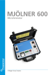
MOM2
MOM2 Win
Microhmmeter
User’s Manual
WWW.MEGGER.COM
ZP-BD03E
MOM2
MOM2 Win
Microhmmeter

User’s Manual
NOTICE OF COPYRIGHT & PROPRIETARY RIGHTS
© 2011, Megger Sweden AB. All rights reserved.
The contents of this manual are the property of Megger Sweden AB. No part of this work may be reproduced or transmitted in any form or
by any means, except as permitted in written license agreement with Megger Sweden AB. Megger Sweden AB has made every reasonable
attempt to ensure the completeness and accuracy of this document. However, the information contained in this manual is subject to change
without notice, and does not represent a commitment on the part of Megger Sweden AB. Any attached hardware schematics and technical
descriptions, or software listings that disclose source code, are for informational purposes only. Reproduction in whole or in part to create
working hardware or software for other than Megger Sweden AB products is strictly prohibited, except as permitted by written license
agreement with Megger Sweden AB.
TRADEMARK NOTICES
Megger® and Programma® are trademarks registered in the U.S. and other countries. All other brand and product names mentioned in this
document are trademarks or registered trademarks of their respective companies.
Megger Sweden AB is certified according to ISO 9001 and 14001.
Megger Sweden AB
Eldarvägen 4
Box 2970
SE-187 29 TÄBY
Sweden
T +46 8 510 195 00
F +46 8 510 195 95
[email protected]
www.megger.com

Contents
1 Safety
.............................................................. 6
Symbols on the instrument................................. 6
Safety instructions.............................................. 6
2 Introduction
.............................................................. 8
To choose measurement time........................... 22
To choose I > I min or I = I max............................. 22
Working at low temperatures........................... 23
Kelvin Clamp/Probe practice............................. 23
Save test results................................................ 23
Hold present test result..................................... 23
Delete present test result.................................. 23
Recalling test results from the log..................... 23
Delete results in the log.................................... 23
Delete all results in the log................................ 23
2.1 Basic technical description.................................... 8
Kelvin test........................................................... 8
5.2 Measurement with max. charge, I=I MAX.......... 24
2.2 DualGround – Both sides grounded..................... 9
5.3 Measurement with minimum current
guarantee, I > I min........................................... 25
3 MOM2 overview
............................................................ 10
3.1 The instrument.................................................. 10
3.2 Accessories........................................................ 12
3.3 Optional accessories........................................... 12
4 Functions and set up
............................................................ 14
4.1 General.............................................................. 14
Internal software version................................... 14
4.2 Test positions..................................................... 14
4.3 Bluetooth – ................................... 15
SET / ............................................................. 15
5.4 Measurement using P/F – pass/fail...................... 26
5.5 Measurement with user defined settings............ 27
5.6 Measurement using the LOG function................ 27
Running numbers mode................................... 27
Circuit breaker testing mode............................. 27
5.7 Measurement using P/F and I min...................... 29
5.8 Trouble shooting................................................ 30
Error messages................................................. 30
6 Application examples
............................................................ 32
6.1 Safety................................................................ 32
Important regarding all testing.......................... 32
4.4 Clock – CLK....................................................... 17
SET / CLK........................................................... 17
6.2 Measurement using Kelvin probes...................... 32
4.5 Minimum current – I min................................... 18
SET / I min......................................................... 18
6.4 Test a CB by injecting through the
ground cables................................................... 33
Disconnection................................................... 33
4.6 Data logger – LOG............................................. 18
SET / LOG.......................................................... 18
4.7 Pass/Fail – P/F..................................................... 19
SET / P/F............................................................. 19
4.8 PC communication – PC COM................................20
PC COM........................................................... 20
4.9 Audio signals..................................................... 20
4.10 Battery power supply....................................... 21
Charging.......................................................... 21
Replacing the batteries..................................... 21
Battery practice................................................. 21
5 Operating instructions
............................................................ 22
5.1 General instructions........................................... 22
Important regarding all testing.......................... 22
Power supply................................................. 22
LCD display....................................................... 22
4
MOM2
6.3 Test a CB using DualGround............................... 33
8 MOM2 Win
............................................................ 34
8.1 Introduction....................................................... 34
8.2 MOM2 installation............................................. 34
Preconditions.................................................... 34
Setup................................................................ 34
Select language................................................ 34
8.3 Start MOM2 Win............................................... 35
Exit MOM2 Win................................................ 35
8.4 Connecting to MOM2........................................ 35
Automatic connecting...................................... 35
Manual connecting........................................... 35
8.5 Read the measurement log................................ 37
Export data to file............................................. 38
Delete all data on the instrument...................... 39
8.6 User settings...................................................... 39
ZP-BD03E

Read existing settings....................................... 39
Program "User" positions................................. 39
8.7 Calibration......................................................... 40
Required equipment......................................... 40
Procedure......................................................... 40
Voltmeter calibration........................................ 40
Ammeter calibration......................................... 40
Calibration report............................................. 41
9 Specifications
............................................................ 42
Specifications MOM2............................................... 42
Index........................................................ 44
ZP-BD03E
MOM2
5
1 Safety
1
Safety
For your own safety and to get the maximum benefit
from your instrument, please ensure that you read
and understand the following safety instructions and
warnings before using the instruments.
Symbols on the instrument
Caution, refer to accompanying documents.
6.
Do not attempt to service the instrument yourself. If you attempt to service the instrument
yourself the warranty is no longer valid.
7.
Do not use any accessories that are not intended for use together with the instrument.
8.
Use a damp cloth for cleaning. Do not use
liquid cleaners or aerosol cleaners.
Important
1.
Protective conductor terminal.
WEEE, Waste Electrical and Electronic
Equipment. Please utilize your local WEEE collection facilities in the
disposal of this product and otherwise
observe all applicable requirements.
Equipment complies with current EU
directives.
▪▪Reorient or relocate the receiving device.
▪▪Increase the separation between the equipments.
Safety instructions
Important
1.
2.
▪▪Connect the equipment into an outlet on a circuit
different from that to which the other device(s) is
connected.
Read and comply with the following
instructions.
Always comply with local safety
regulations.
Warning
Before measuring resistance in circuit breakers
or disconnecting switches (isolators), always
check to see that the object being tested is
closed and grounded at both sides.
If there are current transformers in MOM2's
test circuit, follow the normal procedure to
demagnetize current transformer cores, after
completing your measurements.
3.
Never open a circuit breaker while MOM2 is
connected to it.
4.
Connection points for current cables can become hot during current generation.
5.
High current on output terminals.
6
MOM2
The instrument is intended for use in industrial
environment. It generates, uses and can radiate radio frequency energy and, if not installed
and used in accordance with these instructions
it may cause interference to other devices
in the vicinity. If this equipment does cause
interference with other devices, which can be
determined by turning the equipment off and
on, the user is encouraged to try to correct the
interference by one or more of the following
measures:
▪▪Consult the manufacturer or field service
technician for help.
2.
Never leave the MOM2 unattended while it is
turned on.
3.
It is not possible to use the MOM2 for testing
during battery charging.
4.
Refer all servicing to Megger authorized personnel.
5.
If you need to return the instrument, please
use either the original crate or one of equivalent strength.
ZP-BD03E
1 Safety
ZP-BD03E
MOM2
7
2 Introduction
2
Introduction
The MOM2 is designed to measure the resistance of
circuit breaker contacts, bus-bar joints, contact elements in bus-bars and other high-current links.
When contact resistance rises because of oxidation,
loosened or improperly tightened threaded joints,
temperatures rise abnormally at the points of contact.
This abnormal heating reduces conductivity thereby
accelerating the rise in temperature — and this often
leads to serious trouble.
The MOM2 microhmmeter can be used to detect such
problems early so that they can be remedied long
before trouble starts. Checking contact resistance at
regular intervals provides a clear indication of the state
of your system.
2.1 Basic technical description
The output current is delivered from a supercapacitor
which is charged from the built-in rechargeable batteries.
Kelvin test
The MOM2 uses Kelvin probes or clamps for the
measurement. A Kelvin test uses four wires and measures continuity resistances ensuring all contact and
lead resistances are compensated for, which allows a
much greater accuracy in measurements. Each Kelvin
probe assembly has two probe tips. When contacting
the test object it will be contacted with two plus two
probe tips. One pair is for the current generated. The
other pair will measure the very small voltage present.
Principle for the 4 wire Kelvin test.
8
MOM2
ZP-BD03E
2 Introduction
2.2 DualGround – Both sides
grounded
With MOM2 it is possible to make measurements
according to the DualGround™ method. The most important advantage is improved safety but the method
is also easier and saves time. The number of tasks is
reduced when the ground cable does not need to be
disconnected and reconnected. Permission related
work that may include paper work could many times
be avoided. However, the local safety regulations shall
always be followed.
Using the DualGround method might cause a small
measurement error cause by the current running
through the ground loop. The error value depends on
the relation between the two parallel circuits.
Example: If the test object is 50 µΩ and ground loop
is 10 mΩ the error will be 0.5%
Two 10 m, 95 mm2 grounding cables has a resistance
of around 3.6 mΩ. Transitional resistance in connections and clamps to be added.
With both sides grounded the induced current will not pass
through the test instrument.
ZP-BD03E
MOM2
9
3 MOM2 overview
3
MOM2 overview
3.1 The instrument
1
2
4
3
5
6
7
8
9
Top view
10
MOM2
12
13
10 11
14
Bottom view
ZP-BD03E
3 MOM2 overview
1.
Current output terminal (-)
2.
Current output terminal (+)
3.
Protective conductor terminal
4.
Display
8.
Function selector
OFF
0.1 s
0.6 s
I > I min
3s
▪▪The display offers a combination of analogue arc
and a dual digital readout:
0.1 s
I = I max 0.6 s
3s
▪▪Analogue arc:
Shows the capacitor charge.
▪▪Dual digital display:
Large main digital readout for good visibility of all
main measurement results
Second digital display for additional data.
5.
CLK
OK
6.
TEST button
When the function selector is in any of the positions I > I min , I = I max or USER measurement is performed by pressing the button.
7.
LOG
P/F
PC COM
Press and hold to enable edit of parameters select and confirm parameters. Press shortly to confirm.
Clear / Cancel
Stand-by / Wake up
Press shortly to toggle
internal capacitor
I min
Left, right is used to navigate between
characters/digits.
Up, down is used to change each
character/digit.
Backlight
Automatic switch off after 20 s.
C
Measurement time with
max. charge
Bluetooth “pair units”
▪▪Set date and time
▪▪Set volume for the internal
▪▪Discharge the MOM2
SET
Keys for navigation and to make settings in the
display .
▲▼
Measurement time with
minimum current guarantee
Test positions
buzzer
Keys
◀▶
Test positions
USER
9.
1
2
3
Minimum current guarantee setting
Data log settings
Pass/Fail settings
PC communication (dump
data to PC)
Test positions
Stored settings (Set from
PC SW)
Input for sensing voltage (-)
Connector for the negative test lead.
10.
Input for sensing voltage (+)
11.
Connector for trigger
12.
Battery lid
13.
Connector for the battery charger
14.
Battery charging indicator
Clear log
(Press and hold for 5 s)
ZP-BD03E
MOM2
11
3 MOM2 overview
3.2 Accessories
▪▪Test cables with Kelvin probes (one with trigger)
or
Test cables with Kelvin clamps
▪▪Transport case
▪▪Charger
▪▪Rubber holster
▪▪Carrying strap
▪▪Belt clip
▪▪MOM2 Win
12
MOM2
3.3 Optional accessories
Test cables with Kelvin probes
2 x 1.3 (4 ft) m (one with trigger)
GA-90000
Test cables with Kelvin clamps
1.3 m (4 ft) red, 3 m (10 ft) black
GA-90001
Cable kit 5 m
Current cable 0.5 m (1.6 ft), Connection plate and
sense cables 5 m (16 ft), Ground cable
GA-00380
Cable kit 10 m
Current cable 0.5 m (1.6 ft), Connection plate and
sense cables 10 m (33 ft), Ground cable
GA-00382
Cable kit 15 m
Current cable 0.5 m (1.6 ft), Connection plate and
sense cables 15 m (49 ft), Ground cable
GA-00384
Bluetooth kit
Bluetooth headset and dongle for PC
XC-06000
Calibration kit
BD-90002
ZP-BD03E
3 MOM2 overview
ZP-BD03E
MOM2
13
4 Functions and set up
4
Functions and set up
4.1 General
Internal software version
When turning the function selector from OFF to any
position the display will shortly show a number e.g.
008 and then during five seconds the internal software version e.g. "01C" (revision R01C).
4.2 Test positions
I > I min
Minimum current is set in position SET / I min.
Generation / measurement time: 0.1 s, 0.6 s or 3 s.
I = I max
The current is only limited by the total impedance of
the circuit.
Generation / measurement time: 0.1 s, 0.6 s or 3 s.
USER / 1, 2, 3
User defined settings as generation time, I min, pass/
fail and log.
Note The user defined settings can only be set via
MOM2 Win from a PC
OFF
The instrument should be in the OFF position when
not in use.
Note The MOM2 will go to stand by mode after
about 10 minutes of inactivity. To wake up,
press Stand-by / Wake up (CLR LOG) button.
14
MOM2
ZP-BD03E
4 Functions and set up
4.3 Bluetooth – SET / Display abbreviations
SEt
Set
SPC
Set-up PC
SHS
Set-up headset
Prd
Paired
E-d
Enable / Disable (headset)
EnA
Enabled (headset)
dIS
Disabled (headset)
o
Processing
ErA
Erase all addresses
Enable / Disable Bluetooth
1] Use the ◀ ▶ keys to find "E-d".
2] Press OK to toggle between "EnA" (Enabled
and "diS" (Disabled).
Note Do not use the PC COM mode if there is a
requirement for non-electromagnetic interference in the environment.
The PC COM position is always enabled as it
overrides the disable setting.
6] Check the box and click "Next".
Set up Bluetooth
1] Select SET / on the MOM2.
2] Press ▶, "SPC" will be shown.
3] Press "OK. Display will show "o".
7] The PC should now find the MOM2.
The MOM2 is now visible in the Bluetooth
network and ready to be paired.
4] On the PC, in the "Control Panel" select
"Bluetooth Devices".
5] Click "Add".
ZP-BD03E
MOM2
15
4 Functions and set up
is enabled, "EnA".
3] Press right arrow key twice.
The display shows “SHS”
4] Set the headset in pair mode (See the instructions for the headset.)
5] Press the OK key on the MOM2.
6] When the display shows “Prd” the pairing is
ready.
How to start the headset
1] See the instructions for the headset
8] Check and click Next.
9] Select the second option, see below, enter
"0000" and click Next.
10]Display shows "Prd" and set up is complete.
Note The procedure to pair and assign com port
varies depending on the equipment.
How to pair a headset
1] Select SET / on the MOM2.
2] Use the ◀ ▶ keys to find out that Bluetooth
16
MOM2
ZP-BD03E
4 Functions and set up
4.4 Clock – CLK
blink.
4] Set level (1 to 5) using the ▲ ▼ keys.
SET / CLK
5] Press OK key.
There are three functions in this position:
6] Press ▶ or ◀ to return.
A] Set date and time.
B] Set volume for the internal buzzer.
C] Discharge the MOM2 internal capacitor, (used
for service only).
Display abbreviations
CLC
Clock
UOL
Volume
dIS
Discharge (used for service only)
yy
Year
non
Month
dd
Day
HH
Hour
nIn
Minute
Date and time
1] Select SET / CLC 2] Press and hold OK key until digits start to
blink under the "yy" letters.
3] Set year using the ▲ ▼ keys.
4] Press OK key.
5] Press the ▶ key to go further and set month,
day, hour an minute in the same way as
above.
6] Press C key to return.
Volume for buzzer
1] Select SET / CLC
2] Press ▶ key, "UOL" is shown.
3] Press and hold OK key until digit start to
ZP-BD03E
MOM2
17
4 Functions and set up
4.5 Minimum current – I min
4.6 Data logger – LOG
SET / I min
The data memory can store totally 190 measurements
and this capacity is shared by the two log modes.
Display abbreviations
SEL
Select
Set-up
1] Select SET / I min. Present setting is displayed.
2] Press and hold OK key until digits start to
blink under the "SEL" letters.
3] Select value, 50 or 100, using the ▲ ▼ keys.
SET / LOG
Display abbreviations / description
SEL
Select
oFF
OFF
1A1
Label for Breaker, Phase, Interrupter
1234
Running numbers
LOG modes
OFF
4] Press OK key to confirm.
To cancel press C key or turn the function
selector to another position.
Result after a measurement
If the chosen value is not reached during a measurement it will result in a notification on the display and
by an audio signal.
When the log is OFF only the latest value is stored and only
until the performance of a following measurement, which
overwrites the previous one.
Circuit breaker testing mode,1A1
This mode is primarily designed for measurement on circuit
breakers. The three characters (1A1) are supposed to indicate: Breaker, Phase, Interrupter.
Picture shows an example after a measurement. The I min
limit "50 A" has not been achieved, indicated by the "<"
character to the left.
The current measured during the test is shown in the upper
row. The value shown toggles between the max and min
current during the test. In this case it is the minimum current showing "> 037 A".
Measurement is automatically stored, provided that
there are less than three measurements stored on the
selected object label. Each label can store three measurements. See also section 5.6 Measurement using
the log function.
Running numbers mode, 1234
The measurements are numbered in numerical order (1 to
1999)
18
MOM2
ZP-BD03E
Measurement is automatically stored, provided that
the memory is not full.
Set-up
1] Select SET / LOG. Present setting is displayed.
2] Press and hold OK key until characters start
to blink under the "SEL" letters.
3] Use the ▲ ▼ keys to select mode.
4] Press OK key.
4.7 Pass/Fail – P/F
In the P/F position you can enable and set the limit for
the Pass/Fail function. If the measured value exceeds
the set limit it will result in a notification on the display and by an audio signal
SET / P/F
Display abbreviations
SEL
Select
oFF
OFF
Set-up
1] Select SET / P/F. Present setting is displayed.
2] Press and hold OK key until character, "<" or
"oFF" start to blink.
3] Select "oFF" or a value using the ▲ ▼ keys.
4] Use the keys ▶ ◀ to select the digit to
change, it will blink.
5] Use the keys ▲ ▼ keys to set the desired
value.
6] Press OK key.
To cancel press C key or turn the function
selector to another position.
4 Functions and set up
4.8 PC communication – PC COM
4.9 Audio signals
The PC COM position is used for all operations performed from a PC using MOM2 Win. You can:
The MOM2 emits different sounds to give an audible
information / confirmation of an event / action. The
sound is emitted from a built-in buzzer and from the
Bluetooth headset (optional). The audio signals vary in
frequency, Low / High, and composition.
▪▪Dump measurement data from the MOM2
▪▪Delete all measurements in the data log
▪▪Program "User" positions
Audio signals
Description
◼◼◼...
The MOM2 is charging the
capacitor and is not ready for
measurement.
▪▪Set MOM2 clock
▪▪Calibrate
PC COM
Display abbreviations
rEn
◼◼◼◼...
Remote
Set-up
Battery low
During capacitor charge
Measurement in progress
◼◼
The following is needed:
▪▪A PC with MOM2 Win installed
See chapter 8 MOM2 Win
◼◼
Pass signal
Measurement complete / Pass
Wake up
◼◼ ◼
Fail signal
Measurement complete / Fail
Label full
Stand-by
▪▪A PC connected via Bluetooth
See section "Bluetooth set up"
When pressing Test / Trigger
while lock symbol is shown
◼
◼ ◼◼
Delete confirmed
When press and hold the
Test / Trigger
Note: Only in LOG mode
◼◼
Hold
When pressing Test / Trigger
Note: Only in LOG mode
◼◼
Release
When pressing Test / Trigger
Note: Only in LOG mode
Legend
20
MOM2
◼
◼◼
◼
◼◼
...
Short - High tone
Long - High tone
Short - Low tone
Long - Low tone
Continuous
ZP-BD03E
4 Functions and set up
4.10 Battery power supply
It is recommended to use the same type of batteries
(AA (HR6) 2700 mAh NiMH) as the original ones.
Charging
Note It is possible to use standard (non-rechargeable)
Before using the MOM2 the batteries should be
charged. Use the supplied charger and connect it
to the socket at the bottom of the MOM2. Typical
recharge time for fully discharged batteries is 3 hours,
at 25°C (77°F).
Tip
alkaline cells but then only for test using the 0.1 s
measurement position and I > I min.
Place the MOM2 upside down to get better the cooling of the batteries.
Important
MOM2 cannot be used for testing during
charging.
LED
Description
indicator
Clarification /
Remedy
Green
Fully charged
Yellow
Green
Charging
Red
Yellow
Green
Temperature limits Charging will restart
exceeded during
when temperature
the charging.
has decreased.
Red
Green
Temperature limits Charging will start
exceeded, too
when temperature is
high or too low,
within the limits.
before charging.
Red
Fault state. Wrong Disconnect the
battery type,
charger and check
faulty battery.
the batteries.
None
Battery fault /
missing or other
fault
Loosen the two screws that holds the battery lid at the back
of MOM2.
Important
Always replace all batteries at the same
time.
Do not mix old and new batteries.
Do not mix types or brands.
Battery practice
To extend the battery life cycle time it is a god practice
to recondition the batteries in a separate charger that
has recondition options like refresh / discharge. It is
a good idea to condition the batteries once in about
6 months or after around 12 regular charge cycles to
get the most out of them.
Check batteries and
charger / cables
Replacing the batteries
1] Loosen the two screws that holds the battery
plate at the back of MOM2, see figure below.
ZP-BD03E
MOM2
21
5 Operating instructions
5
Operating instructions
5.1 General instructions
5
6
7
Important regarding all testing
Read and comply with the
safety instructions.
Important Always comply with local
safety regulations.
Power supply
Prepare testing by charging the batteries se section
4.10 Battery power supply.
5.
Note The MOM2 cannot be used for testing during
battery charging.
See section 5.8 Troubleshooting
6.
LCD display
Pass/Fail indicator
In this case the Pass/Fail is set to 100 μΩ
The display can be backlighted by pressing the key
It is switched off automatically after 20 seconds.
1
Warning
2
3
4
.
7.
Padlock symbol
The lock symbol is shown when the capacitor
is charged prior to a test and when you lock a
test result.
To choose measurement time
In an environment without electrical interference it is
wise to choose the shortest measurement time, which
means that you can get the largest number of measurements on a single battery charge.
Note The shortest measurement time (0.1 s) is not
suitable in environments with a frequency of
16 2 / 3 Hz.
1.
Analogue arc
Indicates level of the capacitor charge
2.
Measurement label
In this case the instrument is set in Running
numbers mode (SET / LOG)
3.
Measurement result
4.
Battery charge indicator
Tip: Start making three tests with the
shortest measurement time to figure out
if the results vary. If they do not differ
significantly - use 0.1 s for the tests.
To choose I > I min or I = I max
If you want maximum current for your test choose
I = I max. In this position the capacitor will be charged
to its maximum and therefore requires much energy
from the batteries.
If lower current is sufficient for the measurement,
it is advisable to use the I > I min position. In the
22
MOM2
ZP-BD03E
5 Operating instructions
SET / I min position you select the minimum current to
be 50 A or 100 A.
Min current guarantee Max current
(I > I min)
(I = I max)
Valid for test objects ≤ 2 mΩ
For all test objects, 0 – 1 Ω
Capacitor only charged to
sufficient level to generate
selected minimum current for
set time
Saves instrument battery
Capacitor is fully charged
Will push as much current as
possible through the test object
for set time. Current is determined as: I ≈ 2.5 V / [test object
R + 0.01 Ω] A
Allows for shorter time between tests
Requires longer capacitor
recharge times
Kelvin probe or the TEST button.
Delete present test result
1] Press and hold, about 1 s, the trigger on the
Kelvin probe or the TEST button just after a
measurement.
The latest test result is deleted from screen
and log. This is also confirmed by an audio
signal.
Note This is also possible to carry out when the
result is locked on display.
Working at low temperatures
Recalling test results from the log
MOM2 can be operated down to -20°C provided that
the batteries keep a temperature over 0°C. When the
instrument is in use the batteries will generate heat
enough to keep themselves warm.
1] Saved results can be recalled by scrolling to
Kelvin Clamp/Probe practice
Important
To avoid adding unwanted transition
resistances to the measurement result the
Kelvin clamps or Kelvin probes shall be
connected directly to the test object and
not to e.g. a bolt head.
In some cases it might be advisable to use
separate sense cables, forming a conventional four point measurement, in order
to get a more accurate voltage sense.
Save test results
A] When LOG is activated measurement results
desired label using the ▲ ▼ keys.
Delete results in the log
1] Select label using the ▲ ▼ ◀ ▶ keys.
2] By pressing the C key the display will prompt
"CLR" in big characters.
3] Delete by pressing the OK key. Cancel can be
done by pressing the C key.
Note In Circuit breaker testing mode the measurement results will be deleted one at a time.
Delete all results in the log
1] Press and hold, for 5 s, the red button below
the TEST button.
Note This will delete the log memory for both log
modes, Circuit breaker testing and Running
numbers.
are automatically saved in the memory.
B] When the log is OFF only the latest value is
stored and only until the performance of a
following measurement, which overwrites
the previous one.
Hold present test result
When the LOG function is activated the measurement
result is shown on the display for about 3 seconds.
After that it is stored in the memory. If you want to
study the result longer you can lock the display view
by doing as follows.
1] Press shortly the trigger on the Kelvin probe
or the TEST button just after a measurement.
The latest test result is locked and shown on
the display. This is confirmed by a padlock
symbol on the display and an audio signal.
2] To unlock, press shortly the trigger on the
ZP-BD03E
MOM2
23
5 Operating instructions
5.2 Measurement with max.
charge, I=I MAX
the maximal and minimal current values during the test. "268 A" and "250 A"
1] Read the section 5.1 General instructions.
2] If applicable, connect the ground cable (protective earth).
3] Make the desired settings in the SET options.
In this example LOG and P / F are disabled (set
to OFF).
4] Attach the test cables.
5] Turn the function selector to desired I = I max
position.
The instrument indicates that it is charging
the capacitor by a repeated sound and on
the display shows alternating "CAP" and
"CHG" and the lock symbol.
Pictures shows the two display views..
Charging
6] The MOM2 is ready for a measurement when
the lock symbol disappears.
Ready for test
7] Press the TEST button on MOM2 or the pull
the trigger on the probe.
A continuous audio signal tells that the
measurement is in progress.
Two short signals tells that the measurement
is complete.
8] The result is shown on the display, see figures
below.
Over the resistance value "100 μΩ" toggles
24
MOM2
ZP-BD03E
5 Operating instructions
5.3 Measurement with
minimum current guarantee,
I > I min
1] Read the section 5.1 General instructions.
A] If the current value is over the set min current
limit the result will be shown on the display
with big digits.
The small digits toggle between max and min
current value.
2] If applicable, connect the ground cable (protective earth).
3] Make the desired settings in the SET options.
Select I min to 50 or 100 A (in this example
set to 100 A).
In this example LOG and P / F are disabled (set
to OFF).
4] Attach the test cables.
5] Turn the function selector to desired I > I min
position.
The instrument indicates that it is charging
the capacitor by a repeated sound and on
the display shows alternating "CAP" and
"CHG" as well as the padlock symbol.
Pictures shows that the test current was below 219 A and
over 205 A.
B] If the current value is below the set min current limit there is the fail signal and the <
character is displayed to the left of the set
min current value.
Picture shows that the test current was below 100 A.
Charging
6] When the lock symbol disappears the MOM2
is ready for a measurement.
Ready for test
7] Press the TEST button on MOM2 or Trigger
on the probe.
A continuous audio signal tells that the
measurement is in progress.
Two short signals tells that the measurement
is complete.
ZP-BD03E
MOM2
25
5 Operating instructions
5.4 Measurement using P/F –
pass/fail
1] Make the desired settings in the SET options
Select P/F and enter desired limit value.
In this example LOG is set to OFF
2] Turn the function selector to one of the test
positions.
3] Press the TEST button on MOM2 or the pull
The small digits show the set P/F value (< 90 μΩ).
The character ">" to the left of the big digits indicates that
the P/F value was exceeded.
the trigger on the probe.
A continuous audio signal tells that the
measurement is in progress.
Another signal tells that the measurement is
complete, pass or fail.
A] If the resistance value is below the P/F limit.
The result will be shown on the display with
big digits.
The small digits toggle between the P/F limit
and the max, min current values.
The minimum current was 80 A and the resistance value is
102 μΩ.
Here P/F limit was set to 150 µΩ and the measured resistance value is 100 μΩ.
Max current during test was 219 A.
Min current during test was 205 A
B] If the resistance value is over the P/F limit
there is the fail signal and the > character is
displayed to the left of the set P/F value.
26
MOM2
ZP-BD03E
5 Operating instructions
5.5 Measurement with user
defined settings
5.6 Measurement using the
LOG function
There are three positions for storing user defined
settings. These can only be set via a PC with the
MOM2 Win Software, see chapter MOM2 Win.
See section 4.6 Data logger – LOG for how to set up.
Running numbers mode
The measurements are numbered in numerical order
1 to 1999
Measurement is automatically stored, provided that
the memory is not full (Running numbers =1999).
The display before first measurement.
The display after measurements
By using the ◀ ▶ and ▲ ▼ keys you can scroll between the saved test results.
Note You can only scroll through the measurements
in the selected LOG mode
Circuit breaker testing mode
Each label e.g. 1A1 in the memory for the circuit
breaker measurement can contain three measurements. These are indicated by commas, see picture
below.
The label is built of three elements
▪▪Two-digit indication of circuit breaker (1 to 19)
▪▪A letter for phase (A,B,C)
▪▪Digit for interrupter (1 to 9)
ZP-BD03E
MOM2
27
5 Operating instructions
1
2
The display after measurements
3
When three measurements have been done and saved
to a label e.g. 1A1 the lock sign is shown.
Note To continue to measure you need to either
delete the latest measurement or scroll to a
blank label.
By using the ◀ ▶ and ▲ ▼ keys you can toggle between the saved test results
4
5
6
1.
The first measurement on the present label
shown by a comma.
2.
The second measurement in the present
memory cell shown by a comma.
3.
The third measurement in the present memory
cell shown by a comma.
To view all measurements stored on the
same label
4.
Digit for the circuit breaker
1] Press the ▲ ▼ keys until an arrow sign is
5.
Letter for the phase
6.
Digit for the interrupter
The display before measurement
The display shows "3" for the third measurement for the
specific label. The arrow sign to the left only represents the
omitted characters to the left of the digit "3".
shown to the left.
2] Scroll between measurements 1, 2 and 3 by
using the ◀ ▶ keys.
Example: Three measurements on one label
are shown as e.g. "1A1-1", "1A1-2", "1A1-3".
Note You can only scroll through the measurements
in the selected LOG mode
The display before first measurement, one comma:
The display before second measurement, two commas:
The display before third measurement; three commas.
28
MOM2
ZP-BD03E
5 Operating instructions
5.7 Measurement using P/F
and I min
In this example LOG is set to OFF.
current limit the result will be shown on the
display with big digits e.g. as below.
The small digits toggle between max and min
current value and the P/F limit.
1] Read the section 5.1 General instructions.
2] If applicable, connect the ground cable (protective earth).
3] Make the desired settings in the SET options.
Select P/F and enter desired limit value.
Select I min (50 or 100 A).
4] Attach the test cables.
5] Turn the function selector to desired I > I min
position.
The instrument indicates that it is charging
the capacitor by a repeated sound and on
the display shows alternating "CAP" and
"CHG" as well as the padlock symbol.
The minimum test current was 80 A and resistance is
102 µΩ.
B] If the resistance value is over the P/F limit
there is the fail signal and the > character is
displayed to the left of the set P/F value.
The small digits show the set P/F value (< 90 μΩ).
The character ">" to the left of the big digits indicates that
the P/F value was exceeded.
C] If the current value is below the set min current limit there is the fail signal and the <
character is displayed to the left of the set
min current value.
Charging
6] When the lock symbol disappears the MOM2
is ready for a measurement.
The maximum test current was 82 A and the test current
was below 100 A.
D] If both the P/F limit and the current limit are
Ready for test
contravened, the big digits will toggle between resistance value, < current limit and >
P/F limit.
Press the TEST button on MOM2 or pull the
trigger on the probe.
A continuous audio signal tells that the
measurement is in progress.
When the measurement is complete there
will be a pass or a fail signal.
A] If the resistance value is below the P/F limit
and the current value is over the set min
ZP-BD03E
MOM2
29
5 Operating instructions
5.8 Trouble shooting
Problem
Solution
Headset does
not work
Check that it is paired to MOM2
Check on MOM2 that Bluetooth
is enabled
Error messages
Message
Cause
Remedy
"OL"
Bad connection
/ resistance out
of measurement
range
Check cables and connections
Warning sign
on display and
the battery
charge indicator blinks
The batteries
cannot charge
the capacitor
Charge the batteries
Note: It might be possible
to proceed and make some
tests if it is realistic to select
a test position that requires
less power (shorter measuring time).
Warning sign
on display
A thermal
protection has
tripped.
Turn off the MOM2 and let it
cool down.
30
MOM2
ZP-BD03E
5 Operating instructions
ZP-BD03E
MOM2
31
6 Application examples
6
Application examples
6.1 Safety
Important regarding all testing
Read and comply with the
safety instructions.
Important Always comply with local
safety regulations.
Note If you are measuring resistance in a circuit
breaker or disconnecting switch (isolator),
make sure that it is closed and grounded at
both sides before testing.
6.2 Measurement using Kelvin
probes
An example how to perform testing using the two
Kelvin probes. This example describes the performance if you only want to know if the test object pass
a preset value and you do not need to store the test
results.
1] Select LOG function "OFF", and set P/F value
(see section 4.6 and 4.7).
2] Attach the test cables with Kelvin probes (2 x
1.3 m) one with a trigger, to MOM2.
3] Turn the function selector to desired position.
4] Hook the instrument to your belt or use the
strap.
5] Press and hold the two Kelvin probes to the
test object and pull the trigger.
If the value is outside the limits there is a
sound telling the result was fail.
The measurement value remains until another measurement is performed or until the
instrument is switched off.
Measurement on a test object
32
MOM2
ZP-BD03E
6 Application examples
6.3 Test a CB using
DualGround
6.4 Test a CB by injecting
through the ground cables
You can perform testing with both sides grounded.
However the measurement accuracy will be somewhat lower with both sides grounded depending on
the ratio of the currents – circuit breaker / grounding
cables (see section 2.2). This example shows a test on
a HV CB using a man lift.
1] The circuit breaker (CB) shall be disconnect-
1] The circuit breaker shall be disconnected,
closed and grounded on both sides.
2] Attach the black (3 m) test cable with Kelvin
clamp and the Kelvin probe with trigger to
the instrument.
3] Hook the MOM2 to your belt or use the strap
to hang it around your neck.
4] Attach the black test cable with Kelvin clamp
to one side of the CB using the man lift.
5] Move yourself to the other side of the CB using the manlift.
6] Press and hold the Kelvin probe to the test
object and pull the trigger.
ed, closed and grounded on both sides.
2] Connect the MOM2 to ground.
3] Attach an extra ground cable (not included)
with at least 95 mm2 cross section area to one
side of the CB.
4] Connect the 0.5 m current cable to the current out minus terminal on the MOM2 and
attach the other end to ground close to
where the CB's grounding cable is attached.
(the opposite side of CB from where the extra ground cable is attached).
5] Mount the 0.1 m plate to the current out
plus terminal on the MOM2 and attach the
extra ground cable to the plate.
6] Connect the sensing cables (red and black) to
the CB.
7] Remove the original CB grounding cable on
the side where the extra grounding cable is
attached.
8] Press the TEST button.
Measurement on CB with both sides grounded.
Note The test can also be done by using two Kelvin
clamps.
Traditional measurement from ground. Injection is done
through existing grounding cable (earthing). Optional cable
kit is needed. Available kits have 5, 10 or 15 m cables.
Disconnection
1] Re-attach the original CB grounding on the
side where the extra grounding is attached.
2] Disconnect the sensing cables from the CB.
3] Disconnect the extra ground cable from the
0.1 m plate on plus terminal.
4] Disconnect the 0.5 m current cable from
ground.
5] Disconnect the ground cable from MOM2.
ZP-BD03E
MOM2
33
8 MOM2 Win
8
MOM2 Win
8.1 Introduction
8.2 MOM2 installation
MOM2 Win is a Windows® program that communicates with the MOM2 microhmmeter instrument.
Preconditions
It is used for:
▪▪Windows XP / 7
▪▪Reading measurement data from the instrument and save
▪▪.net Framework 4.0
it to file
▪▪Configuring the instrument
▪▪Calibrating the instrument
If the PC has not the .net Framework 4.0 installed it
will automatically be installed provided that the PC is
connected to internet.
▪▪USB Bluetooth dongle
The USB Bluetooth dongle must be installed, see the
installation instructions supplied with the dongle.
Setup
1] Insert the MOM2 Win CD into the CD-drive.
The installation will start automatically. If not
select and run the file "Setup.exe" to install
the program.
The program will be installed in the folder C:\Program
Files\Programma\Mom2 Win with program shortcuts on the desktop and in the Start->All programs>Programma folder.
Select language
1] Under "Settings" menu, select "Language".
All texts in all open windows will be updated
with the selected language.
Note If the translation is missing for some texts the
default language (English) will be used.
The language selection does not change the
time format or decimal separator which instead follows the Windows regional settings.
34
MOM2
ZP-BD03E
8 MOM2 Win
8.3 Start MOM2 Win
8.4 Connecting to MOM2
1] Click the MOM2 icon on the desktop or
To establish the Bluetooth connection the MOM2
must be paired to the PC, see section 4.3.
run the file Mom2Win.exe
(Start->All programs->Programma)
The program will startup showing the start
page.
Automatic connecting
1] Turn the function selector to the PC COM
position on the MOM2 instrument.
At program startup the SW will try to connect to
MOM2 using the same COM port that the last successful connection used. If there have been no previous MOM2 connections from this computer the SW
will scan all available COM ports. If there are several
paired MOM2 instruments nearby the SW will connect to the first one detected. The connection status is
shown on the start page, see Figure 8.3.1.
Manual connecting
1] Open the "Connection settings" window
from the "Settings" menu or double-click on
the connection status text field on the start
page.
The "Connection settings" window will then
pop up, see figure below
Figure 8.3.1 Start page
Exit MOM2 Win
1] Exit the program by selecting "Exit" from the
"File" menu or by clicking on the "X" button
in the upper right corner of the window.
The program will ask for a confirmation before it closes.
Figure 8.4.1 The Connection settings window, no connection established.
ZP-BD03E
MOM2
35
8 MOM2 Win
2] Choose a COM port in the drop down list and
click the "Connect" button.
The program will try to connect to a MOM2
instrument over the specified COM port.
If it is unknown which COM port to use the program
can scan all available ports until it finds a MOM2
instrument.
3] Click the button “Scan for MOM2”.
The operation can be interrupted with the
“Cancel scan” button.
Figure 8.4.3 The Connection settings window, connection
established.
Refresh button
Provided that the MOM2 and the PC are connected
to each other the "MOM2 date and time" and the
"PC date and time" fields are updated every time you
open the "Connection settings" window or when you
click the "Refresh" button, see Figure 8.4.3
Synchronize clock PC -> MOM2
Figure 8.4.2 The Connection settings window, searching.
36
MOM2
When you click the “Synchronize clock PC -> MOM2”
button the PC system time is written to the MOM2.
This is the easiest way to set the clock in MOM2, see
Figure 8.4.3
ZP-BD03E
8 MOM2 Win
8.5 Read the measurement log
1] Click the "Measurements" button on the
Start page or select "Measurements" from
the "Tools" menu.
Figure 8.5.1 Data dumping dialog.
2] Click on the "Retrieve all data" button to
download all measurements stored in the
instrument.
A window will pop up showing the progress
of the download.
At any time the data dump can be stopped
by clicking the "Cancel" button. In that case
the data window will be closed.
Figure 8.5.2 Data dumping progress.
ZP-BD03E
MOM2
37
8 MOM2 Win
Figure 8.5.3 Data dumping finished. The columns can be
sorted by clicking the headers and arranged by click-hold
and drag.
Export data to file
1] Click the "Save to file" button (this button is
not enabled if the list is empty).
A "Save as" window will be opened.
2] Type a file name and click the "Save" button
to export the data to file.
A] The default file type is (*.csv) which will save
the data as an ASCII file with comma separated values, suited for import to e.g. Microsoft
Excel.
Note The value separator is dependent of the regional setting in Windows, a semicolon when
comma is used for decimal separator and
comma otherwise.
The format of the exported data is not the same as
what is seen in the measurements table. There is no
mixing of values and units, the units are placed in the
column headers.
B] If file type (*.txt) is selected the data will be
saved with the values separated by tabs.
38
MOM2
ZP-BD03E
8 MOM2 Win
Delete all data on the instrument
1] In the "Measurements" window, click the
"Delete all data" button to erase all the
measurements in the instrument log.
8.6 User settings
1] Click the Program "User" positions" button
on the start page or choose Program "User"
positions from the "Tools" menu .
Figure 8.6.1 Program "User" positions
Read existing settings
Figure 8.5.4 Delete all measurements progress.
1] Select "User" position No." (1 – 3).
2] Click the "Read from instrument" button to
see the current settings on the instrument.
All three user settings will be read, not only
the one selected in the combo box. The values for minimum current, pass/fail limit and
type of logging will be updated.
Program "User" positions
1] Make the desired settings and click the "Save
to instrument" button.
Note All three User positions will be updated on
the instrument, not just the currently selected
one.
ZP-BD03E
MOM2
39
8 MOM2 Win
8.7 Calibration
6] Repeat from step 1 for the next two ranges.
Required equipment
▪▪Stable DC voltage source
▪▪Calibrated reference voltmeter
▪▪Reference shunts 1 mΩ and 10 mΩ
Procedure
1] Click the "Calibration" button on the Start
page or select "Calibration" from the "Tools"
menu to switch to the calibration page.
The existing calibration factors will be read
from the instrument and the calibration page
will be disabled until it is finished.
Figure 8.7.2 Voltmeter calibration
Ammeter calibration
Note The voltmeter in the instrument must be
calibrated before it is possible to calibrate the
Ammeter.
The ammeter is calibrated in an indirectly manner by
measuring the resistance over two predefined shunts
and compare with the reference values. The resistance
is measured with a capacitor voltage suitable for the
voltage and current ranges.
1] Connect the current cables from the MOM2
to the reference shunt
2] Connect separate sense leads from the
Figure 8.7.1 Calibration page. Loading calibration factors
during startup.
Voltmeter calibration
The voltmeter should be tested in three ranges.
1] Connect the voltage source to the MOM2
sense input, correctly polarized
2] Adjust voltage so that it falls within ±10%
of the stated reference voltage, using the
calibrated voltmeter.
MOM2 sense input to the sense outputs of
the reference shunt
3] Enter the value of the shunt in the "R reference" input field.
The "Measure" button will be enabled if the
resistance is within the limits.
4] Click the "Measure" button next to the field.
When the measurement is started a progress
window is shown, see fig. below. The two
uppermost fields show the measured capacitor voltage and the target voltage.
3] Type the value in the U reference column in
MOM2 Win
4] Click the "Measure" button next to the field.
The value measured by the MOM2 will then be
propagated to the "U measured" text field.
New calibration factors will automatically be
calculated.
5] Click the "Verify" button.
The voltage measured with the new calibration
factor will be shown in the "U Verified" field. The
deviation (in percent) from the reference value
will be shown to the right.
40
MOM2
Figure 8.7.3 Resistance measurement progress window
ZP-BD03E
8 MOM2 Win
5] The measurement goes on and when it is finished
the "R Measured" field is filled with the measured resistance value and a new calibration factor
for this measurement range is calculated, see fig.
below.
Figure 8.7.4 Ammeter calibration.
6] Click the "Verify" button.
A measurement is started and the "Resistance measurement in progress" window will
be shown.
7] Repeat from step 1 for the next reference
Figure 8.7.5 Calibration report.
shunt.
When the resistances over both the shunts
have been measured and the result is satisfactory you can save it to the MOM2.
8] Click the"Save to instrument" button.
9] If the result of the tests is not satisfying or
you want to start over, click the "Cancel"
button.
This will empty the calibration dialog and the
calibration factors are read from the instrument again.
Calibration report
1] Click the "Calibration Report" button to
show a preview of a calibration report.
It can be opened at any time during the
calibration. However, a complete report with
a calibration time can only be made when
the calibration is completed and saved to the
MOM2.
2] The calibration report can be printed, either
by pressing ctrl-P or clicking on the "Print
report"button.
ZP-BD03E
MOM2
41
9 Specifications
9
Specifications
Specifications MOM2
Specifications are valid at fully charged batteries and an ambient temperature of +25°C, (77°F). Specifications are subject to
change without notice.
Environment
Application field
Temperature
Operation
Storage
Relative humidity %RH
Pollution degree
Shock
Vibration
Transport
Flammability class
For use in high-voltage substations
and industrial environments.
-20ºC to +50°C (-4°F to +122°F) *)
-40ºC to +70ºC (-40°F to +158°F)
5%-95%, non condensing
2
IEC 60068-2-27
IEC 60068-2-6
ISTA 2A
V0
*) Battery operation temperature 0ºC to +50° (32°F to +122°F)
Battery charging temperature +10ºC to +40° (50°F to +104°F)
CE-marking
EMC
LVD
2004/108/EC
2006/95/EC
Measurement section
Minimum current guarantee
Pass / Fail
Number of measurements
on fully charged batteries
Interference suppression
Range
Range selection
Resolution
0 – 999 µΩ
Selectable 50 A / 100 A
Valid at resistance ≤2mΩ
Settable from 1 µΩ to 1999 mΩ
typ. 2200 at I min = 50 A and 0.1 s
typ. 800 at I min = 100 A and 0.1 s
Yes
0 - 1000 mΩ
Auto
1.0 – 9.99 mΩ
10.0 – 99.9 mΩ
100 – 1000 mΩ
Inaccuracy
0 – 1999 µΩ
2 – 1000 mΩ
0.01 mΩ
0.1 mΩ
1 mΩ
Mains voltage
Power consumption
Protection
Five AA (HR6) 2700 mAh NiMH cells
< 12 h
3h
100 - 250 V AC, 50 / 60 Hz
60 W
Against wrong battery type, low/high
temperature.
Real time clock battery life ≥10 years
Audible feedback
Different buzzer sounds
User presets
3
Field calibration
Yes
Encapsulation
IP54
Dimensions (excl. binding 217 H x 92 B x 72 D mm
posts)
8.5 H x 3.6 B x 2.8 D in.
Weight
1.0 kg (2.2 lbs) instrument only
5.0 kg (11 lbs) with accessories and
carrying case
42
MOM2
±1 % of reading ±1 digit
±2 % of reading ±1 digit
Outputs + / –
Range
> 100 A DC (R < 2 mΩ)
Output voltage (max)
Generation duration
2.5 V DC
Selectable: 0.1 s, 0.6 s, 3 s
Recovery time at I min set to 100 A
and load 100 μΩ
Max
Typ
10 s
8s
20 s
16 s
130 s
100 s
General
Battery power
Recharge time
Typical recharge time at
25°C
Battery charger
1 µΩ
Generation time
0.1 s
0.6 s
3s
Inputs
SENSE + / –
Connector
4 mm banana jack
Voltage
Trigger input
±3 V DC
Threshold 8 V DC
DC IN
12 – 24 V DC, 2 A max
Logger
Logger, Data
Labeling schemes
Capacity
Label. Timestamp, I max, I min, I Limit, Resistance, Meas.time, P/F limit
Circuit breaker oriented or running
numbers
190 measurements
Wireless communication
Headset
Bluetooth
PC communication
PC communication
Bluetooth
Bluetooth
ZP-BD03E

ZP-BD03E
MOM2
43
Index
Index
Input for sensing voltage (-).....................................11
Input for sensing voltage (+)....................................11
A
J
Accessories..............................................................12
Application examples...............................................32
Audio signals...........................................................20
B
Basic technical description..........................................8
Battery charging......................................................21
Battery charging indicator........................................11
Battery charging LED
indicator..................................................................21
Battery lid................................................................11
Battery power supply...............................................21
Bluetooth.................................................................15
Both sides grounded..................................................9
C
Calibration...............................................................40
Clear log..................................................................11
CLK.........................................................................17
Clock.......................................................................17
Connector for the battery charger............................11
Connectors for trigger.............................................11
Current output terminal (-).......................................11
Current output terminal (+)......................................11
D
Delete all reults........................................................23
Delete present test result.........................................23
Delete results...........................................................23
display.....................................................................22
Display.....................................................................11
DualGround...............................................................9
E
F
Functions.................................................................14
Functions and set up................................................14
Function selector......................................................11
G
K
Kelvin Clamp/Probe practice.....................................23
Kelvin test..................................................................8
Keys.........................................................................11
L
LCD display..............................................................22
LOG.........................................................................18
low temperatures.....................................................23
M
Measurement on using Kelvin probes.......................32
measurement time...................................................22
Measurement using P/F............................................26
Measurement using P/F and I min............................29
Measurement using the LOG function......................27
Measurement with max. charge, I=I MAX................24
Measurement with minimum current guarantee,
I>I MIN....................................................................25
Measurement with user defined settings..................27
MOM2 installation...................................................34
MOM2 Win.............................................................34
N
O
OFF..........................................................................14
Operating instructions..............................................22
Optional accessories.................................................12
overview..................................................................10
P
Pass/Fail...................................................................19
PC COM..................................................................20
PC communication...................................................20
P/F...........................................................................19
Protective conductor terminal..................................11
Q
R
H
Hold present test result............................................23
Recalling test results.................................................23
Replacing batteries...................................................21
S
I
I min........................................................................18
44
MOM2
Safety........................................................................6
Safety instructions......................................................6
ZP-BD03E
Index
Save test results.......................................................23
set up......................................................................14
Specifications...........................................................42
Stand-by / Wake up.................................................11
Symbols on the instrument........................................6
T
Test a CB by injecting through the ground cables.....33
Test a CB using DualGround.....................................33
TEST button.............................................................11
Test positions...........................................................14
To choose I > I min or I = I max....................................22
To choose measurement time...................................22
Trouble shooting......................................................30
U
USER – 1/2/3.............................................................14
V
W
Wake up..................................................................11
X
Y
Z
ZP-BD03E
MOM2
45
Index
46
MOM2
ZP-BD03E
Index
ZP-BD03E
MOM2
47
Your “One Stop” Source for all your electrical test equipment needs
▪▪Battery Test Equipment
▪▪Cable Fault Locating Equipment
▪▪Circuit Breaker Test Equipment
▪▪Data Communications Test Equipment
▪▪Fiber Optic Test Equipment
▪▪Ground Resistance Test Equipment
▪▪Insulation Power Factor (C&DF) Test Equipment
▪▪Insulation Resistance Test Equipment
▪▪Line Testing Equipment
▪▪Low Resistance Ohmmeters
▪▪Motor & Phase Rotation Test Equipment
▪▪Multimeters
▪▪Oil Test Equipment
Megger is a world leading manufacturer and
supplier of test and measurement instruments
used within the electric power, building wiring and
telecommunication industries.
▪▪Portable Appliance & Tool Testers
▪▪Power Quality Instruments
▪▪Recloser Test Equipment
▪▪Relay Test Equipment
With research, engineering and manufacturing
facilities in the USA, UK and Sweden, combined
with sales and technical support in most countries,
Megger is uniquely placed to meet the needs of its
customers worldwide.
▪▪T1 Network Test Equipment
▪▪Tachometers & Speed Measuring Instruments
▪▪TDR Test Equipment
For more information about Megger and
its diversified line of test and measurement
instruments:
www.megger.com
▪▪Transformer Test Equipment
▪▪Transmission Impairment Test Equipment
▪▪Watthour Meter Test Equipment
▪▪STATES® Terminal Blocks & Test Switches
Megger is certified according to ISO 9001 and
14001.
▪▪Professional Hands-On Technical and
▪▪Safety Training Programs
UK
Archcliffe Road, Dover
CT17 9EN England
T +44 (0) 1304 502101
F +44 (0) 1304 207342
[email protected]
Other Technical Sales Offices
Dallas USA
Norristown USA
Toronto CANADA
Trappes FRANCE
Oberursel GERMANY
Johannesburg SOUTH AFRICA
Kingdom of BAHRAIN
Mumbai INDIA
Chonburi THAILAND
Sydney AUSTRALIA
WWW.MEGGER.COM
SWEDEN
Megger Sweden AB
Eldarvägen 4
Box 2970
SE-187 29 TÄBY
T +46 8 510 195 00
F +46 8 510 195 95
[email protected]
Megger is a registered trademark
Subject to change without notice. Printed matter No. ZP-BD03E Doc. BD0333AE V01 2011