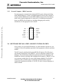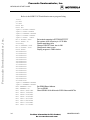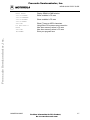
1
Freescale Semiconductor, Inc.
M68MPB333UM/D
REV 1
Freescale Semiconductor, Inc...
March 1998
M68MPBF333
MCU PERSONALITY BOARD
USER’S MANUAL
© MOTOROLA, INC., 1994, 1998; All Rights Reserved
For More Information On This Product,
Go to: www.freescale.com
Freescale Semiconductor, Inc...
Freescale Semiconductor, Inc.
Motorola reserves the right to make changes without further notice to any products herein to
improve reliability, function or design. Motorola does not assume any liability arising out of the
application or use of any product or circuit described herein; neither does it convey any license
under its patent rights nor the rights of others. Motorola products are not designed, intended, or
authorized for use as components in systems intended for surgical implant into the body, or other
applications intended to support or sustain life, or for any other application in which the failure of
the Motorola product could create a situation where personal injury or death may occur. Should
Buyer purchase or use Motorola products for any such unintended or unauthorized application,
Buyer shall indemnify and hold Motorola and its officers, employees, subsidiaries, affiliates, and
distributors harmless against all claims, costs, damages, and expenses, and reasonable attorney
fees arising out of, directly or indirectly, any claim of personal injury or death associated with
such unintended or unauthorized use, even if such claim alleges that Motorola was negligent
regarding the design or manufacture of the part.
Motorola and the Motorola logo are registered trademarks of Motorola Inc. SDI is a trademark of
Motorola Inc.
Motorola Inc. is an Equal Opportunity/Affirmative Action Employer.
For More Information On This Product,
Go to: www.freescale.com
Freescale Semiconductor, Inc.
CONTENTS
CONTENTS
Freescale Semiconductor, Inc...
CHAPTER 1
1.1
1.2
1.3
1.4
GENERAL INFORMATION
INTRODUCTION............................................................................................................. 1-1
SPECIFICATIONS ........................................................................................................... 1-2
EQUIPMENT REQUIRED............................................................................................... 1-2
CUSTOMER SUPPORT .................................................................................................. 1-3
CHAPTER 2
HARDWARE PREPARATION AND INSTALLATION
2.1
2.2
INTRODUCTION............................................................................................................. 2-1
HARDWARE PREPARATION ....................................................................................... 2-1
2.2.1 Clock Select Header (W1) ......................................................................................... 2-5
2.2.2 VDDA Select Header (W2) ....................................................................................... 2-6
2.2.3 Voltage Reference High Select Header (W3)............................................................ 2-7
2.2.4 Voltage Reference Low Select Header (W4)............................................................. 2-8
2.2.5 VSSA Insertion Point (E1) ........................................................................................ 2-8
2.3 MEVB CONFIGURATION............................................................................................ 2-10
2.4 ACTIVE PROBE CONFIGURATION........................................................................... 2-12
CHAPTER 3
MEVB QUICK START GUIDE
3.1
3.2
INTRODUCTION............................................................................................................. 3-1
CONFIGURING THE MPFB........................................................................................... 3-1
3.2.1 MPFB Memory Devices ............................................................................................ 3-1
3.2.2 MPFB Jumper Headers.............................................................................................. 3-2
3.3 MEVB INSTALLATION INSTRUCTIONS.................................................................... 3-3
3.3.1 Power Supply – MPFB Connection........................................................................... 3-3
3.3.2 Personal Computer – BDM Connection .................................................................... 3-5
3.4 SOFTWARE INSTALLATION AND MCU INITIALIZATION.................................... 3-5
CHAPTER 4
4.1
4.2
MEVB SUPPORT INFORMATION
INTRODUCTION............................................................................................................. 4-1
LOGIC ANALYZER CONNECTOR SIGNALS............................................................. 4-1
M68MPB333UM/D
For More Information On This Product,
Go to: www.freescale.com
iii
Freescale Semiconductor, Inc.
CONTENTS
CHAPTER 5
5.1
5.2
INTRODUCTION............................................................................................................. 5-1
MAPI BUS CONNECTORS ............................................................................................ 5-1
CHAPTER 6
6.1
MAPI SUPPORT INFORMATION
SCHEMATIC DIAGRAMS
INTRODUCTION............................................................................................................. 6-1
Freescale Semiconductor, Inc...
FIGURES
2-1.
2-2.
2-3.
2-4.
3-1.
5-1.
5-2.
5-3.
5-4.
5-5.
M68MPBF333 (B version) Parts Location Diagram (top view)....................................... 2-3
M68MPBF333 (C version) Parts Location Diagram (top view)....................................... 2-3
MPB – MPFB Interconnection (with SDI Interface)....................................................... 2-11
Active Probe Interconnection (with Active Probe Box) ................................................. 2-14
MPFB Power Supply Connector....................................................................................... 3-4
MAPI Interface Connector Layout.................................................................................... 5-1
MAPI Interface Connector P1 Pin Assignments............................................................... 5-2
MAPI Interface Connector P2 Pin Assignments............................................................... 5-3
MAPI Interface Connector P3 Pin Assignments............................................................... 5-4
MAPI Interface Connector P4 Pin Assignments............................................................... 5-5
TABLES
1-1.
2-1.
2-2.
3-1.
4-1.
4-2.
4-3.
4-4.
4-5.
4-6.
4-7.
4-8.
4-9.
4-10.
iv
MPB Specifications........................................................................................................... 1-2
Jumper Header Types........................................................................................................ 2-4
MPB Jumper Header Descriptions.................................................................................... 2-4
MPFB Quick Start Jumper Header Configuration ............................................................ 3-2
Logic Analyzer Connector J7 Pin Assignments................................................................ 4-2
Logic Analyzer Connector J8 Pin Assignments................................................................ 4-2
Logic Analyzer Connector J9 Pin Assignments................................................................ 4-3
Logic Analyzer Connector J10 Pin Assignments.............................................................. 4-3
Logic Analyzer Connector J11 Pin Assignments.............................................................. 4-4
Logic Analyzer Connector J12 Pin Assignments.............................................................. 4-4
Logic Analyzer Connector J13 Pin Assignments.............................................................. 4-6
Logic Analyzer Connector J14 Pin Assignments.............................................................. 4-8
Logic Analyzer Connector J15 Pin Assignments.............................................................. 4-9
Logic Analyzer Connector J16 Pin Assignments.............................................................. 4-9
For More Information On This Product,
Go to: www.freescale.com
M68MPB333UM/D
Freescale Semiconductor, Inc.
CONTENTS
TABLES (continued)
Logic Analyzer Connector J17 Pin Assignments.............................................................. 4-9
Logic Analyzer Connector J18 Pin Assignments............................................................ 4-10
Logic Analyzer Connector J19 Pin Assignments............................................................ 4-11
Logic Analyzer Connector J20 Pin Assignments............................................................ 4-11
Freescale Semiconductor, Inc...
4-11.
4-12.
4-13.
4-14.
M68MPB333UM/D
For More Information On This Product,
Go to: www.freescale.com
v
Freescale Semiconductor, Inc.
Freescale Semiconductor, Inc...
CONTENTS
vi
For More Information On This Product,
Go to: www.freescale.com
M68MPB333UM/D
Freescale Semiconductor, Inc.
GENERAL INFORMATION
CHAPTER 1
GENERAL INFORMATION
Freescale Semiconductor, Inc...
1.1 INTRODUCTION
This manual provides general information, hardware preparation, installation
instructions, a quick start guide, and support information for the M68MPBF333
MCU Personality Board (MPB). The MPB is one component of Motorola’s
modular approach to MC68F333 Microcontroller Unit-based product
development. This modular approach lets you easily configure our development
systems to fit your requirements.
The MPB may be used in either the MMDS1632 Motorola Modular Development
System (MMDS) or the modular evaluation board (MEVB). The MEVB consists
of the M68MPFB Modular Platform Board (MPFB) and an MPB. Alternately, you
may install the MPB directly in your target system if the target system includes a
modular active probe interconnect (MAPI) interface. The MCU device on the
MPB defines which MCU is emulated/evaluated by the MMDS or evaluated by
the MEVB. Both systems are invaluable tools for designing, debugging, and
evaluating MCU operation of the M68HC12, M68HC16, and M68300 MCU
families. By providing the essential MCU timing and I/O circuitry, these systems
simplify user evaluation of prototype hardware/software products.
The MPB includes:
• M68MPBF333 MCU Personality Board (MPB)
• Plastic overlay for use with the MEVB – pin outs for the logic analyzer
connectors on the MPFB (specifically for the MC68F333 MCU)
• Documentation (this manual)
M68MPB333UM/D
For More Information On This Product,
Go to: www.freescale.com
1-1
Freescale Semiconductor, Inc.
GENERAL INFORMATION
1.2 SPECIFICATIONS
Table 1-1 lists MPB specifications.
Table 1-1. MPB Specifications
Freescale Semiconductor, Inc...
Characteristic
Specifications
On-Board Clock
Case style: 14- or 8-pin hybrid crystal clock oscillator
(frequency as required by MCU).
External Clock
32 KHz – 16.78 MHz (or maximum MCU allows).
MCU I/O ports
HCMOS compatible
Temperature
Operating
Storage
0° to +40° C
-40° to +85° C
Relative humidity
0 to 90% (non-condensing)
Power requirements
+5Vdc ± 5% @ 500 mA (max.)
Dimensions
MCU Personality Board
3.25 x 3.25 in. (82.6 x 82.6 mm)
1.3 EQUIPMENT REQUIRED
The external requirements for MPB operation are either an MPFB or MMDS
system. For MMDS operation requirements, see the MMDS1632 Motorola
Modular Development System User’s Manual, MMDS1632UM/D. For operation
requirements for the MEVB, see this manual and the M68MPFB Modular
Platform Board User’s Manual, M68MPFBUM/D.
1-2
For More Information On This Product,
Go to: www.freescale.com
M68MPB333UM/D
Freescale Semiconductor, Inc.
GENERAL INFORMATION
1.4 CUSTOMER SUPPORT
For information about a Motorola distributor or sales office near you call:
Freescale Semiconductor, Inc...
AUSTRALIA, Melbourne – (61-3)887-0711
Sydney – 61(2)906-3855
BRAZIL, Sao Paulo – 55(11)815-4200
CANADA, B. C., Vancouver – (604)606-8502
ONTARIO, Toronto – (416)497-8181
ONTARIO, Ottawa – (613)226-3491
QUEBEC, Montreal – (514)333-3300
JAPAN, Fukuoka – 81-92-725-7583
Gotanda – 81-3-5487-8311
Nagoya – 81-52-232-3500
Osaka – 81-6-305-1802
Sendai – 81-22-268-4333
Takamatsu – 81-878-37-9972
Tokyo – 81-3-3440-3311
KOREA, Pusan – 82(51)4635-035
Seoul – 82(2)554-5118
CHINA, Beijing – 86-10-68437222
MALAYSIA, Penang – 60(4)2282514
DENMARK – (45)43488393
FINLAND, Helsinki – 358-9-6824-400
MEXICO, Mexico City – 52(5)282-0230
Guadalajara – 52(36)21-8977
FRANCE, Paris – 33134 635900
PUERTO RICO, San Juan – (809)282-2300
GERMANY,
Langenhagen/Hannover – 49(511)786880
Munich – 49 89 92103-0
Nuremberg – 49 911 96-3190
Sindelfingen – 49 7031 79 710
Wiesbaden – 49 611 973050
SINGAPORE – (65)4818188
HONG KONG, Kwai Fong – 852-6106888
Tai Po – 852-6668333
SPAIN, Madrid – 34(1)457-8204
SWEDEN, Solna – 46(8)734-8800
SWITZERLAND, Geneva – 41(22)799 11 11
Zurich – 41(1)730-4074
TAIWAN, Taipei – 886(2)717-7089
INDIA, Bangalore – (91-80)5598615
THAILAND, Bangkok – 66(2)254-4910
ISRAEL, Herzlia – 972-9-590222
UNITED KINGDOM, Aylesbury – 441(296)395-252
ITALY, Milan – 39(2)82201
UNITED STATES, Phoenix, AZ – 1-800-441-2447
For a list of the Motorola sales offices and distributors:
http://www.mcu.motsps.com/sale_off.html
M68MPB333UM/D
For More Information On This Product,
Go to: www.freescale.com
1-3
Freescale Semiconductor, Inc.
Freescale Semiconductor, Inc...
GENERAL INFORMATION
1-4
For More Information On This Product,
Go to: www.freescale.com
M68MPB333UM/D
Freescale Semiconductor, Inc.
HARDWARE PREPARATION AND INSTALLATION
CHAPTER 2
HARDWARE PREPARATION AND INSTALLATION
Freescale Semiconductor, Inc...
2.1 INTRODUCTION
This chapter provides unpacking instructions, hardware preparation information,
and installation instructions for the MPB.
When you unpack the MPB from its shipping carton, verify that all items are in
good condition. Save packing material for storing and shipping the MPB.
NOTE
Should the MPB arrive damaged, save all packing material, and
contact the carrier’s agent.
2.2 HARDWARE PREPARATION
This portion of the manual explains how to prepare the MPB before use, as well
as how to configure the MPB for system operation. This section also explains
MPB installation in the MMDS and MEVB.
The MPB has been factory tested and is shipped with installed jumpers. A jumper
installed on a jumper header provides a connection between two points in the
MPB circuit. The MPB has two types of jumper headers: three-pin and two-pin
with a cut-trace short. A cut-trace short has a copper trace between the feedthrough holes (bottom or solder side of the MPB). Table 2-1 describes each type
of jumper header.
The MPB has four jumper headers (for which Table 2-2 is a quick reference
guide). You may re-configured these jumper headers to customize MPB
functionality. The following paragraphs explain each jumper header function.
There is also an insertion point (E1) for connecting an external ground. Figure 2-1
shows the location of the MPB jumper headers and the insertion point.
There are two versions of the M68MPBF333: B and C. On the B version the
MCU is installed in a production socket on the board (Figure 2-1 shows the B
version board layout). On the C version the MCU is installed in a clam-shell
socket on the board (Figure 2-2 shows the C version board layout).
M68MPB333UM/D
For More Information On This Product,
Go to: www.freescale.com
2-1
Freescale Semiconductor, Inc.
HARDWARE PREPARATION AND INSTALLATION
NOTE
Verify that all socketed parts are seated in their sockets.
CAUTION
Depending on your application, it may be necessary to cut the W2
wiring trace short (cut-trace short). Be careful not to cut adjacent
PCB traces, nor cut too deep into the multi-layer circuit board.
Freescale Semiconductor, Inc...
If the cut-trace short on a jumper header is already cut, you can
return the MPB to its default setting by installing a user-supplied
fabricated jumper.
MPB333B
01 - RE90379W
©1993
REV
R1
+ C2
C1 +
L2
R2
S/ N
W1
L1
MCU
Clock
Source
C3
Y1
RN1
U1
RN4
R4
R5
Reference Mark
C8
C9
R3
C10 +
External
Ground
Connection
C13
VDDA
Source
W3
W4
C15
L5
W2
E1
C14
L4
C12
RN3
L3
RN2
MC68F333
C4
C5
C6
C7
VRH
Source
+
C16
VRL
Source
Figure 2-1. M68MPBF333 (B version) Parts Location Diagram (top view)
2-2
For More Information On This Product,
Go to: www.freescale.com
M68MPB333UM/D
Freescale Semiconductor, Inc.
HARDWARE PREPARATION AND INSTALLATION
01 - RE90427W
MPB33C
REV
C1 +
+ C2
S /N
L1
MCU
Clock
Source
C3
Y1
U1
RN1
Reference Mark
RN2
W4
W3
R4
C4
L2
C9
C10
RN4
C7
R3
VRH
Source
+ C5
R2
C8
C6 +
VRL
Source
©1993
RN3
Freescale Semiconductor, Inc...
W1
R1
C11
VDDA
Source
L3
W2
E1
External
Ground
Connection
Figure 2-2. M68MPBF333 (C version) Parts Location Diagram (top view)
M68MPB333UM/D
For More Information On This Product,
Go to: www.freescale.com
2-3
Freescale Semiconductor, Inc.
HARDWARE PREPARATION AND INSTALLATION
Table 2-1. Jumper Header Types
Freescale Semiconductor, Inc...
Jumper Header
Type
Symbol
Description
two-pin with cut-trace
short
Two-pin jumper header with cut-trace short, designated WX,
where X = the jumper header number. If you cut the short, use a
fabricated jumper to return the jumper header to its factory default
state.
three-pin
Three-pin jumper header, designated WX, where X = the jumper
header number. Use a fabricated jumper to create a connection
between two of the three pins of the jumper header.
Table 2-2. MPB Jumper Header Descriptions
Jumper
Header
W1
W2
Type
Description
1
2
3
Jumper between pins 1 and 2 (factory default); selects the MPB on-board
crystal clock source.
1
2
Jumper installed or cut-trace short intact (factory default); selects the on-board
VDDA power source.
Jumper between pins 2 and 3; selects an external clock source to be the MCU
EXTAL input signal.
No jumper or cut-trace short; lets you connect an external power source to W2
pin 2 and the external-power-source ground to E1.
NOTE
Jumper header W2 is not populated by the factory.
W3
W4
2-4
1
2
3
Jumper installed on pins 1 and 2 (factory default); selects the MPB on-board
VRH power source.
1
2
3
Jumper installed on pins 1 and 2 (factory default); selects the MPB on-board
VRL power source.
Jumper installed on pins 2 and 3; selects an external VRH power source.
Jumper installed on pins 2 and 3; selects an external VRL power source.
For More Information On This Product,
Go to: www.freescale.com
M68MPB333UM/D
Freescale Semiconductor, Inc.
HARDWARE PREPARATION AND INSTALLATION
2.2.1
Clock Select Header (W1)
Freescale Semiconductor, Inc...
Jumper header W1 connects the MCU external clock (EXTAL) pin to either an
on-board or external (target-system) clock source. The drawing below shows the
factory configuration: a fabricated jumper on pins 1 and 2. This configuration
selects the MPB on-board clock source; crystal oscillator in the Y1 socket. (This
crystal provides for operation at the maximum rate the MCU allows via the
internal phase-locked loop or direct clock input.)
If you install the MPB in the active probe or directly on a target system, and use
the target system clock as the MPB clock, move the fabricated jumper to W1 pins
2 and 3. This connects the MCU EXTAL pin to the MAPI bus input pin. The
frequency of the external clock signal can be from 32 KHz to 16.78 MHz (or to
the maximum the MCU allows).
W1
1
2
3
NOTE
You cannot drive the MPB clock circuit from an external source
(target system) with a discrete crystal. If you use a target system
clock source to drive the MPB clock circuit, always use a logicdriven clock such as a hybrid oscillator.
M68MPB333UM/D
For More Information On This Product,
Go to: www.freescale.com
2-5
Freescale Semiconductor, Inc.
HARDWARE PREPARATION AND INSTALLATION
2.2.2
VDDA Select Header (W2)
Jumper header W2 selects the MPB VDDA power source: either MPB power
(VDDI) or an external source. The drawing below shows the factory
configuration: a cut-trace short between pins 1 and 2. This configuration connects
filtered VDDI to VDDA.
Freescale Semiconductor, Inc...
To use an external power source, remove the cut-trace short from W2 pins 1 and
2, then connect the external power source to W2 pin 2. Removal of the cut-trace
short isolates the MCU VDDA pin from the other MPB circuitry. Isolation lets
you connect a precision VDDA source for accurate 10-bit analog/digital (A/D)
generation. When connecting an external VDDA power supply to the MPB,
connect the power supply ground to insertion point E1. For more information on
A/D generation refer to the Analog-To-Digital Converter Reference Manual,
ADCRM/AD.
W2
1
2
NOTES
If the cut-trace short has been cut, you must install a fabricated
jumper on W2 to return it to the factory configuration.
Jumper header W2 is not populated by the factory.
2-6
For More Information On This Product,
Go to: www.freescale.com
M68MPB333UM/D
Freescale Semiconductor, Inc.
HARDWARE PREPARATION AND INSTALLATION
2.2.3
Voltage Reference High Select Header (W3)
Freescale Semiconductor, Inc...
Jumper header W3 selects the voltage reference high (VRH) source: either MPB
power (VDDA) or an external VRH source. The drawing below shows the factory
configuration: a fabricated jumper on pins 1 and 2. This configuration selects
VDDA as the VRH source.
To use an external VRH source, first place the fabricated jumper on W3 pins 2
and 3. Then connect the MCU VRH pin to the external VRH source. Each
configuration defines the best method for connecting the MCU VRH pin to the
external VRH source:
• MPB/MPFB – connect via the MPFB logic analyzer connector (refer to
Chapter 4 for the appropriate logic analyzer pin).
• MPB/MMDS1632 – connect via the VRH pin of the target MCU socket.
• MPB/Target System – connect via the VRH pin of the target system
MAPI bus.
Alternately, you may remove the jumper and wire-wrap directly to W3 pin 2.
Connecting directly to pin 2 is an option regardless of the configuration.
W3
1
2
3
M68MPB333UM/D
For More Information On This Product,
Go to: www.freescale.com
2-7
Freescale Semiconductor, Inc.
HARDWARE PREPARATION AND INSTALLATION
2.2.4
Voltage Reference Low Select Header (W4)
Jumper header W4 selects the voltage reference low (VRL) source: either MPB
power (VSSA) or an external VRL source. The drawing below shows the factory
configuration: a fabricated jumper on pins 1 and 2. This configuration selects
VSSA as the VRL source.
Freescale Semiconductor, Inc...
To use an external VRL source, first place the fabricated jumper on W4 pins 2 and
3. Then connect the MCU VRL pin to the external VRL source. Each
configuration defines the best method for connecting the MCU VRL pin to the
external VRL source:
• MPB/MPFB – connect via the MPFB logic analyzer connector (refer to
Chapter 4 for the appropriate logic analyzer pin).
• MPB/MMDS1632 – connect via the VRL pin of the target MCU socket.
• MPB/Target System – connect via the VRL pin of the target system MAPI
bus.
Alternately, you may remove the jumper and wire-wrap directly to W4 pin 2.
Connecting directly to pin 2 is an option regardless of the configuration.
W4
1
2
3
2.2.5
VSSA Insertion Point (E1)
Insertion point E1 is a plate through hole that lets you connect an external ground
to the MPB VSSA pin (refer to paragraph 2.2.2). Insert an external ground wire in
E1 and solder it into the plate through hole.
NOTE
Insertion point E1 is not populated by the factory.
2-8
For More Information On This Product,
Go to: www.freescale.com
M68MPB333UM/D
Freescale Semiconductor, Inc.
HARDWARE PREPARATION AND INSTALLATION
2.3 MEVB CONFIGURATION
The MEVB contains:
Freescale Semiconductor, Inc...
• MPB – MCU-device-specific board that defines which MCU is evaluated.
• M68MPFB1632 Modular Platform Board (MPFB) – which provides the
interface connections to the host computer, logic analyzer connections, and
the platform for installing the MPB. For more information about the MPFB
and MEVB system connections, refer to the M68MPFB1632 Modular
Platform Board User's Manual, M68MPFB1632/D. Chapter 3 contains
information to help you get started using your MEVB.
CAUTION
Turn OFF MPFB power when installing the MPB on the MPFB or
removing the MPB from the MPFB. Sudden power surges could
damage MEVB integrated circuits.
To install the MPB on the MPFB (refer to Figure 2-3):
1. Inspect all connectors for bent or damaged pins.
2. Align the MPB reference mark with the MPFB reference mark.
3. Rotate the MPB until the four MAPI bus connectors on its bottom mate
with the MAPI bus connectors on the top of the MPFB. (There is only one
way to connect the MPB and the MPFB.)
4. Firmly press the MPB onto the MPFB.
CAUTION
Support the bottom side of MPFB when installing the MPB on the
MPFB. Excessive flexing of the MPFB could damage the printed
circuit.
M68MPB333UM/D
For More Information On This Product,
Go to: www.freescale.com
2-9
Freescale Semiconductor, Inc.
Freescale Semiconductor, Inc...
HARDWARE PREPARATION AND INSTALLATION
Figure 2-3. MPB – MPFB Interconnection (with SDI Interface)
After you have installed the MPB, install the plastic overlay on the MPFB: place
the overlay over logic analyzer connectors J12 through J20 and press down. Holes
in the overlay slide down over plastic clips on the MPFB. These clips hold the
overlay in place.
2-10
For More Information On This Product,
Go to: www.freescale.com
M68MPB333UM/D
Freescale Semiconductor, Inc.
HARDWARE PREPARATION AND INSTALLATION
2.4 ACTIVE PROBE CONFIGURATION
The M68MMDS1632 Motorola Modular Development System (MMDS) consists
of the station module and an active probe. The active probe consists of a three
board set, two cables, and a box:
• MPB – MCU-device-specific board that defines the MCU to be evaluated.
Freescale Semiconductor, Inc...
• Target Control Board (TCB) – the interface between the MPB, target
system, and the station module. The TCB is supplied with the MMDS. For
more information about the TCB refer to the M68MMDS1632 Motorola
Modular Development System User's Manual, MMDS1632UM/D.
• Package Personality Board (PPB) – the board that connects the active probe
to the target system. The PPB must be purchased separately. For more
information about the PPB refer to the appropriate user's manual.
• Active probe cables (2) – the interface between the active probe and the
station module. 01-RE90340W01 REV 0 and 01-RE90341W01 REV 0 are
printed on the active probe cables. The active probe cables come with the
MMDS. For more information about the active probe cables refer to the
M68MMDS1632 Motorola Modular Development System User's Manual,
MMDS1632UM/D.
• Active probe box – the protective enclosure for the TCB.
CAUTION
Turn off MMDS and target system power when installing or
removing MMDS components. Sudden power surges could
damage MMDS and target system integrated circuits.
To configure an active probe:
1. Inspect all connectors for bent or damaged pins.
2. Rotate the MPB until the four MAPI bus connectors on its bottom mate
with the MAPI bus connectors on the top of the TCB. (There is only one
way to connect the MPB and the TCB.) Firmly press the MPB and the
TCB together.
3. Rotate the PPB until the four MAPI bus connectors on its top mate with
the MAPI bus connectors on the bottom of the TCB. (There is only one
way to connect the PPB and the TCB.) Firmly press the PPB and the TCB
together.
M68MPB333UM/D
For More Information On This Product,
Go to: www.freescale.com
2-11
Freescale Semiconductor, Inc.
HARDWARE PREPARATION AND INSTALLATION
4. Connect one end of the 01-RE90341W01 REV 0 active probe cable to
connector P6 on the MMDS control board; connect the other end to
connector J6 on the TCB. Connect one end of the 01-RE90340W01 REV
0 active probe cable to connector P5 on the MMDS control board; connect
the other end to connector J5 on the TCB. Secure the connector clamps on
TCB connectors J5 and J6.
Freescale Semiconductor, Inc...
The active probe is now ready to connect to the target system (refer to the PPB
configuration guide for information on connecting the active probe to the target
system.)
Figure 2-4. Active Probe Interconnection (with Active Probe Box)
2-12
For More Information On This Product,
Go to: www.freescale.com
M68MPB333UM/D
Freescale Semiconductor, Inc.
MEVB QUICK START GUIDE
CHAPTER 3
MEVB QUICK START GUIDE
Freescale Semiconductor, Inc...
3.1 INTRODUCTION
This quick start guide is intended for the user who may not be familiar with
Motorola’s development tools. This chapter explains the MEVB hardware and
software set up for M68MEVB333 operation. Hardware set up consists of
configuring the MPB and MPFB jumper headers; software set up consists of
installing and running the appropriate macro script file within the debugger.
For the purpose of this quick start guide the MPB jumper headers should be
configured in their default positions. Chapter 2 of this manual contains the default
jumper header settings for the MPB.
3.2 CONFIGURING THE MPFB
This paragraph explains the MPFB jumper headers for operation with the
M68MPBF333. The MPFB includes jumper-selectable options such as chip select
usage, memory type selection and memory size selection for the pseudo ROM
sockets, and reset data control.
NOTE
The MPFB must be configured for the specific MPB. Paragraph
3.2.2 provides a configuration for rudimentary MPFB operation.
For a detailed description of the MPFB jumper header selections
refer to the M68MPFB1632 Modular Platform Board User’s
Manual, M68MPFB1632/D.
3.2.1
MPFB Memory Devices
Pseudo ROM refers to memory locations U2 & U4. The two pseudo ROM sockets
are generic memory sockets that accept a variety of RAM, EPROM, or EEPROM
devices. The pseudo ROM sockets, as shipped from the factory, contain two 32K
x 8 RAM devices. These memories are 28-pin package devices.
M68MPB333UM/D
For More Information On This Product,
Go to: www.freescale.com
3-1
Freescale Semiconductor, Inc.
MEVB QUICK START GUIDE
3.2.2
MPFB Jumper Headers
Configure your MPFB jumper headers per the instructions in Table 3-1. Table 3-1
contains information exclusively intended for quick start and ignores the other
jumper headers.
Freescale Semiconductor, Inc...
Table 3-1. MPFB Quick Start Jumper Header Configuration
Jumper
Header
Type
Description
W2
123
Install a jumper on pins 1 and 2 to configure pin 1 of the memory devices in the
pseudo ROM sockets (U2 & U4) as a standard address line.
W3
123
Install a jumper on pins 1 and 2 to indicate that the memory devices in the
pseudo ROM sockets (U2 & U4) have 28 pins.
W4
123
Install a jumper on pins 1 and 2 to set the pseudo ROM port size (memory data
width) as word.
W5
123
Install a jumper on pins 1 and 2 to disable the PRU.
W10
1
3
5
2
4
6
Install a jumper on pins 1 and 2 to indicate that RAM is installed in the pseudo
ROM sockets (U2 & U4).
W12
1
3
5
7
9
2
4
6
8
10
Install a jumper on pins 3 and 4 to indicate that the two devices installed in the
pseudo ROM sockets (U2 & U4) are 32K x 8.
W14
123
Jumper header W14 selects the MCU signal for the memory devices in the fast
RAM sockets (U9 & U10) and pseudo ROM sockets (U2 & U4). Pins 1 and 2
select the MCU chip select for the memory devices in the fast RAM sockets.
Pins 2 and 3 of jumper header W14 select the chip select for the memory
devices in the pseudo ROM sockets.
Jumper installed on CSBOOT pins 2 and 3 (factory default); use CSBOOT as
the memory device chip enable for memory devices in the pseudo ROM
sockets.
W16
12
No jumper installed; the MCU MODCLK signal is pulled high (logic 1) via a
resistor during reset.
W17
12
No jumper installed; the BERR signal is pulled high (logic 1) via a resistor
during reset.
3-2
For More Information On This Product,
Go to: www.freescale.com
M68MPB333UM/D
Freescale Semiconductor, Inc.
MEVB QUICK START GUIDE
Freescale Semiconductor, Inc...
Table 3-1. MPFB Quick Start Jumper Header Configuration (continued)
Jumper
Header
Type
W18
123
Install a jumper on pins 1 and 2 for unrestricted writes to the memory devices
in the pseudo ROM sockets (U2 & U4).
W19
123
Install a jumper on pins 1 and 2 to ground the A19 signal to the MPFB memory
arrays.
W22
123
Install a jumper on pins 1 and 2 to select the evaluation MCU (on the MPB) as
an M68300 MCU device.
Description
3.3 MEVB INSTALLATION INSTRUCTIONS
MEVB installation requires a user-supplied power supply and host computer. The
host computer must have a parallel port and must run MS-DOS, as required by
ICD32. The following paragraphs explain MPFB connections. Refer to Chapter 2
for instructions to connect the MPB and MPFB.
3.3.1
Power Supply – MPFB Connection
Use MPFB connector J5 (Figure 3-1) to connect a user-supplied power supply to
the MEVB. Contact 1 is ground; black lever. Contact 2 is VDD (+5 volts); red
lever. Use 20 or 22 AWG wire for power connections. For each wire, trim back
the insulation 1/4 in. (.635 cm), lift the appropriate lever of J5 to release tension
on the contacts, then insert the bare wire into J5 and close the lever. The MEVB
requires a +5Vdc @ 1.0 amp power supply for operation. A 1.5 amp fuse is
installed on the MPFB +5Vdc power supply input line.
M68MPB333UM/D
For More Information On This Product,
Go to: www.freescale.com
3-3
Freescale Semiconductor, Inc.
MEVB QUICK START GUIDE
BLK
RED
Freescale Semiconductor, Inc...
GND
J5
+5V
Figure 3-1. MPFB Power Supply Connector
CAUTIONS
Do not use wire larger than 20 AWG in connector J5. Such wire
could damage the connector.
Turn off MEVB power when installing or removing the MPB from
the MPFB. Sudden power surges could damage MEVB integrated
circuits.
3-4
For More Information On This Product,
Go to: www.freescale.com
M68MPB333UM/D
Freescale Semiconductor, Inc.
MEVB QUICK START GUIDE
3.3.2
Personal Computer – BDM Connection
Freescale Semiconductor, Inc...
Personal computer communication with the MEVB requires background debug
mode (BDM) hardware. Connect your BDM hardware between your computer’s
I/O port and the BDM header on the MPFB (MPFB connector J6). The drawing
below shows signal assignments for connector J6. For additional information
about your BDM software/hardware, including debugging and assembly
information, see the appropriate user's manual.
J6
DS
1
GND
3
GND
5
RESET
7
+5 Vdc
9
•
•
•
•
•
•
•
•
•
•
2
BERR*
4
BKPT*
6
FREEZE
8
DSI
10
DSO
3.4 SOFTWARE INSTALLATION AND MCU INITIALIZATION
After you have set up the MEVB hardware you must install the software on your
computer. Follow the installation procedure in the appropriate software operations
manual.
The MCU must be initialized before the MEVB will function. The following is
one possible initialization for the MPB333. You may adapt this example to your
debugger. This initialization enables the maximum system clock frequency and
disables the software watchdog while enabling the bus monitor. CSBOOT is set to
zero-wait state and the block size set to 64K starting at $00000. The SRAM is
enabled to reside at $10000 with A7 initialized at $101FE and the program
counter (PC) initialized to $00400 (A7=101FE, PC=400). Load your program at
address $00400.
M68MPB333UM/D
For More Information On This Product,
Go to: www.freescale.com
3-5
Freescale Semiconductor, Inc.
MEVB QUICK START GUIDE
Below is the MPB333.ICD initialization macro program listing.
Freescale Semiconductor, Inc...
reset
pc=400
a7=400
mdf6 400
mdf3 400
symbol SCIMCR FFFA00
symbol SYNCR FFFA04
symbol CSBARBT FFFA48
symbol CSORBT FFFA4A
symbol START 00400
mm.w SCIMCR 40CF
mm.b SYNCR 7F
watchdog
mm.w CSBARBT 0003
mm.w CSORBT 7830
mdf6 START
D0=00000000
D1=00000000
D2=00000000
D3=00000000
D4=00000000
D5=00000000
D6=00000000
D7=00000000
A0=00000000
A1=00000000
A2=00000000
A3=00000000
A4=00000000
A5=00000000
A6=00000000
A7=000101FE
symbol SRAMBAH FFFB44
symbol SRAMMCR FFFB40
mmw SRAMBAH 0001
mmb SRAMMCR 00
mml 10000 4D6F746F
mml 10004 726F6C61
mml 10008 20363833
mml 1000C 30302020
mml 10010 41647661
mml 10014 6E636564
mml 10018 20204D43
mml 1001C 55732020
3-6
Set module mapping to $FFF000-$FFFFFF
Set system clock frequency to 16.78 MHz
Disable watchdog timer
Change CSBOOT block size to 64K
Change wait state to zero
Display program in PMM window
Set SRAM Base Address
Turn on SRAM
Check SRAM: Write Motorola 68300 Advanced MCUs
For More Information On This Product,
Go to: www.freescale.com
M68MPB333UM/D
Freescale Semiconductor, Inc.
MEVB QUICK START GUIDE
Display SRAM in DMM window
Show variables in F6 area
Show variables in F6 area
Show F3 area as ASCII characters
Using Block Fill to pause macro execution
Now show memory values in F6 area
Now show memory values in F3 area
Enter your program here
Freescale Semiconductor, Inc...
mdf3 10000
var.w CSORBT
var.w CSBARBT
var.w SCIMCR
var.w SYNCR
asciiF3
bf 400 2000 0
mdf6
asciiF3
PC=START
M68MPB333UM/D
For More Information On This Product,
Go to: www.freescale.com
3-7
Freescale Semiconductor, Inc.
Freescale Semiconductor, Inc...
MEVB QUICK START GUIDE
3-8
For More Information On This Product,
Go to: www.freescale.com
M68MPB333UM/D
Freescale Semiconductor, Inc.
MEVB SUPPORT INFORMATION
CHAPTER 4
MEVB SUPPORT INFORMATION
Freescale Semiconductor, Inc...
4.1 INTRODUCTION
This chapter’s information is pertains to using the MPB in an MEVB (the MPB
installed on a MPFB). Signals on the MPFB logic analyzer connectors are defined
by the MPB type.
4.2 LOGIC ANALYZER CONNECTOR SIGNALS
The tables of this chapter describe MPFB logic analyzer connector signals if you
install an M68MPBF333 on the MPFB. The signal descriptions on J12 – J20 are
the logic analyzer pin-outs on the plastic overlay supplied with the MPB.
NOTE
The signal descriptions in the following tables are for quick
reference only. The MC68F333 User's Manual,
MC68F333UM/AD, contains a complete description of the
MC68F333 MCU signals.
M68MPB333UM/D
For More Information On This Product,
Go to: www.freescale.com
4-1
Freescale Semiconductor, Inc.
MEVB SUPPORT INFORMATION
Freescale Semiconductor, Inc...
Table 4-1. Logic Analyzer Connector J7 Pin Assignments
Pin
Mnemonic
Signal
1, 2
SPARE
No connection
3
OE(ALL)
I/O PRU OUTPUT ENABLE – Input, active high; when
low disables all PRU outputs.
4 – 11
PEPAR7 –
PEPAR0
PEPAR OUTPUTS – Output signals that show the
complement (negated contents) of the PEPAR register.
12 – 19
PE7 – PE0
PORT E I/O SIGNALS – PRU replacement of the port
E function.
20
GND
GROUND
Table 4-2. Logic Analyzer Connector J8 Pin Assignments
4-2
Pin
Mnemonic
Signal
1, 2
SPARE
3
OE(ABG)
I/O PRU OUTPUT ENABLE – Input, active high; when
low disables port A, port B, and port G outputs.
4 – 11
PA7 – PA0
PORT A I/O SIGNALS – PRU replacement of the port
A function.
12 – 19
PB7 – PB0
PORT B I/O SIGNALS – PRU replacement of the port
B function.
20
GND
No connection
GROUND
For More Information On This Product,
Go to: www.freescale.com
M68MPB333UM/D
Freescale Semiconductor, Inc.
MEVB SUPPORT INFORMATION
Freescale Semiconductor, Inc...
Table 4-3. Logic Analyzer Connector J9 Pin Assignments
Pin
Mnemonic
Signal
1, 2
SPARE
No connection
3
OE(H)
I/O PRU OUTPUT ENABLE – Input, active high; when
low disables the port H outputs.
4 – 11
PH7 – PH0
PORT H I/O SIGNALS – PRU replacement of the port
H function.
12 – 19
PG7 – PG0
PORT G I/O SIGNALS – PRU replacement of the port
G function.
20
GND
GROUND
Table 4-4. Logic Analyzer Connector J10 Pin Assignments
Pin
Mnemonic
Signal
1
+5V
+5 VDC POWER – Input voltage (+5Vdc @ 1.0 A) used
by the MEVB logic circuits. (To make this pin a no
connection, remove the jumper from jumper header W9
on the MPFB.)
2
SPARE
3
AS
4 – 19
A15 – A0
20
GND
M68MPB333UM/D
No connection
ADDRESS STROBE – Active-low output signal that
indicates whether a valid address is on the address
bus.
ADDRESS BUS BITS 15 – 0 – Sixteen bits of the 24-bit
address bus.
GROUND
For More Information On This Product,
Go to: www.freescale.com
4-3
Freescale Semiconductor, Inc.
MEVB SUPPORT INFORMATION
Freescale Semiconductor, Inc...
Table 4-5. Logic Analyzer Connector J11 Pin Assignments
Pin
Mnemonic
Signal
1
+5V
+5 VDC POWER – Input voltage (+5Vdc @ 1.0 A) used
by the MEVB logic circuits. (To make this pin a no
connection, remove the jumper from jumper header W9
on the MPFB.)
2
SPARE
3
DS
DATA STROBE – Active-low output signal. During a
read cycle, indicates that an external device should
place valid data on the data bus. During a write cycle,
indicates that valid data is on the data bus.
4 – 19
D15 – D0
DATA BUS 15 – 0 – 16 bits of the MCU bi-directional
data bus lines.
20
GND
No connection
GROUND
Table 4-6. Logic Analyzer Connector J12 Pin Assignments
Pin
Mnemonic
1, 2
SPARE
3
CLKOUT
4
BERR
BUS ERROR – Active-low signal that indicates a
memory access error has occurred.
5
BKPT /
BREAKPOINT – Active-low input signal that signals a
hardware breakpoint to the CPU.
DSCLK
Development Serial Clock – Clock input signal for
background debug mode.
6
FREEZE
QUOT
7
Signal
No connection
SYSTEM CLOCK OUT – Output signal that is the MCU
internal system clock.
FREEZE – Output signal that indicates the CPU has
acknowledged a breakpoint.
QUOTIENT OUT – Output signal that furnishes the
quotient bit of the polynomial divider for test purposes.
LAT-DSO
LATCHED INSTRUCTION PIPE 0 – Latched output
(Latched IPIPE0) signal of the first state of IPIPE0 for CPU16-based
MCUs; indicates instruction pipeline activity.
Logic low for CPU32-based MCUs.
4-4
For More Information On This Product,
Go to: www.freescale.com
M68MPB333UM/D
Freescale Semiconductor, Inc.
MEVB SUPPORT INFORMATION
Freescale Semiconductor, Inc...
Table 4-6. Logic Analyzer Connector J12 Pin Assignments (continued)
Pin
Mnemonic
8
LAT-DSI /
(Latched
IFETCH)
9
DSO
Signal
LATCHED INSTRUCTION FETCH (INVERTED) –
Latched output signal of the inverted state of IFETCH
for CPU32-based MCUs; indicates instruction pipeline
activity.
DEVELOPMENT SERIAL OUT – Serial data output
signal for background debug mode.
INSTRUCTION PIPE for CPU32-based MCUs.
10
DSI
DEVELOPMENT SERIAL IN – Serial data input signal
for background debug mode.
INSTRUCTION FETCH for CPU32-based MCUs.
11
DSACK1
DATA AND SIZE ACKNOWLEDGE 1 – Active-low
input signal that allows asynchronous data transfers
and dynamic bus sizing between the MCU and external
devices.
12
DSACK0
DATA AND SIZE ACKNOWLEDGE 0 – Active-low
input signal that allows asynchronous data transfers
and dynamic bus sizing between the MCU and external
devices.
13
FC2 /
FUNCTION CODE 2 – Output signal that identifies the
processor state and address space of the current bus
cycle.
CS5
CHIP SELECT 5 – Output signal that selects peripheral
or memory devices at programmed addresses.
14
FC1
FUNCTION CODE 1 – Output signal that identifies the
processor state and address space of the current bus
cycle.
15
FC0 /
FUNCTION CODE 0 – Output signal that identifies the
processor state and address space of the current bus
cycle.
CS3
CHIP SELECT 3 – Output signal that selects peripheral
or memory devices at programmed addresses.
SIZ1
TRANSFER SIZE – Output signal that indicate the
number of bytes still to be transferred during this cycle.
16
M68MPB333UM/D
For More Information On This Product,
Go to: www.freescale.com
4-5
Freescale Semiconductor, Inc.
MEVB SUPPORT INFORMATION
Freescale Semiconductor, Inc...
Table 4-6. Logic Analyzer Connector J12 Pin Assignments (continued)
Pin
Mnemonic
Signal
17
SIZ0
TRANSFER SIZE – Output signal that indicate the
number of bytes still to be transferred during this cycle.
18
R/W
READ/WRITE – Output signal that indicates the
direction of data transfer on the bus.
19
BGACK /
20
BUS GRANT ACKNOWLEDGE – Active-low input
signal that indicates an external device has assumed
bus mastership.
CSE
EMULATOR CHIP SELECT – Output signal that
selects external emulation devices at internally-mapped
addresses. CSE is used to emulate I/O ports.
GND
GROUND
Table 4-7. Logic Analyzer Connector J13 Pin Assignments
4-6
Pin
Mnemonic
Signal
1
+5V
+5 VDC POWER – Input voltage (+5Vdc @ 1.0 A) used
by the MEVB logic circuits. (To make this pin a no
connection, remove the jumper from jumper header
W21 on the MPFB.)
2
SPARE
3
DSACK1
DATA AND SIZE ACKNOWLEDGE 1 – Active-low
input signal that allows asynchronous data transfers
and dynamic bus sizing between the MCU and external
devices.
4
AVEC
AUTOVECTOR – Active-low input signal that requests
an automatic vector during interrupt acknowledge.
5
HALT
HALT – Active-low input/output signal that suspends
external bus activity, to request a retry when used with
BERR, or for single-step operation.
6
AS
No connection
ADDRESS STROBE – Active-low output signal that
indicates a valid address is on the address bus.
For More Information On This Product,
Go to: www.freescale.com
M68MPB333UM/D
Freescale Semiconductor, Inc.
MEVB SUPPORT INFORMATION
Freescale Semiconductor, Inc...
Table 4-7. Logic Analyzer Connector J13 Pin Assignments (continued)
Pin
Mnemonic
Signal
7
DS
DATA STROBE – Active-low output signal. During a
read cycle, indicates that an external device should
place valid data on the data bus. During a write cycle,
indicates that valid data is on the data bus.
8
BR /
BUS REQUEST – Active-low input signal that indicates
an external device requires bus mastership.
CS0
CHIP SELECT 0 – Output signal that selects peripheral
or memory devices at programmed addresses.
BG /
BUS GRANT – Active-low output signal that indicates
the MCU has relinquished the bus.
CSM
INTERNAL MODULE CHIP SELECT – CSM is not
supported on the MC68F333 MCU.
10
CSBOOT
BOOT CHIP SELECT – An active-low output chip
select for external boot startup ROM
11
CLKOUT
SYSTEM CLOCK OUTPUT – MCU internal clock
output signal.
12
A23 /
ADDRESS BUS BIT 23 – One bit of the 24-bit address
bus.
CS10
CHIP SELECT 10 – Output signal that selects
peripheral or memory devices at programmed
addresses.
A22 /
ADDRESS BUS BIT 22 – One bit of the 24-bit address
bus.
CS9
CHIP SELECT 9 – Output signal that selects peripheral
or memory devices at programmed addresses.
A21 /
ADDRESS BUS BIT 21 – One bit of the 24-bit address
bus.
CS8
CHIP SELECT 8 – Output signal that selects peripheral
or memory devices at programmed addresses.
A20 /
ADDRESS BUS BIT 20 – One bit of the 24-bit address
bus.
CS7
CHIP SELECT 7 – Output signal that selects peripheral
or memory devices at programmed addresses.
9
13
14
15
M68MPB333UM/D
For More Information On This Product,
Go to: www.freescale.com
4-7
Freescale Semiconductor, Inc.
MEVB SUPPORT INFORMATION
Freescale Semiconductor, Inc...
Table 4-7. Logic Analyzer Connector J13 Pin Assignments (continued)
Pin
Mnemonic
Signal
16
A19 /
ADDRESS BUS BIT 19 – One bit of the 24-bit address
bus.
CS6
CHIP SELECT 6 – Output signal that selects peripheral
or memory devices at programmed addresses.
17 – 19
A18 – A16
20
GND
ADDRESS BUS 18 – 16 – Three bits of the 24-bit
address bus.
GROUND
Table 4-8. Logic Analyzer Connector J14 Pin Assignments
4-8
Pin
Mnemonic
Signal
1, 2
SPARE
3
DSACK0
DATA AND SIZE ACKNOWLEDGE 0 – Active-low
input signal that allows asynchronous data transfers
and dynamic bus sizing between the MCU and external
devices.
4
MODCLK
CLOCK MODE SELECT – Input signal that configures
the MCU internal clock at reset.
5
TSC
THREE STATE CONTROL – When TSC is logic high,
this input signal forces all output drivers to a highimpedance state.
6
RESET
7
RMC
8
SPARE
9 – 15
IRQ1 – IRQ7
16 – 19
SPARE
20
GND
No connection
RESET – Active-low, bi-directional signal to start a
system reset.
READ-MODIFY-WRITE CYCLE – Active-low output
signal that identifies the bus cycle as part of an
indivisible read-modify-write operation.
No connection
TARGET INTERRUPT REQUEST 1 – 7 - Active-low
input signals from the target that asynchronously
provides an interrupt priority level to the CPU. IRQ1
has the lowest priority, IRQ7 has the highest.
No connection
GROUND
For More Information On This Product,
Go to: www.freescale.com
M68MPB333UM/D
Freescale Semiconductor, Inc.
MEVB SUPPORT INFORMATION
Freescale Semiconductor, Inc...
Table 4-9. Logic Analyzer Connector J15 Pin Assignments
Pin
Mnemonic
1–3
SPARE
4–8
GND
9
T2CLK
10 – 17
TPU15 – TPU8
18, 19
SPARE
20
GND
Signal
No connection
GROUND
TPU CLOCK – External input clock source to the TPU.
TIME PROCESSOR UNIT CHANNELS – TPU
input/output channels.
No connection
GROUND
Table 4-10. Logic Analyzer Connector J16 Pin Assignments
Pin
Mnemonic
1–4
SPARE
5 – 12
TPU0 – TPU7
13 – 19
SPARE
20
GND
Signal
No connection
TIME PROCESSOR UNIT CHANNELS – TPU
input/output channels.
No connection
GROUND
Table 4-11. Logic Analyzer Connector J17 Pin Assignments
Pin
Mnemonic
1–4
SPARE
5, 6
GND
GROUND
7
RXD
RECEIVE DATA – Serial data input line to serial
communication interface.
8
TXD
TRANSMIT DATA – Serial data output line to serial
communication interface.
9 – 11
PCS3 – PCS1
M68MPB333UM/D
Signal
No connection
PERIPHERAL CHIP SELECT 3– 1 – Active-low output
SPI peripheral chip select signal.
For More Information On This Product,
Go to: www.freescale.com
4-9
Freescale Semiconductor, Inc.
MEVB SUPPORT INFORMATION
Table 4-11. Logic Analyzer Connector J17 Pin Assignments (continued)
Pin
Mnemonic
12
PCS0 /
Freescale Semiconductor, Inc...
SS
Signal
PERIPHERAL CHIP SELECT 0 – Active-low output
SPI peripheral chip select signal.
SLAVE SELECT – Bi-directional, active-low signal that
initiates serial transmission when SPI is in slave mode;
causes mode fault in master mode.
13
SCK
SPI SERIAL CLOCK – In master mode, the clock
signal from the SPI; in slave mode the clock signal to
the SPI.
14
MOSI
MASTER-OUT, SLAVE-IN – Serial output from SPI in
master mode; serial input to SPI in slave mode.
15
MISO
MASTER-IN, SLAVE-OUT – Serial input to SPI in
master mode; serial output from SPI in slave mode.
16
GND
GROUND
17 – 19
SPARE
20
GND
No connection
GROUND
Table 4-12. Logic Analyzer Connector J18 Pin Assignments
4-10
Pin
Mnemonic
1–4
SPARE
5
VSSA
6–9
AN0 – AN3
10
VRL
Signal
No connection
A/D GROUND – A/D ground reference.
ANALOG INPUT 0 –3 – Analog input line to the MCU
device.
VOLTAGE REFERENCE LOW – Input reference
supply voltage (low) line (must set jumper on the MPB).
For More Information On This Product,
Go to: www.freescale.com
M68MPB333UM/D
Freescale Semiconductor, Inc.
MEVB SUPPORT INFORMATION
Freescale Semiconductor, Inc...
Table 4-12. Logic Analyzer Connector J18 Pin Assignments (continued)
Pin
Mnemonic
11
VRH
12 – 15
AN4 – AN7
16
VSSA
17 – 19
SPARE
20
VSSA
Signal
VOLTAGE REFERENCE HIGH – Input reference
supply voltage (high) line (must set jumper on the
MPB).
ANALOG INPUT 4 –7 – Analog input line to the MCU
device.
A/D GROUND – A/D ground reference.
No connection
A/D GROUND – A/D ground reference.
Table 4-13. Logic Analyzer Connector J19 Pin Assignments
Pin
Mnemonic
1–4
SPARE
5 – 12
Signal
No connection
PADB0 – PADB7 ADC DIGITAL OUTPUT PORT BITS 0 –7 – Analog
output bits from the MCU ADC port.
13 – 19
SPARE
20
GND
No connection
GROUND
Table 4-14. Logic Analyzer Connector J20 Pin Assignments
Pin
Mnemonic
1–4
SPARE
5 – 18
GND
19
SPARE
20
GND
M68MPB333UM/D
Signal
No connection
GROUND
No connection
GROUND
For More Information On This Product,
Go to: www.freescale.com
4-11
Freescale Semiconductor, Inc.
Freescale Semiconductor, Inc...
MEVB SUPPORT INFORMATION
4-12
For More Information On This Product,
Go to: www.freescale.com
M68MPB333UM/D
Freescale Semiconductor, Inc.
MAPI SUPPORT INFORMATION
CHAPTER 5
MAPI SUPPORT INFORMATION
Freescale Semiconductor, Inc...
5.1 INTRODUCTION
This chapter information pertains to installing the MPB on a target system. The
figures in this chapter show the MAPI interface connector layout and pin
assignments for MPB connectors P1, P2, P3, and P4 (Figures 5-1 through 5-5).
5.2 MAPI BUS CONNECTORS
The connectors required to interface to the MAPI bus are:
2 – Robinson Nugent, 2 X30 plugs, P50L-060P-AS-TGF
2 – Robinson Nugent, 2 X40 plugs, P50L-080P-AS-TGF
CL
1
1
1
2.500
CL
1.250
CL
1
CL
CL
CL
1.250
2.500
Figure 5-1. MAPI Interface Connector Layout
M68MPB16Y3UM/D
For More Information On This Product,
Go to: www.freescale.com
5-1
Freescale Semiconductor, Inc.
MAPI SUPPORT INFORMATION
Freescale Semiconductor, Inc...
PCS0 / SS / PQS3
SCK / PQS2
MOSI / PQS1
MISO / PQS0
GND
TPUCH0
TPUCH1
TPUCH2
TPUCH3
TPUCH4
TPUCH5
TPUCH6
TPUCH7
TPUCH8
TPUCH9
TPUCH10
TPUCH11
TPUCH12
TPUCH13
TPUCH14
TPUCH15
T2CLK
GND
GND
GND
GND
GND
A23 / CS10 / E
A22 / CS9 / PC6
A21 / CS8 / PC5
A20 / CS7 / PC4
A19 / CS6 / PC3
FC2 / CS5 / PC2
FC1 / PC1
FC0 / CS3 / PC0
BGACK / CSE
BG / CSM
BR / CS0
CSBOOT
+5V
1
3
5
7
9
11
13
15
17
19
21
23
25
27
29
31
33
35
37
39
41
43
45
47
49
51
53
55
57
59
61
63
65
67
69
71
73
75
77
79
n
n
n
n
n
n
n
n
n
n
n
n
n
n
n
n
n
n
n
n
n
n
n
n
n
n
n
n
n
n
n
n
n
n
n
n
n
n
n
n
n
n
n
n
n
n
n
n
n
n
n
n
n
n
n
n
n
n
n
n
n
n
n
n
n
n
n
n
n
n
n
n
n
n
n
n
n
n
n
n
2
4
6
8
10
12
14
16
18
20
22
24
26
28
30
32
34
36
38
40
42
44
46
48
50
52
54
56
58
60
62
64
66
68
70
72
74
76
78
80
GND
GND
GND
GND
GND
GND
GND
GND
GND
GND
GND
GND
GND
GND
GND
GND
GND
GND
GND
GND
GND
GND
GND
GND
GND
GND
GND
GND
GND
GND
GND
GND
GND
GND
GND
GND
GND
GND
GND
VFPE16K
Figure 5-2. MAPI Interface Connector P1 Pin Assignments
5-2
For More Information On This Product,
Go to: www.freescale.com
M68MPB16Y3UM/D
Freescale Semiconductor, Inc.
Freescale Semiconductor, Inc...
MAPI SUPPORT INFORMATION
GND
GND
GND
GND
GND
GND
GND
GND
No Connect
GND
A1
A3 / PB0
A5 / PB2
A7 / PB4
A9 / PB6
A10 / PB7
A12 / PA1
A14 / PA3
A16 / PA5
A18 / PA7
VFPE48K
GND
VSSA
VSSA
VSSA
VSSA
VSSA
VSSA
VSSA
VSSA
1
3
5
7
9
11
13
15
17
19
21
23
25
27
29
31
33
35
37
39
41
43
45
47
49
51
53
55
57
59
n
n
n
n
n
n
n
n
n
n
n
n
n
n
n
n
n
n
n
n
n
n
n
n
n
n
n
n
n
n
n
n
n
n
n
n
n
n
n
n
n
n
n
n
n
n
n
n
n
n
n
n
n
n
n
n
n
n
n
n
2
4
6
8
10
12
14
16
18
20
22
24
26
28
30
32
34
36
38
40
42
44
46
48
50
52
54
56
58
60
PCS1 / PQS4
PCS2 / PQS5
PCS3 / PQS6
TXD / PQS7
RXD
GND
GND
GND
+5V
GND
A2
A4 / PB1
A6 / PB3
A8 / PB5
GND
A11 / PA0
A13 / PA2
A15 / PA4
A17 / PA6
GND
+5V
GND
VSSA
PADA0 / AN0
PADA1 / AN1
PADA2 / AN2
PADA3 / AN3
MAPI-VRL
MAPI-VRH
PADA4 / AN4
Figure 5-3. MAPI Interface Connector P2 Pin Assignments
M68MPB16Y3UM/D
For More Information On This Product,
Go to: www.freescale.com
5-3
Freescale Semiconductor, Inc.
MAPI SUPPORT INFORMATION
Freescale Semiconductor, Inc...
VSSA
VSSA
VSSA
VSSA
GND
GND
GND
GND
GND
GND
GND
GND
GND
GND
GND
GND
GND
GND
GND
GND
GND
GND
GND
GND
GND
GND
GND
GND
GND
GND
GND
GND
GND
GND
GND
GND
MAPI-EXTAL
GND
GND
+5V
1
3
5
7
9
11
13
15
17
19
21
23
25
27
29
31
33
35
37
39
41
43
45
47
49
51
53
55
57
59
61
63
65
67
69
71
73
75
77
79
n
n
n
n
n
n
n
n
n
n
n
n
n
n
n
n
n
n
n
n
n
n
n
n
n
n
n
n
n
n
n
n
n
n
n
n
n
n
n
n
n
n
n
n
n
n
n
n
n
n
n
n
n
n
n
n
n
n
n
n
n
n
n
n
n
n
n
n
n
n
n
n
n
n
n
n
n
n
n
n
2
4
6
8
10
12
14
16
18
20
22
24
26
28
30
32
34
36
38
40
42
44
46
48
50
52
54
56
58
60
62
64
66
68
70
72
74
76
78
80
PADA5 / AN5
PADA6 / AN6
PADA7 / AN7
VSSA
PADB0
PADB1
PADB2
PADB3
PADB4
PADB5
PADB6
PADB7
GND
GND
GND
GND
GND
GND
GND
GND
GND
GND
GND
GND
GND
GND
VSTBY
DSO / IPIPE
DSI / IFETCH
HALT
RESET
BERR
BKPT / DSCLK
TSC
FREEZE
GND
GND
CLKOUT
GND
+5V
Figure 5-4. MAPI Interface Connector P3 Pin Assignments
5-4
For More Information On This Product,
Go to: www.freescale.com
M68MPB16Y3UM/D
Freescale Semiconductor, Inc.
Freescale Semiconductor, Inc...
MAPI SUPPORT INFORMATION
+5V
GND
D1 / PH1
D3 / PH3
D5 / PH5
D7 / PH7
D8 / PG0
D10 / PG2
D12 / PG4
D14 / PG6
GND
A0
DSACK0 / PE0
DSACK1 / PE1
AVEC / PE2
RMC / PE3
DS / PE4
AS / PE5
SIZ0 / PE6
SIZ1 / PE7
R/W
MODCLK / PF0
IRQ1 / PF1
IRQ2 / PF2
IRQ3 / PF3
IRQ4 / PF4
IRQ5 / PF5
IRQ6 / PF6
IRQ7 / PF7
+5V
1
3
5
7
9
11
13
15
17
19
21
23
25
27
29
31
33
35
37
39
41
43
45
47
49
51
53
55
57
59
n
n
n
n
n
n
n
n
n
n
n
n
n
n
n
n
n
n
n
n
n
n
n
n
n
n
n
n
n
n
n
n
n
n
n
n
n
n
n
n
n
n
n
n
n
n
n
n
n
n
n
n
n
n
n
n
n
n
n
n
2
4
6
8
10
12
14
16
18
20
22
24
26
28
30
32
34
36
38
40
42
44
46
48
50
52
54
56
58
60
+5V
D0 / PH0
D2 / PH2
D4 / PH4
D6 / PH6
GND
D9 / PG1
D11 / PG3
D13 / PG5
D15 / PG7
GND
GND
GND
GND
GND
GND
GND
GND
GND
GND
GND
GND
GND
GND
GND
GND
GND
GND
GND
No Connect
Figure 5-5. MAPI Interface Connector P4 Pin Assignments
M68MPB16Y3UM/D
For More Information On This Product,
Go to: www.freescale.com
5-5
Freescale Semiconductor, Inc.
Freescale Semiconductor, Inc...
MAPI SUPPORT INFORMATION
5-6
For More Information On This Product,
Go to: www.freescale.com
M68MPB16Y3UM/D
Freescale Semiconductor, Inc.
SCHEMATIC DIAGRAMS
CHAPTER 6
SCHEMATIC DIAGRAMS
Freescale Semiconductor, Inc...
6.1 INTRODUCTION
This chapter contains the M68MPB916R3 MCU Personality Board (MPB)
schematic diagrams. These schematic diagrams are for reference only and may
deviate slightly from the circuits on your MPB.
M68MPB333UM/D
For More Information On This Product,
Go to: www.freescale.com
6-1
D
For More Information On This Product,
Go to: www.freescale.com
4
ZONE
O
A
REV
DATE:
PROJECT LEADER:
3
R. G.
R. G.
DATE:
10/26/93
R. G.
GEDABV: MPBF333B
GEDTTL: BOARD
2
AUSTIN, TEXAS 78735
1
A
REV:
USA
R.G.
APPROVED
SHEET 1 OF 8
63ASE90379W
DWG. NO.
SCHEMATIC MPBF333B
LAST_MODIFIED=Wed Jun 22 14:50:30 1994
A
SIZE
TITLE:
6501 WILLIAM CANNON DRIVE WEST
MICROPROCESSOR AND MEMORY
TECHNOLOGIES GROUP
10/26/93
DATE
1
C
D
A
A
DESIGN ENGINEER:
DATE:
CHANGE XFC CAP PKG SIZE ONLY
ORIGINAL RELEASE
DESCRIPTION
REVISIONS
63ASE90379W
DRAWN BY:
MOTOROLA RESERVES THE RIGHT TO MAKE
CHANGES WITHOUT FURTHER NOTICE TO
ANY PRODUCTS HEREIN TO IMPROVE
RELIABILITY, FUNCTION, OR DESIGN.
MOTOROLA DOES NOT ASSUME ANY
LIABILITY ARISING OUT OF THE
APPLICATION OR USE OF ANY PRODUCT
OR CIRCUIT DESCRIBED HEREIN.
TITLE & REVISITION STATUS
NOTES
BYPASS CAPACITORS, CLEAN POWER & SIGNAL FILTERS
MODULAR ACTIVE PROBE INTERCONNECT P1 & P3
MODULAR ACTIVE PROBE INTERCONNECT P2 & P4
MCU & CLOCK
PULLUPS/PULLDOWNS/PERSONALITY ID
SIGNAL CROSS REFERENCES
TABLE OF CONTENTS
Freescale
Semiconductor,
Inc...
3
2
DWG. NO.
A
B
C
1
2
3
4
5
6
7
8
4
Freescale Semiconductor, Inc.
REV:
D
For More Information On This Product,
Go to: www.freescale.com
4
GEDABV: MPBF333B
GEDTTL: BOARD
2
1
A
REV:
SHEET 2 OF 8
63ASE90379W
DWG. NO.
LAST_MODIFIED=Wed Jun 22 14:49:05 1994
A
NOTES
C
D
A
A
SIZE
DEVICE TYPE NUMBER IS FOR REFERENCE
ONLY. THE NUMBER VARIES WITH THE
MANUFACTURER.
SPECIAL SYMBOL USAGE:
* DENOTES - ACTIVE LOW SIGNAL.
<> DENOTES - VECTORED SIGNALS.
INTERPRET DIAGRAM IN ACCORDANCE
WITH AMERICAN NATIONAL STANDARDS
INSTITUTE SPECIFICATIONS, CURRENT
REVISION, WITH THE EXCEPTION OF
LOGIC BLOCK SYMBOLOGY.
CODE FOR SHEET TO SHEET REFERENCES
IS AS FOLLOWS:
5 C7 < >
OUTPUT
SHEET
INPUT
ZONE
VCC LOCATIONS
UNLESS OTHERWISE SPECIFIED, VCC IS APPLIED TO:
PIN 8 OF ALL 8-PIN ICS
PIN 14 OF ALL 14-PIN ICS
PIN 16 OF ALL 16-PIN ICS
PIN 20 OF ALL 20-PIN ICS, ETC.
GROUND LOCATIONS
UNLESS OTHERWISE SPECIFIED, GROUND IS APPLIED TO:
PIN 4 OF ALL 8-PIN ICS
PIN 7 OF ALL 14-PIN ICS
PIN 8 OF ALL 16-PIN ICS
PIN 10 OF ALL 20-PIN ICS, ETC.
1
63ASE90379W
3
8.
7.
6.
5.
4.
3.
NOTES:
1.
UNLESS OTHERWISE SPECIFIED:
ALL RESISTORS ARE IN OHMS, 5%, 1/8 WATT.
ALL CAPACITORS ARE IN UF. 50V.
ALL VOLTAGES ARE DC.
2.
INTERRUPTED LINES CODED WITH THE
SAME LETTER OR LETTER COMBINATIONS
ARE ELECTRICALLY CONNECTED.
Freescale
Semiconductor,
Inc...
3
2
DWG. NO.
A
B
C
4
Freescale Semiconductor, Inc.
REV:
D
For More Information On This Product,
Go to: www.freescale.com
VRL
MAPI-VRL
5B1>
MAPI-VRH
5B1>
6B1<
VRH
6B1<
GND
4
C65
GND
C9
VSSA
2
1
VSSA
C8
0.1UF
1 0.1UF
2
VSSA
VDDA
W4
1
2
3
W3
1
2
3
1 0.1UF
2
C66
C55
1 0.1UF
2
GND
ADC MODULE
GND
1 0.1UF
2
GND
C53
1 0.1UF
2
VRH & VRL SELECTION
GND
1 0.1UF
1 0.1UF
C63
2
2
C60
GND
C51
1 0.1UF
C3
1 0.1UF
GND
2
2
FOR VDDE OF MCU AND OSCILLATOR
+5V AND GND DECOUPLING
C67
GND
3
1 0.1UF
2
GND
C56
1 0.1UF
2
C69
VSSA
1
2
GND
C12
0.1UF
1 0.1UF
2
GND
C58
1 0.1UF
2
VSSA
1
2
C13
0.1UF
VSSA
1
2
C14
0.1UF
VSSA
1
2
VSSI
VDDI
L5
1UH
L4
ADC MODULE
TANT
+ 1 C1
10UF
2 25V
2
2
E1
ADC MODULE
1
1 2
W2
(CUT TRACE ON BOARD)
C61
1 0.1UF
2
TANT
+ 1 C11
10UF
2 25V
VSSA
1
C6
0.1UF
VSSA
1
2
C7
0.1UF
VSSA
1
2
C5
0.1UF
AN<7>
C16
1 0.1UF
2
C52
VSSA
VDDA
VSSI
1 0.1UF
2
VDDI
AN<7..0>
1
4C1> 5B1>
GEDABV: MPBF333B
GEDTTL: BOARD
2
1
A
REV:
SHEET 3 OF 8
63ASE90379W
DWG. NO.
LAST_MODIFIED=Wed Jun 22 15:37:05 1994
A
A
A
SIZE
C
D
63ASE90379W
BYPASS CAPACITORS, CLEAN POWER & SIGNAL FILTERS
C4
0.1UF
2
AN<6>
AN<5>
AN<4>
AN<3>
AN<2>
AN<1>
AN<0>
ANALOG SIGNAL FILTERS
VSSA
1
2
2
FERRITE BEAD
1
L1
1UH
2
VDDA/VSSA GENERATION
TANT
C10
10UF
25V
1
L2
VDDI/VSSI GENERATION
FERRITE BEAD
1
1
C15
0.1UF
GND
+ 1 C2
+ 1
10UF
2 25V
2
TANT
+5V
Freescale
Semiconductor,
Inc...
3
2
DWG. NO.
A
B
C
+5V
4
Freescale Semiconductor, Inc.
REV:
D
CSBOOT*
VFPE16K
6B1<
CS<10..0>*
6D1>
6D1<>
T2CLK
TPU<15..0>
MISO
MOSI
SCK
PCS0/SS*
4
+5V
GND
27
29
31
33
35
37
39
41
43
45
47
49
51
53
55
57
59
61
63
65
67
69
71
73
75
77
79
TPU<8>
TPU<9>
TPU<10>
TPU<11>
TPU<12>
TPU<13>
TPU<14>
TPU<15>
CS<10>*
CS<9>*
CS<8>*
CS<7>*
CS<6>*
CS<5>*
CS<4>*
CS<3>*
CS<2>*
CS<1>*
CS<0>*
11
13
15
17
19
21
23
25
TPU<0>
TPU<1>
TPU<2>
TPU<3>
TPU<4>
TPU<5>
TPU<6>
TPU<7>
1
3
5
7
9
A
N
A
L
O
G
#
1
GND1
GND1
GND1
GND1
GND1
GND1
GND1
GND1
GND2
GND2
GND2
GND2
GND2
3
RN P50L-080S-BS-TGF
GND
I/O
GND
I/O
GND
I/O
GND
I/O
GND
I/O
GND
I/O
GND
I/O
GND
I/O
GND
I/O
GND
I/O
GND
I/O
GND
I/O
GND
I/O
GND
I/O
GND
CS10
GND
CS9
GND
CS8
GND
CS7
GND
CS6
GND
CS5
GND
CS4
GND
CS3
GND
CSE/2
GND
CSM/1
GND
CS0
CSBOOT GND
VDD
VPP1
I/O
I/O
I/O
I/O
I/O
I/O
I/O
I/O
I/O
I/O
I/O
I/O
I/O
A
N
A#
L2
O
G
P1
28
30
32
34
36
38
40
42
44
46
48
50
52
54
56
58
60
62
64
66
68
70
72
74
76
78
80
12
14
16
18
20
22
24
26
2
4
6
8
10
GND
MAPI BUS P1
GND
GND
VSSA
+5V
GND
GND
25
27
29
31
33
35
37
39
41
43
45
47
49
51
53
55
57
59
61
63
65
67
69
71
73
75
77
79
9
11
13
15
17
19
21
23
1
3
5
7
A
N
A
L
O
G
#
4
I/O
I/O
I/O
I/O
I/O
I/O
I/O
I/O
I/O
I/O
I/O
I/O
26
28
30
32
34
36
38
40
42
44
46
48
50
52
54
56
58
60
62
64
66
68
70
72
74
76
78
80
10
12
14
16
18
20
22
24
2
4
6
8
GND
+5V
VSSA
PADB<0>
PADB<1>
PADB<2>
PADB<3>
PADB<4>
PADB<5>
PADB<6>
PADB<7>
AN<5>
AN<6>
AN<7>
6D1>
6C4>
6A1<
CLKOUT
MAPI-EXTAL
GEDABV: MPBF333B
GEDTTL: BOARD
2
1
A
REV:
SHEET 4 OF 8
63ASE90379W
DWG. NO.
LAST_MODIFIED=Wed Jun 22 15:37:09 1994
A
C
D
A
A
SIZE
6D1<
6D1<
FREEZE
TSC
BKPT*
6C4<
6C4<>
BERR*
6C4<>
6D1<>
RESET*
6D1>
DSI
HALT*
6C1<
DSO
6B1>
3B1< 5B1> 6C1<
VSTBY
PADB<7..0>
AN<7..0>
1
63ASE90379W
MODULAR ACTIVE PROBE INTERCONNECT P1 & P3
RN P50L-080S-BS-TGF
GND
I/O
I/O
GND
I/O
GND
I/O
GND
I/O
GND
I/O
GND
I/O
GND
I/O
GND
I/O
GND
I/O
GND
I/O
GND
I/O
GND
I/O
GND
I/O
GND
VSTBY
GND
DSO
GND
DSI
GND
HALT
GND
RESET
GND
BERR
GND
BKPT
GND
TSC
GND
GND FREEZE
GND
GND
GND
EXTAL
GND CLKOUT
GND
GND
VDD
VDD
GND4
GND4
GND4
GND4
GND4
GND4
GND4
GND4
GND3
GND3
GND3
GND3
A
N
A#
L3
O
G
P3
MAPI BUS P3
Freescale
Semiconductor,
Inc...
3
2
DWG. NO.
A
B
7C4< 6B4<
For More Information On This Product,
Go to: www.freescale.com
C
6C4<>
7C4<
6B4<>
7B4<
6B4<>
7B4<
6B4<>
7B4<
6B4<>
7C4<
4
Freescale Semiconductor, Inc.
REV:
D
DSACK0*
DSACK1*
AVEC*
RMC*
DS*
AS*
SIZ0
SIZ1
6D4<>
6D4<>
6D4<>
6D4<>
6D4<>
6D4<>
6D4<>
6C4<>
For More Information On This Product,
Go to: www.freescale.com
MODCLK
IRQ<7..1>*
6D4<>
7C4<
6D4<>
7B1<
4
45
47
49
51
53
55
57
59
IRQ<1>*
IRQ<2>*
IRQ<3>*
IRQ<4>*
IRQ<5>*
IRQ<6>*
IRQ<7>*
GND
23
25
27
29
31
33
35
37
39
41
43
1
3
5
7
9
11
13
15
17
19
21
A<0>
D<1>
D<3>
D<5>
D<7>
D<8>
D<10>
D<12>
D<14>
+5V
GND
GND
GND
GND
GND
GND
GND
VPP4
GND
GND
GND
GND
GND
GND
GND
GND
GND
GND
GND
VDD
D0
D2
D4
D6
GND
D9
D11
D13
D15
GND
3
RN P50L-060S-BS-TGF
I/O
I/O
I/O
I/O
I/O
I/O
I/O
VDD
A0
DSACK0
DSACK1
AVEC
RMC
DS
AS
SIZ0
SIZ1
R/W
MODCLK
VDD
GND
D1
D3
D5
D7
D8
D10
D12
D14
GND
P4
46
48
50
52
54
56
58
60
24
26
28
30
32
34
36
38
40
42
44
2
4
6
8
10
12
14
16
18
20
22
GND
NC
D<9>
D<11>
D<13>
D<15>
D<0>
D<2>
D<4>
D<6>
+5V
MAPI BUS P4
NC
VSSA GND
GND
A<1>
A<3>
A<5>
A<7>
A<9>
A<10>
A<12>
A<14>
A<16>
A<18>
45
47
49
51
53
55
57
59
15
17
19
21
23
25
27
29
31
33
35
37
39
41
43
1
3
5
7
9
11
13
A
N
A
L
O
G
#
3
A
N
A
L
O
G
#
2
I/O
I/O
I/O
I/O
I/O
I/O
I/O
I/O
GND
VDD
GND
A2
A4
A6
A8
GND
A11
A13
A15
A17
GND
VDD
GND
I/O
I/O
I/O
I/O
I/O
I/O
I/O
46
48
50
52
54
56
58
60
16
18
20
22
24
26
28
30
32
34
36
38
40
42
44
2
4
6
8
10
12
14
GND
VSSA
AN<4>
AN<0>
AN<1>
AN<2>
AN<3>
A<11>
A<13>
A<15>
A<17>
A<2>
A<4>
A<6>
A<8>
RXD
TXD
PCS3*
PCS2*
PCS1*
GEDABV: MPBF333B
GEDTTL: BOARD
2
1
A
REV:
SHEET 5 OF 8
63ASE90379W
DWG. NO.
LAST_MODIFIED=Wed Jun 22 15:37:12 1994
A
C
D
A
A
SIZE
6B1<
3B4<
VFPE48K
3B4<
MAPI-VRH
3B1< 4C1> 6C1<
6A4< 7B4<
6B4<> 7B4<
6B4<> 7B4<
6B4<> 7B4<
6B4<> 7B4<
MAPI-VRL
AN<7..0>
1
63ASE90379W
MODULAR ACTIVE PROBE INTERCONNECT P2 & P4
RN P50L-060S-BS-TGF
GND3
GND3
GND3
GND3
GND3
GND3
GND3
GND3
GND
VPP2
GND
A1
A3
A5
A7
A9
A10
A12
A14
A16
A18
VPP3
GND
GND2
GND2
GND2
GND2
GND2
GND2
GND2
P2
+5V
MAPI BUS P2
Freescale
Semiconductor,
Inc...
3
2
DWG. NO.
A
B
C
R/W*
D<15..0>
6D4<>
6C4>
A<18..0>
7D1> 6D1>
4
Freescale Semiconductor, Inc.
REV:
D
For More Information On This Product,
Go to: www.freescale.com
4C4<>
7C4<
4C4<>
7B4<
4C4<>
7B4<
4D4<>
7B4<
5C1<>
7B4<
5C1<>
7B4<
5C1<>
7B4<
5C1<>
7B4<
5C1>
4B4>
4C4<>
7C4<
RXD
TXD
PCS3*
PCS2*
PCS1*
PCS0/SS*
SCK
MOSI
MISO
T2CLK
TPU<15..0>
RESET*
HALT*
BERR*
CLKOUT
R/W*
SIZ1
SIZ0
AS*
DS*
RMC*
AVEC*
DSACK1*
DSACK0*
IRQ<7..1>*
MODCLK
D<15..0>
4
2
1UH
L3
1
VSSI
C54
1 X.XUF
C64
1 0.1UF
VSSI
2
2
XFC
VSSI
19
99
145
63
66
61
7
156
157
158
159
3
4
5
6
155
154
153
152
149
148
147
146
143
142
141
140
137
136
135
134
133
83
68
72
71
70
93
92
89
88
87
86
85
84
82
79
78
77
76
75
74
73
M
O
D
U
L
E
VSSI
VSSI
VSSI
VDDSYN
XFC
VSSI
RXD
MISO
/PQS0
MOSI
/PQS1
SCK
/PQS2
PCS0*/SS*/PQS3
PCS1*
/PQS4
PCS2*
/PQS5
PCS3*
/PQS6
TXD
/PQS7
TPUCH0
TPUCH1
TPUCH2
TPUCH3
TPUCH4
TPUCH5
TPUCH6
TPUCH7
TPUCH8
TPUCH9
TPUCH10
TPUCH11
TPUCH12
TPUCH13
TPUCH14
TPUCH15
T2CLK
T
P
U
DSACK0*/PE0
DSACK1*/PE1
AVEC* /PE2
RMC*
/PE3
DS*
/PE4
AS*
/PE5
SIZ0
/PE6
SIZ1
/PE7
R/W*
CLKOUT
BERR*
HALT*
RESET*
MC68F333
M
O
D
U
L
E
Q
S
M
3
2) THE CAP BETWEEN XFC & VSSI IS OPTIONAL.
A0
A1
A2
PB0/ A3
PB1/ A4
PB2/ A5
PB3/ A6
PB4/ A7
PB5/ A8
PB6/ A9
PB7/A10
PA0/A11
PA1/A12
PA2/A13
PA3/A14
PA4/A15
PA5/A16
PA6/A17
PA7/A18
VDDI
VDDE
VDDE
VDDE
VDDE
VDDE
VDDE
VDDE
M
O
D
U
L
E
A
D
C
VSSE
VSSE
VSSE
VSSE
VSSE
VSSE
VSSE
VSSE
VSSE
VSSE
VSSE
VSSE
VSSE
VSSE
XTAL
EXTAL
VFPE48K
VFPE16K
PADB0
PADB1
PADB2
PADB3
PADB4
PADB5
PADB6
PADB7
VSSA
VDDA
VRH
VRL
PADA0/AN0
PADA1/AN1
PADA2/AN2
PADA3/AN3
PADA4/AN4
PADA5/AN5
PADA6/AN6
PADA7/AN7
VSTBY
IFETCH*/DSI
IPIPE*/DSO
DSCLK/BKPT
FREEZE
TSC
CSBOOT*
BR*/ CS0*
BG*/ CSM*
BGACK*/ CSE*
PC0/FC0/ CS3*
PC1/FC1/ ---PC2/FC2/ CS5*
PC3/A19/ CS6*
PC4/A20/ CS7*
PC5/A21/ CS8*
PC6/A22/ CS9*
E/A23/CS10*
SCIM INTERFACE
MODCLK/PF0
IRQ1* /PF1
IRQ2* /PF2
IRQ3* /PF3
IRQ4* /PF4
IRQ5* /PF5
IRQ6* /PF6
IRQ7* /PF7
D0 /PH0
D1 /PH1
D2 /PH2
D3 /PH3
D4 /PH4
D5 /PH5
D6 /PH6
D7 /PH7
D8 /PG0
D9 /PG1
D10/PG2
D11/PG3
D12/PG4
D13/PG5
D14/PG6
D15/PG7
FOR THE
AMP SOCKET
U1
+5V
XTALOSC
GND
GEDABV: MPBF333B
GEDTTL: BOARD
MCU & CLOCK
2
W1
SMT-SO
2
4A1>
5B1>
4A4>
4C1< 7B4<
4C1> 5B1>
3B4>
3B4>
4B4<
4B1<>
4B1<
4B1>
4A1<
4B1>
4B1>
4B4<
5D4< 7D1>
8 OR 14 PIN CANS / DIPS.
14 PIN DIP SOCKET FOR
MAPI-EXTAL
VFPE16K
VFPE48K
PADB<7..0>
VRL
VRH
AN<7..0>
VSTBY
TSC
FREEZE
BKPT*
DSO
DSI
CSBOOT*
CS<10..0>*
A<18..0>
1
A
REV:
SHEET 6 OF 8
63ASE90379W
DWG. NO.
8 OUT14
11 OUT8
Y1
LAST_MODIFIED=Wed Jun 22 15:37:15 1994
A
GND
1 0.1UF
C68
2
1 0.1UF
C57
2
MCUEXTAL 3
1
VSSA
PADB<0>
PADB<1>
PADB<2>
PADB<3>
PADB<4>
PADB<5>
PADB<6>
PADB<7>
AN<0>
AN<1>
AN<2>
AN<3>
AN<4>
AN<5>
AN<6>
AN<7>
SIZE
GND
160
151
139
128
121
110
105
90
80
69
54
43
30
14
62 NC
64
51
132
45
46
47
48
49
50
52
53
32
31
38
37
33
34
35
36
39
40
41
42
2
57
56
58
60
59
VDDA
CS<0>*
CS<1>*
CS<2>*
CS<3>*
CS<4>*
CS<5>*
CS<6>*
CS<7>*
CS<8>*
CS<9>*
CS<10>*
117
118
119
122
123
124
125
126
129
130
131
116
A<0>
A<1>
A<2>
A<3>
A<4>
A<5>
A<6>
A<7>
A<8>
A<9>
A<10>
A<11>
A<12>
A<13>
A<14>
A<15>
A<16>
A<17>
A<18>
VDDI
94
8
9
10
11
12
15
16
17
18
20
21
22
23
24
25
26
27
28
144
13
44
67
91
111
127
150
C
D
A
A
VSSI
TANT
+ 1 C62
1UF
2 25V
C59
2 0.1UF
1
TPU<0>
TPU<1>
TPU<2>
TPU<3>
TPU<4>
TPU<5>
TPU<6>
TPU<7>
TPU<8>
TPU<9>
TPU<10>
TPU<11>
TPU<12>
TPU<13>
TPU<14>
TPU<15>
VDDSYN
33
1
<1>*
<2>*
<3>*
<4>*
<5>*
<6>*
<7>*
115
114
113
112
109
108
107
106
104
103
102
101
98
97
96
95
VDDI
VDDE
VDDE
VDDE
VDDE
VDDE
VDDE
VDDE
1
63ASE90379W
NOTE: 1) PLACE THE CAP BETWEEN VDDSYN & XFC AS CLOSE TO MCU PINS AS POSSIBLE.
VDDI
2
R2
IRQ
IRQ
IRQ
IRQ
IRQ
IRQ
IRQ
D<0>
D<1>
D<2>
D<3>
D<4>
D<5>
D<6>
D<7>
D<8>
D<9>
D<10>
D<11>
D<12>
D<13>
D<14>
D<15>
65
1
29
55
81
100
120
138
VDDI +5V
Freescale
Semiconductor,
Inc...
3
2
DWG. NO.
A
B
C
5C4<>
5B4<>
7C4<
5B4<>
7B1<
5C4<>
5C4<>
5C4<>
5C4<>
5C4<>
5C4<>
5C4<>
5C4<>
5C4<
4A1<
4B1>
4B1<>
4B1<>
4
Freescale Semiconductor, Inc.
REV:
D
For More Information On This Product,
Go to: www.freescale.com
6B1>
MISO
4C4<>
6B4<>
4C4<>
6B4<>
4C4<>
6B4<>
4D4<>
6B4<>
5C1<>
6B4<>
5C1<>
6B4<>
5C1<>
6B4<>
5C1<>
6B4<>
5C1>
PADB<7..0>
RXD
TXD
PCS3*
PCS2*
PCS1*
PCS0/SS*
SCK
MOSI
T2CLK
TPU<15..0>
4B4>
4C4<>
6C4<>
MODCLK
4
8
7
6
5
4
3
2
1
12
11
10
9
8
7
6
5
14
15
2
1
3
4
5
6
1
2
8
14
15
11
12
13
1
2
RN2
1M
RN3
1M
RN1
1M
R1
220K
16
9
10
11
12
13
14
15
16
1
2
3
15
14
13
4
16
13
12
11
10
9
7
8
16
7
10
6
9
5
4
3
+5V
+5V
+5V
+5V
GND
<12>
<11>
<10>
<9>
<8>
<7>
<6>
IRQ<1>*
IRQ<2>*
IRQ<3>*
IRQ<4>*
IRQ<5>*
IRQ<6>*
IRQ<7>*
TPU<5>
TPU<4>
TPU<3>
TPU<2>
TPU<1>
TPU<0>
TPU
TPU
TPU
TPU
TPU
TPU
TPU
A<3>
A<4>
A<5>
A<6>
A<7>
A<9>
A<10>
2
A<8>
R3
220K
R4
220K
R5
220K
1
1
1
IRQ<7..1>*
A<18..0>
GEDABV: MPBF333B
GEDTTL: BOARD
2
1
A
REV:
SHEET 7 OF 8
63ASE90379W
DWG. NO.
LAST_MODIFIED=Wed Jun 22 15:37:17 1994
A
5B4<> 6D4<>
5D4< 6D1>
C
D
A
A
SIZE
PULL-UPS / PULL-DOWNS / PERSONALITY ID
2
2
A<2>
A<1>
+5V
1
63ASE90379W
3
PADB<0>
PADB<1>
PADB<2>
PADB<3>
PADB<4>
PADB<5>
PADB<6>
PADB<7>
NC
NC
NC
NC
TPU<13>
TPU<14>
TPU<15>
NC
NC
NC
NC
NC
NC
NC
NC
RN4
220K
MC68HCF333 MCU PERSONALITY CODE = 083HEX
(USING A<10..1>)
Freescale
Semiconductor,
Inc...
3
2
DWG. NO.
A
B
C
5B4<>
6D4<>
4
Freescale Semiconductor, Inc.
REV:
D
For More Information On This Product,
Go to: www.freescale.com
4
A <18..0>
AN <7..0>
AS *
AVEC *
BERR *
BKPT *
CLKOUT
CS <10..0> *
CSBOOT *
D <15..0>
DS *
DSACK0 *
DSACK1 *
DSI
DSO
FREEZE
HALT *
IRQ <7..1> *
MAPI-EXTAL
MAPI-VRH
MAPI-VRL
MISO
MODCLK
MOSI
PADB <7..0>
PCS0/SS *
PCS1 *
PCS2 *
PCS3 *
R/W *
RESET *
RMC *
RXD
SCK
SIZ0
SIZ1
T2CLK
TPU <15..0>
TSC
TXD
VFPE16K
VFPE48K
VRH
VRL
VSTBY
2
1
A
REV:
SHEET 8 OF 8
63ASE90379W
DWG. NO.
LAST_MODIFIED=Wed Jun 22 14:53:16 1994
GEDABV: MPBF333B
GEDTTL: BOARD
C
D
A
A
A
SIZE
SIGNAL CROSS REFERENCES
1
63ASE90379W
3
5D4< 6D1> 7D1>
3B1< 4C1> 5B1> 6C1<
5C4<> 6D4<>
5C4<> 6D4<>
4B1> 6C4<
4B1> 6D1<
4A1< 6C4>
4B4< 6D1<>
4B4< 6D1>
5C4<> 6D4<>
5C4<> 6D4<>
5C4<> 6D4<>
5C4<> 6D4<>
4B1<> 6D1<>
4B1< 6D1>
4A1< 6D1>
4B1<> 6C4<>
5B4<> 6D4<> 7B1<
4A1> 6A1<
3B4< 5B1>
3B4< 5B1>
4C4<> 6B4<> 7C4<
5B4<> 6D4<> 7C4<
4C4<> 6B4<> 7B4<
4C1< 6B1> 7B4<
4D4<> 6B4<> 7B4<
5C1<> 6B4<> 7B4<
5C1<> 6B4<> 7B4<
5C1<> 6B4<> 7B4<
5C4< 6C4>
4B1<> 6C4<>
5C4<> 6D4<>
5C1> 6A4< 7B4<
4C4<> 6B4<> 7B4<
5C4<> 6D4<>
5C4<> 6C4<>
4B4> 6B4< 7C4<
4C4<> 6C4<> 7C4<
4B1> 6D1<
5C1<> 6B4<> 7B4<
4A4> 6B1<
5B1> 6B1<
3B4> 6B1<
3B4> 6B1<
4B1> 6C1<
*** Signal Cross-Reference ***
--- for the entire design --
Freescale
Semiconductor,
Inc...
3
2
DWG. NO.
A
B
C
4
Freescale Semiconductor, Inc.
REV:
Freescale Semiconductor, Inc.
Freescale Semiconductor, Inc...
SCHEMATIC DIAGRAMS
6-10
For More Information On This Product,
Go to: www.freescale.com
M68MPB333UM/D