1
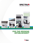
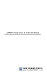
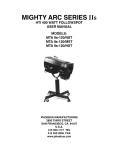
Desoldering: It’s easier than you think! ==================================================================== De-Soldering / Soldering Kit User’s Manual © Copyright 2002 R.S.R. Electronics, Inc. All rights reserved. Ver. 2 0708 Introduction: Desoldering 1.0 Equipment Two essential things are required to desolder a component: a good soldering iron something to remove solder Safety Goggles Since hot, melted solder can "splatter" a bit during removal, a good pair of safety goggles is strongly recommended. And, of course, you will need some hand tools such as long-nose pliers and "picks". Part No. 060370 1.1 Soldering Irons The job of the soldering iron is to melt the solder so that it can be removed. So called "pencil" irons in the 15 to 35 Watt range are good for most electronics printed circuit board work. Anything higher in wattage and you risk damaging either the component or the board. Tips for these irons come in various shapes. Which one you use is a personal preference. RSR 3-Wire Soldering Iron Part No. 060501 Note that you should never use soldering "guns". They are high-power (100 Watts or more) and generate heat by passing AC current through a loop-shaped tip. Besides the excessive heat, they can induce large AC currents into stray loops on the board. 1.2 Solder Removers There are three common ways to remove solder: copper braid (usually called "solder wick") hand-operated suction devices (spring-loaded "solder-suckers" or rubber "squeeze-bulbs") power suction devices (motor driven, like a vacuum machine) 1.2.1 Desolder Wick Desolder wick is fine copper braid sometimes containing a small amount of rosin flux. Desolder wick will “wick up” molten solder much like a towel will pick up water. To remove solder from a joint, the joint is heated. Then the desoldering braid is applied to the joint.The solder is drawn into the braid, so leaving the joint relatively solder-free. The desolder wick is gentle on circuit boards, and can get into small places. It is an essential part of a desoldering tool kit. Desoldering Wick Part No. 060800 1.2.2 Hand-Operated Solder Removers Hand operated solder removers, often called "solder suckers", are an essential tool for desoldering work. They can usually be operated with one hand. Pressing in the plunger forces air out of a cylinder. The plunger is kept pressed by a latch. When a button on the side of the tool is pressed, a spring forces the plunger back out at high speed. That causes a temporary vacuum that will suck melted solder off the board. They can be very useful for removing solder from the pins of ICs and other devices. Desolder Pump Part No. 0608RD7382 1 Because of the force of the vacuum, solder suckers can also pull the copper pads off the circuit board. Small pads on single-sided boards with non-plated-through holes are especially liable to be pulled off a board. CMOS devices might need a pump which is Electro-Static Discharge (ESD) safe. Also, the nozzle tips will need replacing occasionally. Another popular hand-operated suction tool is the simple rubber bulb shown here. Its advantage is that the amount of suction can be controlled by squeezing the bulb more or less. It can also be used to blow melted solder out of a hole Desoldering Bulb Part No. 060825 With both the spring activated solder sucker and the rubber bulb sucker, eventually solder will build up around the tip and also inside the unit. So periodically they must be disassembled and cleaned out. Note that during disassembly your fingers and hands will probably become covered with the fine solder dust that the tools contain. Be sure to wash your hands thoroughly to remove that powder before eating. Both the spring-loaded solder-sucker and the rubber bulb sucker can be obtained mounted on a soldering iron for one-hand operation. Electric Desoldering Tool Desoldering Iron Part No. 060848 Part No. 060849 1.2.3 Powered Solder Removers The ultimate in desoldering technology is a vacuum powered piece of equipment as shown below. While more expensive than the tools shown above, a powered unit can be a worth-while investment for any shop that does a large amount of desoldering on an on-going basis. For occasional desoldering, such a unit would be "over-kill". Desoldering Station Part No. 0608968ESD 2.0 Technique 2.1 Preparing the Surface Remove any dirt, grease, varnish, epoxy, or glue off the solder joint before you start heating. Otherwise, you can foul the tip of your soldering iron pretty quickly. 2.2 Applying Heat Place the tip of the soldering iron against both the component lead and the board. Place it firmly, but do not push too hard or you will damage the tip of your iron and perhaps the component as well. Normally, it takes only two or three seconds to melt the solder, but larger components can require more time. Sometimes it is necessary to apply a small amount of solder to "wet" the solder you wish to remove in order to transfer enough heat to melt it. 2 2.3 Removing Solder 2.3.1 Using Solder Wick Lay the wick over the solder joint and put the tip of the iron onto the wick. Press down firmly but not too hard. When the wick is hot enough, the solder will melt and the wick will soak it up. When a section of wick is filled with solder, cut it off and pull some more off the spool. Take care that you don't allow the solder to cool with the braid adhering to the work, or you damage the copper traces when you attempt to pull the braid off the joint. Caution: copper conducts heat very well; don't burn your fingers on the braid! 2.3.2 Using a Solder Sucker Push down the plunger so it locks into place. Usually, you will feel or hear a click. If the tool has been used before, a small "plug" of solder may be pushed out of the nozzle. If so, remove it. Once the solder sucker is cocked, put the nozzle over the molten solder and press the button. The plunger will pop up quickly taking the solder with it. This should remove most, if not all, the solder from the joint. You may need to repeat this step a few times in order to get all the solder. 2.3.3 Cleaning Up and Touching Up You may wish to remove any resin and left over solder from the circuit board and/or component. There are commercial products available to take off the resin, but 000 steel wool works well of you are careful. Solder wick can be used to "touch up" any remaining solder. 2.3.4 Reusing a Damaged Circuit Board If you wish to reuse the circuit board, then you must repair any damage caused by desoldering. Occasionally, you may lift a pad from the board without breaking the traces. If so, then it should be ok to just leave it; a replacement part can hold the pad in place. If you actually break a trace, you will need to use a small piece of wire to connect the pad to where it is supposed to go. Follow the trace until you find a suitable location for soldering, usually the next closest solder joint. Then, solder the wire between the two points. You can use a multi-meter set to Ohms to check continuity of traces after you removing components. 3.0 Tips and Suggestions Heatsinks. If you use a low-wattage iron, then usually heatsinks are not required as long as you melt and remove the solder quickly. If you expect the desoldering of a component to take a long time, you can use a clip-on heat-sink. But usually a pair of long-nose or needle-nose pliers is all you need. Keep the iron tip clean. A clean iron tip means better heat conduction. Use a damp (not soaking wet) sponge or cloth to clean the tip from time to time as you work. Use both a solder sucker and solder wick. Use a solder sucker to remove the majority of the solder, then follow up with the wick to remove what's left Other tools. You can use dental picks or specially designed tools to help free wires and components from the melted solder. Solder Aid Kit Part No. 060830 3 4.0 Tutorial: How to Desolder You will use the RSR Desoldering Practice Board to develop a valuable and necessary skill-set for the Electronics Technician: the desoldering and removing of components from a printed circuit board (pcb). This manual is designed to be a tutorial and a hands-on application. As the name implies, desoldering (or desoldering) a component is the opposite of soldering a component into place. There are several reasons why we may want to desolder a component: Component Repair: we need to remove a defective component and replace it with a good one. Fixing Bad Solder Joints: sometimes the solder connections on a component are "bad", causing intermittent failure or noise. It may be necessary to remove the old solder and replace it with new solder. A poorly soldered joint is often called a "dry joint". Usually dirt or grease prevented the solder from melting onto the parts properly, as indicated by the solder not spreading out. The solder will look like beads or globules. Salvage: we wish to save some expensive and/or hard to get components from an assembly that is being scrapped. After completing the steps in the procedure below, not only will you have gained new skills, you will also have a stock of electronics components you can use to build breadboards and prototypes of your own circuits. 4.1 Safety Information Solder is an alloy, usually of tin and lead which is melted to join other metal surfaces. Wash hands thoroughly with soap and water after handling solder, and especially before eating or smoking. Most soldering and desoldering irons or tools work at around 250ºC or 480ºF. Care should be taken while handling these tools. Solder on a fire resistant surface. Never leave your iton plugged in and unattended. Never set your hot iron down on anything other than an iron stand. Flux is a sticky liquid or paste used to react with and remove compounds from the surface of the connection, to improve flow of the molten solder, and to prevent oxidation during the heating cycle. Flux tends to spit when hot. So always wear some form of eye protection like goggles or face shield when soldering. When heated during soldering, rosin fluxes give off fumes containing many chemical compounds. These can cause irritation, occupational asthma, birth defects, and other health problems including cancer. If you are pregnant, or considering it, you should consult with your doctor before using lead or solder. Solder/Desolder only in a well ventilated area, and use an exhaust device that moves solder fumes away from your face. It’s preferable to exhaust outside (check local/state building codes and restrictions on venting to outside air). If you do not exhaust to the outside, use a bench top fan or intake device with a replaceable smoke/fume absorber. The filter should be activated charcoal. When ventilation is not sufficient, an OSHA approved respirator available for fumes should be worn. Fume Absorber – Bench Top Part No. 060860 The above information is for guidance only and user must refer to the Material Safety Data Sheet relevant to solder and desolder wick before use. 4 4.2 Procedure Step 1: Power Transistor Q3 Identify TO-220 transistor and remove the screw attached to the heat-sink. Remove Q3. Step 2: Heat-sink Identify heat-sink and remove. Step 3: Buzzer Identify buzzer BZ1. Notice that buzzer is mounted on the underside of board. form the top of board and remove. De-solder Step 4: Power Connectors Identify power connectors J1 and J2 and remove. Step 5: Power Transistor Q2 Identify power transistor Q2 and remove the screw. It might be helpful to straighten the pins before removal. To help you become familiar with the resistor color code you can print a free copy at http://www.elexp.com/t_resist.htm Step 6: Large Power Resistors, 0.10 Ohms (BLK BRN BLK SIL) Identify and remove large power resistors R1 and R6. Note: On a 5-BAND-CODE as shown on the resistor color guide, the fourth band is the multiplier. Step 7: Transistors Q1 and Q2 Identify transistors Q1 and Q2 and remove. Step 8: LEDs D1 and D2 Identify regular LEDS D1and D2 and remove. Step 9: Bipolar LEDs (Two LEDs in one package) D3 and D4 Identify bipolar LEDs D3 and D4 and remove. Step 10: Ceramic Disk Capacitors, 100,000 pF (104) Identify and remove all the 0.1uF disk capacitors. How many did you remove? Step 11: 470 Resistors (YEL PUR BRN) Identify and remove all 470 resistors. How many did you remove? Step 12: 24 K (24,000 Ohm) Resistor Identify and remove the 24 K resistor. What colors are on them? Step 13: 10 K (10,000 Ohm) Resistors (BRN BLK ORA) Identify and remove all 10 K resistors. How many did you remove? Step 14: 2 K (2,000 Ohm) Resistors Identify and remove all 2 K resistors. How many did you remove? What colors are on them? 5 Step 15: 1 K (1,000 Ohm) Resistors (BRN BLK RED) Identify and remove all 1 K resistors. How many did you remove? The next four resistors are 5-BAND-CODE resistors with the fourth band the MULTIPLER and the fifth band the TOLERANCE. Step 16: 476 K (476,000 Ohm) Resistor (YEL PUR GRE ORA) Find and remove the 476 K resistor. What is its designation on the pc board? Step 17: 392 K (392,000 Ohm) Resistor (ORA WHI RED RED) Find and remove the 392 K resistor. What is its designation on the pc board? Step 18: 10 K (10,000 Ohm) Resistor (BRN BLK BLK RED) Find and remove the 10 K resistor. What is its designation on the pc board? Step 19: R11 (ORA BLK BRN ORA) Find and remove R11. What value is it? Step 20: Diode D5 Identify and remove D5. Step 21: Integrated Circuits (ICs): U3, U4, U5 Locate and remove the ICs. See if you can identify them on-line via the internet at http://www.datasheetarchive.com/. What are their descriptions? IC U3 Generic Type HA17324 or LM324 U4 U5 HA17339 or LM339 PIC16F627-40/P Description Step 22: Contact Switches S1 and S2 Identify and carefully remove the tape from the switches. The switches are not soldered so removal will be easy. Step 23: Board Examination Examine the stripped board to see how many (if any) pad and traces have been damaged. 6 5.0 Soldering Good soldering results depend on a few but important steps to follow as outlined below. 5.1 Pre-heat the soldering iron for approximately five minutes, tin the tip, and roll the tip on a moistened sponge until it appears bright and shiny. Brush the soldering iron tip on the moistened sponge prior to each use to remove burnt rosin and to ensure proper heat transfer. 5.2 Place the pre-heated, tinned, soldering iron tip, simultaneously, against the printed circuit board foil and the component lead for approximately three to five seconds as in Figure 1 below. Figure 1 5.3. Apply solder to the component lead opposite the soldering iron and permit the solder to melt evenly around the connection as indicated in Figure 2. Do not apply solder directly to the soldering iron tip. Figure 2 5.4 Next remove the solder and then remove the soldering iron. This sequence is important as reversing it may result in a cold solder joint. Permit the joint to cool before attempting to move the part or otherwise stressing the joint. 5.5 The soldering joint when properly soldered should appear bright and uniform with an even miniscus as indicated in Figure 3 below. Figure 3 7