1
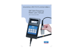
SKF Belt Frequency
Meter user manual
User manual box edition
General safety tips
Table of contents
Safety first – read and understand this manual before
operating the SKF Belt Frequency Meter.
Never use your SKF Belt Frequency Meter on moving belts.
page
1.0 Device description
4
2.0 Quick start
5
3.0 Functions
Switch off and isolate any
belt drive system prior to
taking tension measurements
or attempting any other
installation work.
Do not drop the meter or
subject either the meter or
the optical sensor to other
sharp impact.
Do not put water, solvents
(including cleaning solutions)
or any other liquid on the
unit. Clean meter and
sensor with dry cotton cloth.
Do not pull on sensor cable.
Disconnect sensor from
meter by grasping the
connector grip only.
Do not leave the unit in
places that are humid, hot,
dust filled or in direct
sunlight.
Hint: When SKF Belt
Frequency Meter is not used
for a while, remove batteries
and store unit in the case
provided.
3.1 Keys
6
3.2 Audio/ visual display
7
3.3 Optical sensor
8
3.4 Battery condition
9
3.5 Charging batteries
10
4.0 Setup & use
11
5.0 Operating tips
13
Do not use your SKF Belt
Frequency Meter in any
potentially explosive
environment.
6.0 Meter range
14
7.1 Spot check
15
Do not disassemble or
attempt to modify either the
meter or the sensing head.
7.2 Annual certification
16
8.0 Technical specification
17
9.0 Useful formulae and conversions
18
7.0 Calibration
Appendix
Local language versions of this manual can
be downloaded from www.skfptp.com/bfm
1.0 Theory of operation
19
2.0 Limited warranty
20
3.0 Belt mass constants
21
1.0 Device description
2.0 Quick start
The SKF Belt Frequency Meter is a two component system consisting of a hand-held meter
attached to an optical sensor via an electronic cable. The sensor uses an infrared beam to detect
the vibration of a belt strand and sends a signal to the meter. (The sensor includes an LED that
produces an orange light beam to help aim the invisible infrared ray.) Comparing this input to
the vibration of a quartz crystal, the meter computes the natural frequency of the belt. The result
is shown in the display window as hertz (oscillations per second). The internal programming of
the meter is also able to report the belt tension in units of force (either newton or pounds-force)
provided the operator has entered the belt mass and span length using the manually operated
key pad.
5. Read belt
frequency (Hz)
The meter operates on four “AA” batteries. Battery life is approximately 20 hours. The battery
compartment is accessible at the back of the meter. This manual, a tuning fork for checking
calibration and a storage case are included with the complete kit.
LED aiming
beam
2. Press
to switch
meter on
Display
window see
section 3.2
Keypad see
section 3.1
4. Tap or
pluck belt
1. Plug in sensor
3. Aim sensor at belt, gap
5 to 25 mm
Optical sensor
see section 3.3
4
Plug in
sensor cable
5
3.0 Functions
3.1 Keys
ON/OFF
SPAN
(m)
MASS
(kg/m)
This key switches the meter on or off. If the meter is on and sits idle for more
than 3 minutes, it automatically switches off to preserve battery life. When the
meter is first switched on a battery check is made. See Section 3.4 for a description
of the visual and audible low battery signal.
This key is used to enter the belt span length. The span key is held down while
the UP or DOWN keys are used to set the belt span in metres. Releasing the
SPAN key results in an audible beep to indicate the setting has been accepted.
Pressing the SPAN key alone, shows the current setting.
This key is used to enter the belt mass. The mass key is held down while the
UP or DOWN keys are used to set the belt mass in kg/m. Releasing the MASS
key results in an audible beep to indicate the setting has been accepted. Pressing
the MASS key alone shows the current setting.
3.2 Audio/visual display
The SKF Belt Frequency Meter is an interactive tool. It provides both visual and audible
communication with the operator. Each signal or combination of signals has a meaning. While
all these signals are discussed in other sections of this manual, a compilation of all the available
signals will be presented here.
Generally visual signals alone give measurement results while audible signals, either alone or in
combination with a visual signal, indicate some operational step.
Frequency mode,
results displayed as hertz
N
Hz
lbs
N
Hz
lbs
Tension displayed
in newton
N
Hz
lbs
Tension displayed
in pound-force.
Visual measurement
results
A line segment will appear to indicate the
units assocaited with the number displayed
Important Note:
Belt span and belt mass are required entries if tension results in force units (N or lbf)
are desired. Entries must be in SI units (m and kg/m)
UP
(Hz/N)
DOWN
(Lbs)
MEM 1
MEM 2
MEM 3
6
This key has two functions. The first is to increase either the SPAN or MASS
parameters when used in conjunction with these keys. The second use is to
toggle between the Hz and the newton measurement modes.
This key has two functions. The first is to decrease either the SPAN or MASS
parameters when used in conjunction with those keys. The second use is to
toggle between the Hz and the pound measurement modes.
The memory keys allow up to 3 sets of belt parameters to be stored in the
meter registry. Pressing the MEM 1 key recalls the first set of belt parameters
and likewise for MEM 2 and MEM 3.
To store the belt parameters to a key, the belt span and mass parameters must
first be entered and then immediately after release of either the SPAN or MASS
keys the appropriate MEM key should be pressed. Two beeps indicate that the
parameters have been successfully assigned to the key.
Audible signals
Signal
When
Means
One Beep
Upon release of “Span” key
Input accepted
One Beep
Upon release of “Mass” key
Input accepted
One Beep
While sensor is aimed at vibrating belt
Measurement taken
Two Beeps
Upon pushing “Memory” key after
releasing “Span” key
Span data has been stored
Upon pushing “Memory” key after
releasing 'Mass' key
Mass data has been stored
Four Beeps
Combined with “0000” N display
Newton result is out of range
Combined with “0000” lb display
Pound result is out of range
After pushing “On” key combined with
“zero” countdown
Low battery condition
7
3.3 Optical sensor
3.4 Battery condition
The sensor uses an invisible infrared beam to
detect vibrations of the belt. A narrow angle
orange LED generated beam is provided to guide
the aiming of the sensor.
When the SKF Belt Frequency Meter is first switched on, a battery condition check is automatically
performed. A low battery condition is signalled both visually and audibly. The display window will
flash an array of zeros, starting with four and progressing to only one. There will be an audible
signal of four “beeps” as the display changes
The very best signal from the belt is seen when
the sensor is held perpendicular to the belt at the
centre of the span at 9,5 mm (3/8 in) distance.
When physical restrictions are present, it is
possible to get useable readings with the sensor
up to 50 mm (2 in) distance from the belt and/or
tipped up to 45° from perpendicular.
N
Hz
lbs
BEEP
It is possible to take measurements from the
edge of the belt. The toothed side of a belt is
equally acceptable as a target for the sensor.
The sensor LEDs should be kept clean by wiping
with a soft cotton cloth. Solvents are never to
be used.
N
Hz
lbs
BEEP
N
Hz
lbs
BEEP
N
Hz
lbs
BEEP
If these signals are seen and heard, batteries should be replaced. Batteries are accessed through
the removable cover on the back of the meter. New batteries should be inserted within 30
seconds of removal of old batteries. Taking longer risks loss of any data stored by the memory
keys. Batteries are expected to provide approximately 20 hours of continuous operation before
replacement is required.
8
9
4.0 Setup and use procedure
3.5 Charging batteries
Do not charge batteries with the sensor head attached to the meter. Do not attempt to use the
meter while batteries are being charged. Damage to the optical sensor could result.
1. Plug sensor head into meter body. This is a keyed
plug. Line it up, do not use force!
The SKF Belt Frequency Meter is compatible with user supplied rechargeable batteries and
charging unit. A convenient 3,5 mm, positive centre charging socket is located on the bottom end
of the meter body adjacent to the sensor cable plug-in port.
Batteries:
1 300 mAh minimum (user supplied)
Charging unit: 12 to 15 volt DC output (user supplied)
Connection:
3,5 mm positive tip mini plug/socket
The built in circuit of the meter controls the charging current. Charging current is internally
limited to 100 mA. Charging time is typically 12 to 14 hours for a full charge.
You may turn the unit on while charging. The meter’s software will then signal that the batteries
are charging. The display window will flash an array of zeros, starting with only one and
progressing to four. There will be an audible signal of four 'beeps' as the display charges.
2. Turn unit on using
Suitable rechargeable batteries and charger may be obtained directly from IDS.
3. Load span and mass data or recall previously loaded data.
ON/OFF
.
To load span data simply hold down
UP
(Hz/N)
or
DOWN
(Lbs)
SPAN
(m)
while using
to set the number.
When the correct number appears in the display window, simply release the span key.
The unit will beep once to acknowledge acceptance of this setting.
To load mass data simply hold down
UP
(Hz/N)
or
DOWN
(Lbs)
MASS
(kg/m)
while using
to set the number.
When the correct number appears in the display window, simply release the mass key.
The unit will beep once to acknowledge acceptance of this setting.
To save individual entries into memory, press appropriate key
MEM 1
,
MEM 2
or
MEM 3
.
As soon as the span or mass keys have been released, the meter will beep twice to
acknowledge the entry into memory.
10
11
5.0 Operating tips
To recall stored data in working memory simply press
MEM 1
,
MEM 2
or
MEM 3
, depending
upon where you stored the data for this specific drive. Afterwards press span or mass key in
order to display the appropriate saved value (mass or span).
4. Aim sensor at centre of selected belt span.
Tap or pluck the belt. The meter will beep
once to indicate that a measurement was taken.
Here are some procedures and “best” practices that may ease use or help increase the reliability
of your belt tensioning efforts.
Take your tension reading as close to the centre of the selected span as practical.
Use the longest belt span that can be readily accessed. Minimum useable span length is equal
to 20 times the belt tooth pitch for synchronous belts and 30 times the belt top width for “v”
configuration belts. Using too short a span yields indicated tensions that may be much higher
than actual belt tension due to effects of belt stiffness.
Where possible, orientate the sensor head with the long edge of the sensor parallel to the
centre-line of the belt. This tends to eliminate any non-reading conditions due to aiming error.
Gap 10
to 50 mm
On new installations, rotate the system by hand at least one full revolution of the belt to seat
and normalise the components.
If the top surface of the belt is not accessible, try to beam the sensor against the edge of the belt.
The inside surface of the belt is equally acceptable.
The meter will not give a measurement for a belt under extremely low tension. Simply increase
the drive tensioning until the meter responds. The meter will beep to indicate that a reading has
been taken.
5. Display window will show frequency result.
N
Hz
lbs
6. Press
UP
(Hz/N)
to toggle to newton.
N
Hz
lbs
7. Press
DOWN
(Lbs)
to toggle to pounds.
N
Hz
lbs
Note: Pressing the same key a second time will return display to the hertz value.
It is good practice to take three successive readings. This will show the consistency of your
methods. If the readings vary by more than 10% reassess your measurement technique.
Taking multiple readings at different belt orientations may help you identify problems with other
drive components. Tension excursions are indicative of component problems such as a bent shaft,
poorly mounted sprocket or pulley or an irregular pulley groove.
When tensioning an array of multiple V-belts, use a single belt toward the centre of the array.
Please, also check the tension of the belts on each side of the array in order to secure that there
is no angular misalignment between the pulleys.
8. Re-adjust belt tension and repeat measurement until target tension results are attained.
12
13
6.0 Meter range
7.0 Calibration
7.1 Spot check
The SKF Belt Frequency Meter is capable of
measuring belt vibration frequencies between
10 Hz and 400 Hz.
If the measured frequency is below 10 Hz,
the meter will display “10.00” briefly and
then change to “000.0”.
If the measured frequency is above 400 Hz,
the meter will display “400” briefly and
then change to “000”.
N
Hz
lbs
BEEP
BEEP
BEEP
BEEP
N
Hz
lbs
A '0000' newton reading
accompanied by four
'beeps' indicates the
result is out of range
BEEP
A '0000' pound reading
accompanied by four
'beeps' indicates the
result is out of range
BEEP
BEEP
BEEP
On multi-shaft (three or more shafts) it may be possible to get valid measurements by selecting a
different belt span for measurement. If the measured frequency is below 10 Hz choose an available shorter span. If the measured frequency is above 400 Hz choose a longer span if available.
Based upon the measured belt frequency, the meter is capable of calculating belt tensions up
to 9 990 N (2 200 lb.). When these limits are exceeded the meter will react as previously
described.
Belt tensions greater than these values are unusual. It is therefore advisable to check that the
span and mass parameters have been entered correctly. If they are found to be correct then
check the calculation of your target values. If everything looks correct then this drive is simply
beyond the capacity of the SKF Belt Frequency Meter. The drive will have to be tensioned by
traditional force and deflection techniques.
Special Note:
Tensioning a drive generally involves moving one component shaft with respect to another.
On some drives, especially larger installations, tensioning the drive will involve sufficient movement that the span length is appreciably altered. Frequency (Hz) values will remain accurate but if
a precise tension value is to be calculated it may become necessary to update the span input to
reflect the new shaft spacing.
14
The measurement system of the SKF Belt Frequency Meter is based upon a very stable quartz
crystal that should never wander. However, a precision mechanical resonator (tuning fork) is
included with the meter so that a calibration check at a spot frequency of 250 Hz may be
performed at any time.
Tap the tip of the tuning
fork on a hard surface
and then hold STEADY
in front of the optical
sensor at a distance
of 10 to 15 mm. The
meter will measure a
frequency of 250 Hz
thus demonstrating
that it is in calibration.
Results within ±1% are acceptable. There is no adjustment possible. If greater variance is
experienced, the meter should be returned for calibration. See section 7.2 for manufacturer’s
contact information.
15
8.0 Technical specification
7.2 Annual certification
Technical support relating to calibration certification and/or operation of the SKF Belt Frequency
Meter can be obtained from the manufacturer at:
[email protected]
phone: +44 191 262 7869
fax:
+44 191 262 0091
The meter may be returned to the manufacturer for repair or recalibration at any time.
A factory calibration certificate is included with each meter. Although the very stable solid-state
quartz crystal based system is not likely to go out of calibration, some operating procedures call
for annual gauge certification. For certification/calibration purposes the meter may be returned
to the manufacturer at yearly intervals to have the meter recalibrated and certified to NAMAS/
UKAS (National Accreditation of Measurement and Sampling/United Kingdom Accreditation
Standards) standards.
The manufacturer must be contacted for detailed costs and shipping procedures prior to any
return. Contact information for Integrated Display Systems Limited (IDS) is shown in Appendix 2.
There will be a charge for these services.
Measurement range
Frequency range .................................. 10 to 400 Hz
Measurement accuracy
Below 100 Hz............................... ± 1 significant digit
Above 100 Hz................................ ± 1%
Belt mass input range .......................... 0,001 to 9,990 kg/m
Belt span input range .......................... 0,001 to 9,99 m
Maximum belt tension display ............ 9 990 N
2 200 lb
Environmental conditions
Operating temperature ........................ +10 to +50 °C
Shipment and storage temp ............... −40 to +70 °C
Protection class...................................... IP54
Sensor
Type.......................................................... Infrared optical
IR wavelength......................................... 970 nm
Visible aiming beam.............................. Narrow angle orange LED
Housing .................................................. Machined aluminium
Cable length ........................................... 1 m
Power supply
Battery type............................................ AA (MN1500) Alkaline only
Number .................................................. 4
Expected life............................................ 20 hrs
Compartment location ..........................Back of meter
Optional rechargeable batteries
Battery type............................................ AA (1 300 mAh minimum)
Charger.................................................... 12 to 15 V DC output
Socket/polarity........................................ 3,5 mm positive centre
16
17
9.0 Formulae and conversions
Appendix
1.0 Theory of operation
Force conversion constants
newton x 0,2248 = lb
pound x 4,4482 = N
kilogram x 9,8067 = N
Length conversion constants
inch x 0,0254 = m
metre x 39,3701 = in
mm x 0,001 = m
Span length calculation
S=
CD2 -
(D - d)2
4
where:
S = Span length (mm)
CD = Centre distance (mm)
D = Large pulley diameter (mm)
d = Small pulley diameter (mm)
There is a direct relationship between belt tension and a belt’s natural frequency of vibration.
As the tension is increased, the vibration frequency also increases. The relationship between
tension and frequency has been determined to be:
T = 4ml 2 f 2
Where
T = Belt tension (N)
m= mass per unit length (kg/m)
l = span length (m)
f = vibration frequency (Hz)
The SKF Belt Frequency Meter is a dual function tool. The optical sensing head uses an invisible
infrared beam to detect vibration while the integral calculator determines the time base and
performs the necessary calculations to support the results shown in the display window.
The meter may be used with all power transmission belts regardless of type or construction.
Weight (for mass calculation use)
ounce x 0,02835 = kg
pound x 0,45359 = kg
Reminder: Belt span and mass inputs to the meter must be in SI units, m for the belt span
and kg/m for the belt mass.
18
19
2.0 Limited Warranty
Limited Warranty Time of warranty is 12 months from date of original purchase provided that
proper product registration has been completed. Product registration may be completed online
at; www.clavis.co.uk/skfbeltmeter
Warranty covers defects in materials and workmanship for the device only. Warranty does not
cover accessory items such as batteries and applies only to parts that were not damaged as a
result of inappropriate handling or use. The warranty expires immediately if the device itself
is opened. Unit must be returned to Integrated Display Systems Ltd (IDS) for evaluation of all
warranty claims. Any SKF Belt Frequency Meter claimed to have a covered warranty condition
involving material or workmanship shall, upon IDS’s approval, be returned to IDS as designated,
at the Customer’s expense. Under no circumstances will liability exceed the original purchase
price of the meter. IDS reserves the right to repair or replace the unit or to refund the original
purchase price at their sole option.
3.0 Weights and tension values
Timing belts
Belt type
Contact IDS Customer Service for warranty claims, product return procedure or technical
information.
Integrated Display Systems Limited (IDS)
Tel: +44 (0) 191 262 7869 Fax: +44 (0) 191 262 0091 www.clavis.co.uk
Information you will need to register warranty online (keep log for your records)
Date of Purchase
Serial Number (on back of unit)
Purchaser’s Name
Purchaser’s Mailing Address
Belt Tension
New belt
Run in belt
Mass
N
N
kg/m
HiTD
5M 9
5M 15
5M 25
8M 20
8M 30
8M 50
8M 85
14M 40
14M 55
14M 85
14M 115
14M 170
99
174
311
372
593
1 037
2 044
1 297
1 912
3 142
4 480
7 139
71
124
222
266
424
741
1 460
926
1 366
2 244
3 200
5 099
0,037
0,061
0,102
0,128
0,192
0,320
0,545
0,429
0,590
0,911
1,233
1,823
STPD
S8M20
S8M30
S8M50
S8M85
S14M40
S14M55
S14M85
S14M115
S14M170
390
620
1 110
2 030
1 340
1 925
3 165
4 465
6 975
279
443
793
1 450
957
1 375
2 261
3 189
4 982
0,111
0,167
0,278
0,473
0,462
0,634
0,981
1,327
1,962
Timing belts
XL 025
XL 037
LO50
LO75
L 100
H075
H100
H150
H200
H300
XH 200
XH 300
XH 400
XXH 200
XXH 300
XXH 400
13
24
51
87
122
220
311
485
667
1 045
907
1 428
2 019
1 130
1 748
2 478
11
20
41
70
98
176
249
388
534
836
726
1 142
1 615
904
1 398
1 982
0,014
0,020
0,043
0,065
0,087
0,084
0,112
0,168
0,223
0,335
0,572
0,858
1,144
0,809
1,213
1,617
Limitation of Warranty: IDS excludes any further liability for software, handbooks and information
material. Furthermore, IDS does not accept liability for damages resulting from the use of the
SKF Belt Frequency Meter.
IDS’s total responsibility and liability for any and all claims, losses and damages of any kind
whatsoever arising out of any cause whatsoever (whether under any warranty or based contract,
negligence, other tort, strict liability, breach of warranty, other theory or otherwise) shall not
exceed the original purchase price of the SKF Belt Frequency Meter in respect to which such
cause arise, and in no event shall IDS be liable for special, incidental, consequential, exemplary,
or punitive damages resulting from any such cause. No employee, agent and/or representative,
promise or agreement, except as stated herein. IDS shall not be liable for, and customer assumes
all liability for, all personal injury and property damage connected with the use of the product.
There are no warranties which extend beyond the description on the face hereof, and IDS
disclaims warranty of fitness for purpose or any other implied warranties.
Belt type
E-mail (optional)
Purchased from
20
21
Wrapped V, wedge and banded belts
Belt
type
Smallest pulley
diameter
Speed range
over
over
incl.
mm
Z
40
B
C
D
SPZ
60
75
90
90
120
120
175
105
140
140
220
175
230
230
400
305
400
400
510
56
79
79
95
95 over
SPA
71
105
105
140
140 over
SPB
107
159
159
250
250 over
22
incl.
rpm
60 over
A
Wrapped V, wedge and banded belts
Belt tension per
single belt*
New belt
Run in belt
Mass
N
N
kg/m
Single belt Belt in a
band**
1 000
2 500
1 000
2 500
2 500
4 000
2 500
4 000
104
121
174
174
69
81
116
116
0,060
1 000
2 500
1 000
2 500
1 000
2 500
2 500
4 000
2 500
4 000
2 500
4 000
332
254
391
332
469
411
222
169
261
222
313
274
0,108
860
2 500
860
2 500
2 500
4 000
2 500
4 000
469
391
567
528
313
261
378
352
0,187
Belt
type
Smallest pulley
diameter
Speed range
over
over
incl.
mm
n/a
SPC
200
rpm
355
355 over
0,150
3V
5V
0,260
8V
500
1 740
500
1 740
1 740
3 000
1 740
3 000
1 017
841
1 251
1 115
678
561
834
743
0,310
0,417
200
850
200
850
850
1 500
850
1 500
2 210
1 877
2 698
2 268
1 473
1 251
1 799
1 512
0,635
0,870
1 000
2 500
1 000
2 500
1 000
2 500
2 500
4 000
2 500
4 000
2 500
4 000
338
262
383
415
477
438
226
175
255
276
318
292
0,079
n/a
1 000
2 500
1 000
2 500
1 000
2 500
2 500
4 000
2 500
4 000
2 500
4 000
575
524
696
628
872
876
383
349
464
418
581
584
0,134
860
2 500
860
2 500
860
2 500
2 500
4 000
2 500
4 000
2 500
4 000
978
941
1 255
1 116
1 496
1 275
652
627
837
744
997
850
0,208
61
90
90
175
171
275
275
500
315
430
430
570
Mass
N
N
kg/m
Single belt Belt in a
band**
500
1 740
500
1 740
1 740
3 000
1 740
3 000
2 026
2 043
2 305
2 671
1 350
1 362
1 537
1 781
0,380
0,440
1 000
2 500
1 000
2 500
2 500
4 000
2 500
4 000
313
274
430
391
209
182
287
261
0,076
0,102
500
1 740
500
1 740
1 740
3 000
1 740
3 000
1 134
997
1 369
1 291
756
665
912
860
0,223
0,272
200
850
200
850
850
1 500
850
1 500
2 933
2 386
3 520
3 129
1 955
1 590
2 346
2 086
0,545
0,616
* Multiply the belt tension required for a single belt by the number of the belts in the banded
belt unit to get total tension to apply.
** Multiply the mass of one belt in a band by the number of the belts in the banded belt unit to
get total mass to apply.
Cogged raw edge V, wedge and banded belts
Belt
type
Smallest pulley
diameter
Speed range
over
over
incl.
mm
0,155
ZX
40
AX
incl.
rpm
Belt tension per
single belt*
New belt
Run in belt
Mass
N
N
kg/m
Single belt Belt in a
band**
60
1 000
2 500
1 000
2 500
2 500
4 000
2 500
4 000
119
139
199
199
80
93
133
133
0,058
n/a
75
90
120
175
2 500
4 000
2 500
4 000
2 500
4 000
372
293
450
391
508
450
248
196
300
261
339
300
0,153
120
1 000
2 500
1 000
2 500
1 000
2 500
0,110
90
60 over
0,268
incl.
Belt tension per
single belt*
New belt
Run in belt
23
Cogged raw edge V, wedge and banded belts
Belt
type
Smallest pulley
diameter
Speed range
over
over
incl.
mm
BX
CX
XPZ
rpm
85
105
105
140
140
220
175
230
230
400
56
79
79
95
95 over
XPA
71
105
105
140
140 over
XPB
107
159
159
250
250 over
XPC
200
355
355 over
3VX
24
incl.
55
60
60
90
90
175
Cogged raw edge V, wedge and banded belts
Belt tension per
single belt*
New belt
Run in belt
Mass
N
N
kg/m
Single belt Belt in a
band**
Belt
type
Smallest pulley
diameter
Speed range
over
over
incl.
mm
860
2 500
860
2 500
860
2 500
2 500
4 000
2 500
4 000
2 500
4 000
430
372
626
547
763
645
287
248
417
365
508
430
0,180
0,225
500
1 740
500
1 740
1 740
3 000
1 740
3 000
1 310
1 056
1 408
1 291
873
704
939
860
0,329
0,398
1 000
2 500
1 000
2 500
1 000
2 500
2 500
4 000
2 500
4 000
2 500
4 000
362
299
438
418
499
469
241
199
292
279
332
313
0,068
n/a
1 000
2 500
1 000
2 500
1 000
2 500
2 500
4 000
2 500
4 000
2 500
4 000
657
598
796
718
997
897
438
399
531
478
665
598
0,127
0,156
860
2 500
860
2 500
860
2 500
2 500
4 000
2 500
4 000
2 500
4 000
1 116
1 075
1 435
1 330
1 596
1 455
744
717
957
886
1 064
970
0,232
500
1 740
500
1 740
1 740
3 000
1 740
3 000
2 313
2 333
2 632
3 050
1 542
1 555
1 755
2 034
0,347
1 000
2 500
1 000
2 500
1 000
2 500
2 500
4 000
2 500
4 000
2 500
4 000
293
254
372
332
469
430
196
169
248
222
313
287
0,065
5VX
0,548
0,102
rpm
110
170
170
275
275
400
1 000
2 500
500
1 740
500
1 740
2 500
4 000
1 740
3 001
1 740
3 001
Mass
N
N
kg/m
899
489
1 310
1 212
1 525
1 486
600
326
873
808
1 017
991
0,183
Single belt Belt in a
band**
0,252
* Multiply the belt tension required for a single belt by the number of the belts in the banded
belt unit to get total tension to apply.
** Multiply the mass of one belt in a band by the number of the belts in the banded belt unit to
get total mass to apply.
Ribbed belts
Belt
type
0,279
incl
Belt tension per
single belt*
New belt
Run in belt
Smallest pulley Speed range
diameter
Belt tension per one rib*
New belt
Run in belt
Mass**
Single belt
mm
rpm
N
N
kg/m
PJ
<80
>80
n/a
67
90
45
60
0,010
PK
<95
>95
n/a
139
178
93
119
0,018
PL
<150
>150
n/a
216
312
144
208
0,057
PM
<250
>250
n/a
672
912
448
608
0,120
* Multiply the belt tension required for one rib by the number of the ribs in the ribbed belt unit
to get total tension to apply.
** Multiply the mass of one rib by the number of the ribs in the ribbed belt to get total mass to
apply.
25
SKF GmbH
Gunnar Wester Str. 12,
97421 Schweinfurt
Germany
® SKF is a registered trademark of the SKF
Group
© SKF Group 2008
The contents of this publication are the
copyright of the publisher and may not be
reproduced (even extracts) unless permission
is granted. Every care has been taken to
ensure the accuracy of the information
contained in this publication but no liability can
be accepted for any loss or damage whether
direct, indirect or consequential arising out of
the use of the information contained herein.
Publication 6479 EN · January 2009
Local language versions of this manual can be
downloaded from www.skfptp.com/bfm
Printed in England on environmentally friendly
paper.