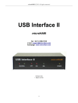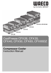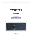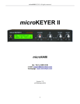
1
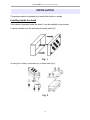
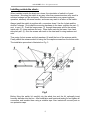
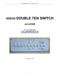
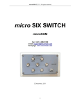
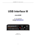
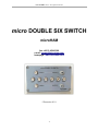
microHAM © 2011 All rights reserved
micro DOUBLE SIX SWITCH
microHAM
fax: +421 2 4594 5100
e-mail: [email protected]
homepage: www.microham.com
5 December 2011
1
microHAM © 2011 All rights reserved
TABLE OF CONTENTS
CHAPTER
1.
2.
3.
4.
5.
6.
7.
8.
9.
PAGE
IMPORTANT WARNINGS ......................................................................................... 3
DESCRIPTION .......................................................................................................... 3
CHARACTERISTICS AND FUNCTIONS ................................................................... 3
INSTALLATION ......................................................................................................... 5
CONFIGURATION ..................................................................................................... 8
TYPICAL PERFORMANCE .................................................................................... 10
PACKAGE CONTENTS ........................................................................................... 13
WARRANTY .............................................................................................................13
SPECIFICATIONS ................................................................................................... 14
2
microHAM © 2011 All rights reserved
IMPORTANT WARNINGS
Never operate the antenna switch with the case open
When installing at elevated site, always observe
proper safety precautions
Protect the inside of switch from humidity
DESCRIPTION
micro DOUBLE SIX SWITCH ("antenna switch") is a remotely operated antenna switch
(antenna relay). It can select six antennas to one of two common ports (output) and can
be installed either in the shack or on the tower.
CHARACTERISTICS AND FUNCTIONS
•
•
•
•
•
•
•
•
•
•
•
6 antenna positions enable use of separate antennas for up to six bands.
massive cast aluminum (wall thickness 4mm/0.158”) IP 66 class enclosure with
“O”-ring seal guarantees a high level of protection against weather and RF
interference
enclosed relays have insulation voltage of 10KV, contacts are of high silver
content alloy
microstrip PCB architecture with a compensated stub provides low SWR and
insertion loss in the range of 1.7 to 30 MHz
integrated surge protection
compatible with any band decoder with 12V source output
lid screws are secured against fallout
easily installable to wall or to tower using a massive fixture in the shape of double
C, enabling installation on tubes (tower legs) of various diameters
all antenna ports are grounded without power
all unselected antenna ports are grounded
two level interlock against connecting the same antenna to both outputs
3
microHAM © 2011 All rights reserved
INSTALLATION
The antenna switch is intended to be used either inside or outside.
Installing inside the shack
If the switch is operated inside the shack, it can be installed in any position.
It can be installed onto the wall using 4 screws (see Fig.1)
Fig. 1
or using the L-fixture, connectors up, or down (see Fig.2).
Fig. 2
4
microHAM © 2011 All rights reserved
Installing outside the shack :
When installed outside the shack on a tower, the orientation of switch is of great
importance. Mounting the switch in any way other than connectors down may result in
moisture leakage into the enclosure. Moisture accumulation may cause improper
operation, adversely influence function, and even may result in a failure of the switch.
Always install the switch in position with connectors down! Use the L-plate and the
double-C-clamps. First install the mounting hardware to the tower: position the part (1)
next to part (2) . Push the long screws (3) through these parts and fix the screws
inside part (2) using washers and nuts. Place these parts on the tower, from back
side push part (2) onto the screws with teeth to the mast and fix using washers and
nuts.
Then using 4 short screws and lock washers (4) install the box of the antenna switch.
Finally attach the antenna switch lid using the four captive screws from the bottom side.
The installation procedure is illustrated on Fig. 3.
Fig.3
Before fixing the switch lid, carefully dry the whole box and the lid, optionally insert
humidity absorber into the box. After installation and functional testing fix and tighten all
connectors and insulate them using a suitable tape. Also insulate all unused ports or
use protection caps.
5
microHAM © 2011 All rights reserved
Connecting the Switch:
micro DOUBLE SIX SWITCH connects directly to microHAM Station Master or other
band decoders and antenna selectors providing +12 to +16 volts to select an antenna.
Connect the top terminals B1 – B6 (shown at the right in figure 4 below) to the antenna
select outputs and the GND terminal to the ground or DC return terminal of the band
decoder or antenna controller for one radio. Connect the bottom terminals A1 - A6 to
the antenna select outputs and the GND terminal to the ground or DC return terminal of
the band decoder or antenna controller for the other radio.
Fig. 4
Configure your controller or band decoder to activate the appropriate output for the
desired antenna on each band. With some decoders it may be necessary to use
“summing diodes” or connect multiple outputs to a single control lead – for example
when using a multiband antenna.
If the micro DOUBLE SIX SWITCH is going to be placed outside, your band decoder
should have relay outputs or you should use an auxiliary relay driver board to protect
any decoder with solid state drivers. Remember, that the best protection is a galvanic
isolation with a high isolation voltage.
6
microHAM © 2011 All rights reserved
Cable length vs. Wire Size:
If antenna switch is located some distance from the decoder or controller, it is
necessary to use a cable of the appropriate length and wire size.
Cable length
[m] / [ft]
Conductor diameter
[mm]
Conductor Cross-section
[mm^2]
AWG
50 /150
0.4
0.14
26
100 /300
0.5
0.2
24
300 /1000
0.8
0.5
20
It is helpful (although not necessary) to use a shielded cable with the shield used as an
added ground lead to reduce voltage losses. Connect one end of the cable to the
terminals of antenna switch and solder the other end to an appropriate connector for
your controller or band decoder. micro DOUBLE Six Switch requires two cables with
seven conductors (six antennas plus return/ground); it is convenient to use shielded
CAT5/CAT6 cable and parallel the extra wire plus shield with the seventh (return)
conductor. Shielded CAT5/CAT6 with the extra return conductors will be more than
sufficient for 300 m /1000 ft.
CONFIGURATION
The antenna switch enables switching 6 antenna ports to either of two radio ports. The
basic configuration is such that each primary (contest) band from 160m to 10m has a
separate antenna port - port 1 for 160m, port 2 for 80m, etc.
The microHAM Band Decoder (discontinued) and microHAM Station Master (Port A)
have DB25 connectors for connecting an antenna switch. Typical connection are shown
in the following table :
Band
DB25M Antenna port
160
20
1
80
21
2
40
22
3
20
23
4
15
24
5
10
25
6
GND
18, 19
Table 2
7
microHAM © 2011 All rights reserved
If you have multiple antennas on one band, it will be necessary to select them using an
external switch. For example:
Band
Antennas
160
Dipole
80
Delta Loop, Inverted - V
40
XM-402
20, 15, 10
Tribander
30, 17, 12
WARC Tribander
Typical connecting cable with auxiliary switch:
Fig. 6
Assign Decoder outputs and connect antennas to the switch ports as shown:
Decoder Output
Antenna
Switch Port
160
Dipole
1
80
Delta Loop
2
80
Inv-V
3
40
XM-402
4
20, 15, 10
Tribander
5
30. 17. 17
WARC Tribander
6
An external two-position switch (or Band Decoder option) will be needed for 80 meters
in each cable. Station Master includes the option to select from among multiple
antennas per band.
8
microHAM © 2011 All rights reserved
Manual Control:
microDOUBLE SIX Switch is also usable without an automatic Band Decoder. In such case the
user will need to supply a manual 1 of 6 switch for each half of the switch. The design for such
a switch is shown at Figure 7.
Fig. 7
9
microHAM © 2011 All rights reserved
TYPICAL PERFORMANCE
The following figures show measurements on port 1. More detailed results for all ports
are available at www.microham.com
SWR :
Fig. 7
SWR is measured from the input to the selected antenna port.
10
microHAM © 2011 All rights reserved
Insertion loss :
Fig. 8
11
microHAM © 2011 All rights reserved
Isolation: (A to PORT 3, B to Port 5)
Fig. 9
Isolation is measured as the signal level at any unused port relative to the signal level
from the input with the selected port terminated in 50 ohms.
12
microHAM © 2011 All rights reserved
PACKAGE CONTENTS
The product includes micro DOUBLE SIX SWITCH and mounting bracket.
If the shipment is incomplete, please contact us at the following address:
E-mail:
[email protected]
fax :
+421 2 4594 5100
by Post:
microHAM s.r.o.
Nadrazna 36
90028 Ivanka pri Dunaji
SLOVAKIA
WARRANTY
microHAM warrants this product for three (3) years. The product must not be modified in any
way or the warranty is voided.
What is covered: During the warranty, microHAM, s.r.o., will repair or replace defective product
at their sole discretion. You must send the unit postpaid with a copy of the original invoice to the
distributor from whom you purchased the product. microHAM will pay return shipping.
What is not covered: This Limited Warranty does not cover (1) damage caused by misuse,
negligence, user modifications or failure to follow the user manual, (2) connection to improper
or excessive voltage or voltage surges, (3) the incorrect installation of any cables connected to
the device by the user, (4) weather related storm, lightning or electrostatic discharge damage,
or (5) damage due to switching with RF power applied (“hot” switching). .
microHAM assumes no liability or responsibility for damage to other devices or injuries to
persons as a consequence of using our products.
If the terms of the above warranty are not acceptable, return the unit, all associated documents
and accessories in the original unopened package, prepaid, to microHAM or to your supplier for
refund less shipping and a restocking fee.
13
microHAM © 2011 All rights reserved
SPECIFICATIONS
Frequency range : ......................................................................... 1,7 - 30 MHz
Characteristic impedance : .................................................................... 50 ohm
Number of antenna ports : ............................................................................. 6
Number of radio ports : .................................................................................. 2
Supply voltage : ..........................................................+12 to +16V DC to select
Consumption : ............................................................................... max. 180mA
Isolation voltage of relays : ......................................................................10KV
Connectors : ..................................... PTFE SO239 or N, depending on version
SWR: (typical) ......................................................................... 2 MHz < 1.03 : 1
30 MHz < 1.06 : 1
Insertion loss: (typical) ...........................................................2 MHz < 0.01 dB
30 MHz < 0.05 dB
Isolation: (depending on port) .............................................. 2 MHz: 80 - 115 dB
30 MHz: 60 - 90 dB
Guaranteed power rating :
SWR <1.3 :1 ............................................................................... 30 MHz < 5KW
SWR <2 : 1 ................................................................................. 30 MHz < 3KW
SWR <3 : 1 ................................................................................. 30 MHz < 2KW
Operating temperature range : ................................ -35 .. +70 C (-31.. 158 F)
Dimensions: ..................W 220mm (8,66") x H 103 mm (4") x D 120 mm (4.72")
Weight: ..............................................2,4 kg (5.29 lbs) + 1,1 kg (2.42 lbs) fixture
14