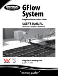
1
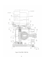
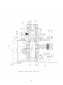
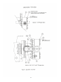
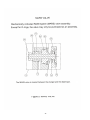
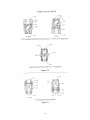
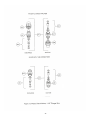
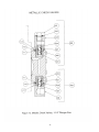
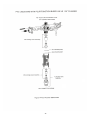
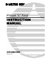
Milroyal “G” Pump
INSTRUCTION
INSTRUCTION
MANUAL
MANUAL
339-0064-000
Issued 4/1/00
THIS PAGE INTENTIONALLY BLANK
TABLE OF CONTENTS
List of Illustrations……………………………………………………………. 2
Warranty…………………………………………………………………………. 3
Section 1 Description …………………………………………….…………… 4
General …………………………………………………………….…………… 4
Principle of Operation ………………………………………………………….. 4
General Specifications …………………………………………………………. 6
Product Code (Figure 1)……………………………………………………..… 7
Section 2 Installation …………………………………………………………. 8
Unpacking ………………………………………………………….………….. 8
Safety precautions ………………………………………………….………….. 8
Storage …………………………………………………………………………… 8
Mounting …………………………………………………………………………. 9
Conversion Procedures…………………………………………………………. 9
Piping …………………………………………………………………………….. 9
Electrical Connections ………………………………………………………… 12
Section 3 Operation ………………………………………………………….. 13
Initial Start-Up …………………………………………………………………… 13
Relief Valve Adjustment…………………………………………………………. 15
Use of Air Purge Button…………………………………………………………. 16
Manual Capacity Control………………………………………………………… 17
Filling Pumping System…………………………………………………………. 17
Capacity Calibration……………………………………………………………… 17
Section 4 Maintenance ………………………………………………………. 18
Recommended Spare Parts ……………………………………………………. 18
Shipping pumps for repair …………………………………………………….. 18
Routine Preventive Maintenance ……………………………………………… 19
Corrective Maintenance ………………………………………………………. 24
Section 5 Troubleshooting Guide ………………………………………… 29
Section 6 Parts ……………………………………………………………….. 31
1
LIST OF ILLUSTRATIONS
(Located in back of manual)
Figure 2. Sample Nameplate.
Figure 3. Mounting Hole Dimensions.
Figure 4. Typical Recommended pump installation Scheme
Figure 5. Pump Drive Parts — Side View
Figure 6. Pump Drive Parts — Top View.
Figure 7. Liquid End—Top View
Figure 8. Liquid End—Cutaway View
Figure 9. MARS Valve
Figure 10. Double-Ball Check Valve Parts(1-1/4”---plastic;1-3/4,2-1/2”---PVC & metallic).
Figure 11. Plastic Single-Ball Check Valve Parts: 1-3/4, 2-1/2, & 3” Plungers
Figure 12. Plastic Check Valves for 1-1/4” Plunger
Figure 13. Metallic Check Valves for 1-1/4” Plunger
Figure 14. PVC 4 Function Bleed Valve for 1-1/4” Plunger
2
MILROYAL G METERING PUMP TWENTY-FOUR MONTH
LIMITED WARRANTY
Milton Roy Company warrants its Milroyal G metering pumps against defects in
workmanship or materials for two years under normal use from the date of shipment from
our warehouse or the warehouse of our agent. Warranties on equipment and accessories
furnished with the pump but manufactured by others are limited to the warranties offered
by the manufacturers of their respective products. This warranty is not extended to
electronic or pneumatic control devices supplied with a Milton Roy metering pump. These
items are covered by the warranties offered by the manufacturer or the Milton Roy
Warranty for Electronic Controls and Actuators.
All obligations and liabilities under this warranty are limited to refunding, repairing or
replacing (at our option), f.o.b. our plant, such reported defective units as are returned to
our plant, carrier charges prepaid. Repairs or replacements are made subject to factory
inspection of returned items.
This warranty does not extend to damage by corrosion or erosion. The materials of
construction offered are recommendations subject in all cases to verification and
acceptance by the customer. These recommendations, based on previous Company
experience and best available information, do not constitute guarantees against wear or
chemical action.
Expressly excluded from this warranty are defects caused by misuse, abuse, or improper
application, employment, or operation of the unit. Expendable items and damage
resulting from unauthorized repair are not covered by this warranty. No liability for
consequential damages or reinstallation labor is accepted. Milton Roy Company will not
assume responsibility for contingent liability for alleged failure of its products.
This warranty is in lieu of all other warranties expressed or implied.
3
SECTION 1
DESCRIPTION
GENERAL
Milroyal G pumps are reciprocating, chemical dosing pumps capable of producing
controlled flows up to 130 gallons per hour (492 L/H) at pressures up to 600 psi (41 BAR)
(depending on the model). These pumps feature the robust High Performance
Diaphragm(HPD) liquid end, which eliminates the need for contour plates, and a non-lost
motion stroke adjustment mechanism based on the variable eccentric principle. This nonlost motion design substantially reduces pressure and flow pulsations which in turn
increases the life of system components and results in a more continuous chemical
injection. It is designed for industrial service and offers an accuracy of ±1% of 100% rated
flow between 10% and 100% of its flow range.
The High Performance Diaphragm (HPD) liquid end combines all of the best
characteristics of traditional liquid ends into one technologically advanced design. Its
operating characteristics and simplicity of operation make it the best liquid end to
consider first for most metering pump applications.
Milton Roy's HPD liquid end overcomes the net positive suction head (NPSH)
restrictions associated with conventional disc diaphragm metering pumps. This is
accomplished by a unique mechanically actuated refill system(MARS) that eliminates the
need for diaphragm support plates thereby lowering pump NPSH requirements.
The MARS also does away with the need for field adjustment of the refill mechanism
by automatically compensating for process liquid modifications. This, combined with
removable check valves, makes the HPD an ideal choice for any process in which
downtime is critical.
The HPD features a preformed, PTFE faced elastomer diaphragm that is compatible
with a wide range of process liquids and chemicals. The convoluted design of this
composite diaphragm also offers extended life over conventional flat disk designs.
The HPD liquid end is particularly suitable for pumping costly, aggressive or
hazardous liquids without leakage.
PRINCIPLE OF OPERATION
Refer to Figures 5 through 10
The pump consists of two major assemblies; the drive and the liquid end. Pump
delivery is a function of the drive's stroke rate(strokes/minute), plunger size and stroke
length(%Capacity). Stroke length can be adjusted while the pump is running or stopped
by turning the stroke adjustment knob(330).
The drive motor transmits rotary motion to a worm gear speed reduction unit(343,50)
which in turn drives the variable eccentric crank(100). The adjustable crank imparts
reciprocating motion to the plunger/connecting rod assembly(60,520,525). The stroke
length is adjusted by changing the position of the variable eccentric crank in the
connecting rod assembly.
The mechanical drive system of the pump drives the plunger back and forth in the
High Performance Diaphragm (HPD) liquid end supplied with the pump. At the start of a
suction stroke, the plunger moves away from the liquid end, drawing hydraulic fluid with it.
As the hydraulic fluid is drawn back, the flexible diaphragm(510) follows, lowering the
pressure of the process fluid in the liquid end. This pressure drop causes the ball(s) in the
suction check valve (Figure 10) to be lifted up thereby allowing process fluid to pass
4
through the suction line into the diaphragm head(1020). At the same time, the pressure
drop in the diaphragm head causes the ball(s) in the discharge check valve(Fig. 10) to be
pulled closed, blocking flow back through the discharge line.
Note:
It is important that the pressure in the liquid end remain above the vapor pressure
of the process fluid during the suction stroke. If the fluid pressure drops below the
vapor pressure, cavitation will occur, negatively impacting the performance of the
pump. If you suspect the possibility of cavitation, contact your Milton Roy
Representative for assistance.
At the end of the suction stroke, the process reverses, beginning the discharge stroke.
Now the plunger moves forward, pushing hydraulic fluid before it. The hydraulic oil must
therefore press against the diaphragm, flexing it forward and raising the pressure of the
process fluid in the liquid end. This pressure increase causes the process fluid to flow
outward, forcing the discharge ball check open and the suction ball check to seat,
blocking back flow through the suction line. The process fluid flows out of the diaphragm
head and into the discharge line. This suction/discharge action is repeated with every
stroke of the pump plunger, and is the direct cause of the pumping action.
As the pump operates, a small quantity of hydraulic oil is continuously bled through the
air bleed system(970,960,980 in Fig.8) in the three-function hydraulic valve(air
bleed/relief/purge--Fig.8). An additional small quantity of hydraulic oil is also lost on every
stroke through the clearance between the plunger and displacement chamber bore. After
a while, these normal losses result in a shortage of hydraulic oil in the displacement
chamber. When this happens, the diaphragm will be pulled back tight against the back
contoured surface of the displacement chamber, and part of the diaphragm will press
against the Mechanically Actuated Refill System(MARS) valve(Fig. 9). Now, when the
plunger draws back, a vacuum is created in the displacement chamber. These two factors
(diaphragm pressing against MARS valve & vacuum in the displacement chamber) must
occur together to trigger the MARS valve.
When both of these conditions are met, the MARS valve is forced to its rearward
position, and the poppet(760) opens, allowing hydraulic oil from the reservoir to enter
through the refill valve(740 in Fig.8) and replenish the lost oil. In this manner, proper
hydraulic balance is constantly maintained in the displacement chamber.
5
GENERAL SPECIFICATIONS
Maximum Capacity Range
20 GPH(76 LPH) to 130 GPH(492 LPH)
Maximum Pressure Range
100 PSIG(7 Bar) to 600 PSIG (41 BAR)
Liquid End Design
Hydraulically Actuated Diaphragm with Mechanically Actuated Refill
System(MARS).
Drive Design
Non-Lost Motion Variable Eccentric Type.
Plunger Diameters
1-1/4”(32mm), 1-3/4”(45mm), 2-1/2”(63mm), 3”(75mm)
Liquid End Materials of Construction
PVC, 316 SS, Alloy 20,
Steady State Accuracy
±1% of 100% rated flow between 10% and 100% of rated flow
Capacity Adjustment
Micrometer(Standard): Lockable micrometer is adjustable from 0% to
100% while pump is running or stopped
Electronic(Optional): Electronic stroke length adjustment from 4-20ma
input.
Temperature Limits
Ambient Limit:
130 ºF Maximum
0 ºF Minimum
Note: Limited by standard lubricants.
Applications Engineering.
Modifications are available through
Liquid Temperature Limits:
Plastic Liquid Ends:
20oF to 140oF
o
Metallic Liquid Ends:
20 F to 190oF
Suction Pressure Limits
Minimum Internal Pressure: 3 psia(12 psi maximum vacuum)
Maximum Suction Pressure: 100 psig at 80oF and below.
Lubrication
Oil bath drive lubrication.
Paint
Two part epoxy, yellow RAL 1018
PRODUCT CODE
Milroyal G pumps are available in a variety of different configurations. The
complete product code is composed of the pump “model number” + “product
code”. For a breakdown of the options included in a specific pump, compare the
pump model number and product code found on the pump nameplate with the
model/product code breakdown shown in Figure 1. A sample nameplate is shown
in Figure 2.
6
MODEL NUMBER:
MGH--4 5
6
Digits 4 & 5: Plunger Size
Description
1-1/4”(32mm)
1-3/4”(45mm)
2-1/2”(63mm)
3”(75mm)
Digit 6: Liquid End Material
Code
20
28
40
48
Description
316 SS
Plastic(PVC)
Alloy 20
Code
1
2
5
PRODUCT CODE:
7 8
9 10
11 12
13 14
15 16
Digits 7 & 8: Stroking Speed
17 18
19 20
Digits 9 & 10: Motor
Description*Code
173 spm
10
86 spm
20
43 spm
30
*Note: SPM’s for 60 Hz, 1725 rpm motor.
Description
No motor, Flange Mount, NEMA 56C
No motor, Flange Mount, NEMA 145TC
No motor, flange mount, NEMA 182TC
No motor, Flange Mount, IEC80, F165 flange
Digits 11 & 12: Capacity Adjustment
Connection
Digits 13 & 14: Check Valve
Description
Manual, Plastic micrometer knob
Electronic(4-20 ma input)
NEMA 4, 115V
NEMA 4, 230V
Explosion Proof, 115V
Explosion Proof, 230V
Code
M2
Description
Pipe—NPT
Pipe—BSP
Pipe—DN(socket weld)
Digits 15 & 16: Base
Diaphragm
Digits 17 & 18: Rupture Detection/Double
Description
No Base(standard)
Base(optional)
Code
NN
11
E1
E2
EA
EB
Description
Single Ball
Double Ball
Code
SE
SN
SQ
Description
No Rupture Detection, Single Diaphragm(standard)
No Rupture Detection, Double Diaphragm(optional)
Rupture Detection(Gauge), Double Diaphragm(optional)
Rupture Detection(gauge + NEMA 4 pressure switch),DD (opt.)
Rupture Detection(gauge + Exp. Pr. Switch), DD (optional)
Digits 19 & 20: Check Valve Type
Code
11
22
FIGURE 1. Model/Product Code
7
Code
CB
CC
CD
MD
Code
NN
DD
C5
SN
SE
SECTION 2
INSTALLATION
UNPACKING
Pumps are shipped f.o.b. factory or representative warehouse and the title passes to
the customer when the carrier signs for receipt of the pump. In the event that damages
occur during shipment, it is the responsibility of the customer to notify the carrier
immediately and to file a damage claim.
Carefully examine the shipping crate upon receipt from the carrier to be sure there is
no obvious damage to the contents. Open the crate carefully so accessory items fastened
to the inside of the crate will not be damaged or lost. Examine all material inside the crate
and check against packing list to be sure that all items are accounted for and intact.
SAFETY PRECAUTIONS
When installing, operating, and maintaining the Milroyal G pump, keep safety
considerations foremost. Use proper tools, protective clothing, and eye protection when
working on the equipment and install the equipment with a view toward ensuring safe
operation. Follow the instructions in this manual and take additional safety measures
appropriate to the liquid being pumped. Be extremely careful in the presence of
hazardous substances (e.g., corrosives, toxins, solvents, acids, caustics, flammables,
etc.).
STORAGE
Temporary Storage (Less than 6 Months)
It is preferable to store the material under a shelter in its original package to
protect it from adverse weather conditions. In condensing atmospheres, follow the
long term storage procedure.
Long Term Storage (Longer than 6 Months) Primary Considerations
The primary consideration in storage of pump equipment is to prevent corrosion
of external and internal components. This corrosion is caused by natural circulation
of air as temperature of the surroundings change from day to night, day to day,
and from season to season. It is not practical to prevent this circulation which
carries water vapor and other corrosive gasses, so it is necessary to protect
internal and external surfaces from their effects to the extent possible.
When the instructions given in this section are completed, the equipment is to
be stored sheltered/protected from direct exposure to weather. The prepared
equipment should be covered with a plastic sheet or a tarpaulin, but in a manner
which will allow air circulation and prevent capture of moisture. Equipment should
be stored 12 inches or more above the ground.
If equipment is to be shipped directly from Milton Roy into long term storage,
contact Milton Roy to arrange for factory preparation.
Pump Drive
1. Flood the pump drive housing with a high grade lubricating oil/rust preventative
such as Mobile Oil Corporation product "Mobilarma 524." Fill the housing
completely to minimize air space and water vapor condensation. After storage,
8
drain this material and refill the equipment to the correct oil level with the
recommended lubricant for equipment commissioning.
2. Remove drive motor and brush all unpainted metal surfaces with multipurpose
grease (NLGI grade 2 or 3). Store motor unattached.
Electrical Equipment
1. Motors should be prepared in the manner prescribed by their manufacturer. If
information is not available, dismount and store motors as indicated in step 3
below.
2. Dismount electrical equipment (including motors) from the pump.
3. For all electrical equipment, place packets of Vapor Phase Corrosion Inhibitor
(VPCI) inside of the enclosure, then place the entire enclosure, with additional
packets, inside a plastic bag. Seal the bag tightly closed. Contact Milton Roy
Service Department for recommended VPCI materials.
MOUNTING
Support the pump firmly in a level position on a solid, vibration-free foundation,
preferably with the base above floor level to protect the pump from wash downs and to
provide easier access for service. Be sure to allow enough space around the pump for
easy access during maintenance operations, pump adjustments, and/or oil filling or
draining procedures.
Milroyal G pumps are provided with mounting holes to accommodate anchor bolts.
Refer to Figure 3 for mounting hole dimensions.
Some Milroyal G pumps are shipped with motors dismounted. After anchoring pump in
position, install motor, referring to Figure 5. To avoid damage to pump drive during
operation, make sure spring (360) provided with pump is installed in worm shaft
prior to motor installation. Pumps installed outdoors should be protected by a shelter.
CONVERSION PROCEDURES
A Milroyal G pump can, in some cases, be converted from one liquid end plunger size
or material of construction to another. For more information on converting between
different liquid end models, please contact the Milton Roy factory or your local authorized
representative.
PIPING CONNECTIONS
NPSH Considerations
The Milroyal G HPD liquid end is far superior to conventional diaphragm liquid ends for
suction lift and many other NPSH-critical applications. In these demanding applications,
the patented diaphragm and refill mechanism give this liquid end truly exceptional
performance.
For more NPSH information, refer to the Practical Handbook for NPSH, bulletin 220,
but apply a 3 psia limitation(instead of 9 psia) in evaluating applications for this liquid end.
Size piping to accommodate peak instantaneous flow. Because of the reciprocating
motion of the pump diaphragm, pump delivery follows an approximate sine curve with a
peak instantaneous flow equal to pi(3.14) times the average flow. Therefore, piping must
be designed for a flow 3.14 times the pump capacity; this means that a pump rated for
9
100 gallons per hour (379 L/hr.) requires piping sufficient for 3.14 x 100 gph, or 314 gph
(1188 L/hr.).
To minimize viscous flow losses when handling viscous liquids, it may be necessary to
use suction piping up to four times larger than the size of the suction connection on the
pump. If in doubt, contact your nearest Milton Roy representative to determine the
necessary pipe size.
General Piping Considerations
• Use extreme care in piping to plastic liquid end pumps with rigid pipe such as PVC. If
excessive stresses or vibration is unavoidable, flexible connections are
recommended.
• Use piping materials that will resist corrosion by the liquid being pumped. Use care in
selecting materials to avoid galvanic corrosion at pump liquid end connections.
• Use piping heavy enough to withstand maximum pressures.
• Remove burrs, sharp edges, and debris from inside piping. Blow out all pipelines
before making final connections to pump.
• Because vapor in the liquid end will cause inaccurate pump delivery, piping should be
sloped down to pump suction check valve to prevent vapor pockets
• When pumping suspended solids (such as slurries), install plugged crosses at all 90°
line turns to permit line cleaning without dismantling piping.
• See Figure 4 for a typical recommended pump installation scheme.
Suction Piping Considerations
• It is preferable to have the suction of the pump flooded by locating the liquid end
below the lowest level of the liquid in the supply tank. Installing the supply vessel on
the suction line in close proximity to the pump will help ensure a flooded suction line.
• Avoid negative suction pressure conditions (suction lift), as such conditions adversely
affect metering accuracy. A lift of 20 Ft. of water column is the maximum suction lift
permissible.
• Milroyal G pumps are intended to be operated with process liquid supplied at or above
atmospheric pressure. Although these pumps can move liquids supplied at less than
atmospheric pressure, in these negative pressure applications it is important that all
connections be absolutely drip free and vacuum tight.
• When pumping a liquid near its boiling point, provide enough suction head to prevent
the liquid from "flashing" into vapor when it enters the pump liquid end on the suction
stroke.
• If possible use metal or plastic tubing for the suction line because such tubing has a
smooth inner surface and can be formed into long, sweeping bends to minimize
frictional flow losses.
• A strainer should be used in the suction line to prevent foreign particles from entering
the liquid end. This and any other measures to prevent debris from entering and
fouling the ball-checks will give increased maintenance-free service. Check strainer
frequently to prevent blockage which could lead to cavitation.
• Keep suction piping as short and straight as possible.
• Piping size should be larger than the liquid end suction fitting to prevent pump
starvation.
• If long suction lines are unavoidable, install a stand pipe near the pump in the suction
line.
10
•
Suction piping must be absolutely airtight to ensure accurate pumping. After
installation, test suction piping for leaks with air and soap solution.
Discharge Piping Considerations
• Install pipe large enough to prevent excessive pressure losses on the discharge
stroke of the pump. Maximum pressure at the discharge fitting on the liquid end must
be kept at or below the rated pressure (Max. allowable working pressure shown on the
pump nameplate).
• The pump will not deliver a controlled flow unless the discharge line pressure is 10 psi
greater than the suction line pressure. There are a number of ways to create an
artificial pressure, such as by installing a back pressure valve. (Please contact Milton
Roy for recommendations to increase back pressure in slurry applications.)
• When pumping water-treatment chemicals directly into boiler drums, use one liquid
end assembly for each boiler drum. Discharging into a manifold having the slightest
pressure difference between its several discharge connections can diminish metering
accuracy as the outlet with the lowest pressure will receive more liquid than the outer
outlets.
Back Pressure Valves
A Milton Roy Back Pressure Valve should be installed in the discharge line near the
pump to ensure sufficient discharge head pressure for proper pump metering action.
Normally, the valve should be located near the pump. However, back pressure valves for
large pumps with long and extremely small discharge lines may have to be installed near
the point of discharge into the process (to minimize siphoning tendencies).
Pulsation Dampeners
An accumulator, surge chamber, surge suppressor, or pulsation dampener should be
used with the back pressure valve in the discharge line to absorb the flow peaks between
the pump and the back pressure valve. Without the pulsation dampener the valve
mechanism will snap open and closed with the surge from each pump stroke. The
pulsation dampener will allow the back pressure valve to oscillate about a partly-closed
position, thus minimizing wear on the valve. Discharge line pulsation dampeners offer the
further advantage of limiting the flow and pressure variations characteristic of this kind of
pump. Installing a properly sized pulsation dampener will improve pump performance and
may reduce system costs dramatically by permitting the substitution of smaller piping.
Please contact Milton Roy Company for further information on pulsation dampeners.
Safety Valves
Maximum safety and reliability may be ensured by protecting liquid ends and piping
with an external relief valve installed in the system discharge line. Although the pump is
protected against excessive pressure by an internal relief valve, to prevent a blocked
discharge line from causing damage to the piping or process equipment, install a Milton
Roy Safety Valve in the pump discharge line. This valve is designed and sized to handle
system flow rates and pressures safely while resisting corrosion by the process liquid.
Install the safety valve in the discharge line between the pump and the nearest shut-off
valve. (This will prevent potential system damage from accidental valve closure.) Pipe the
safety valve outlet back to the suction tank or to drain, but in either case ensure that the
pipe end is continuously visible so safety valve leakage may be detected. Milton Roy
11
safety valves must be installed at top of supply tank in order to function properly (see
Figure 4).
Check Valves
A check valve should be installed at the point where the discharge line enters a boiler
or other high-pressure vessel. This will prevent back flow through the discharge piping
and will isolate the pump discharge from system pressures (a safety consideration).
Shut-off Valves
In order to isolate the pump during maintenance, provide shut-off valves in both
suction and discharge lines next to the pump. Locate discharge line shut-off valve
downstream from the inlet connection of the safety valve. Figure 4 shows recommended
valve locations.
ELECTRICAL CONNECTIONS
Ensure that the electrical supply matches the pump motor nameplate characteristics.
Before operating the pump, check the direction of rotation of the motor to be sure it
matches the direction of the arrow stamped on the motor (rotation should be clockwise
when viewed from the top of the motor). If motor rotation is incorrect, refer to the motor
data plate or motor manufacturer's instructions for reversing.
Caution:
Operation with the wrong motor rotation will damage the pump and motor and void
the warranty.
Caution:
Do not forget to connect the pump to an earth ground!
Electric protection of the motor (fuses, overload meters or relays) should correspond to
the rated current indicated on the motor data plate.
12
SECTION 3
OPERATION
INITIAL START-UP
Check that all mounting bolts are tight, piping is installed properly, and the discharge line
is open. Check oil drain plug for tightness. Remove the orange oil fill cap and fill the pump
casing until level is between the top two marks on the oilcap dipstick.(approximately 3-1/2
quarts ). DO NOT OVERFILL ABOVE TOP DASH!
NOTE:
The oil furnished with the pump is grade AGMA No. 5 EP with a viscosity of 1000
SSU at 100°F (218.4 cSt at 40°C). For operation in ambient temperatures below
50°F (10°C), substitute AGMA No. 2 EP with a viscosity of 400 SSU at 100°F (86.4
cSt at 40°C). Manufacturers' equivalent oils are shown below.
CAUTION: Do not start up pump drive motor before filling gear box with oil or
serious damage will occur.
ABOVE 50°F:
Chevron N.L. Gear Compound 220
Exxon Spartan E.P. 220
Mobil Mobilgear 630
Texaco Meropa 220
Shell Omaha 220
BELOW 50°F:
Chevron N.L. Gear Compound 68
Exxon Spartan E.P. 68
Mobil Mobilgear 626
Texaco Meropa 68
Shell Omaha 68
Start-Up for New Pump
For pumps received from the factory, the displacement chamber(600) is already filled with
oil. Simply remove the orange oil fill cap from the pump casing and fill the casing with
the specified oil to a level between the top two dashes on the dipstick. DO NOT
OVERFILL ABOVE TOP DASH! Pump is now ready for operation. Operation of the air
purge button may be required to remove air that may have come out of solution from the
oil during shipment and storage. Refer to “USE OF AIR PURGE BUTTON” section for
operation instructions. The integral pump relief valve is factory adjusted according to
customer specified setting.
For instructions on adjustment of the pump relief valve
please refer to the next section.
CAUTION:
Before switching on power to the pump, turn the capacity adjustment knob to zero.
Check that all shut-off valves in the suction and discharge lines are open before
increasing the capacity adjustment from zero.
13
Start-Up of Pump Containing No Oil in Casing and Displacement Chamber
The following instructions assume that both the pump casing and liquid end(displacement
chamber) contain no oil. This condition typically exists when the pump is subjected to
annual maintenance during which oil may be drained from the pump casing and oil may
escape from the displacement chamber during diaphragm replacement. New pumps
received from the factory will have an empty pump casing and a filled displacement
chamber(liquid end). Please refer to the previous section for start-up of new pumps. After
pump casing is filled to correct oil level(between top two dashes on oil cap dipstick),
perform the following operations before placing the pump into service. Numbers refer to
item numbers shown in assembly drawings(Figures 7--9) located in the back of this
manual.
1. Remove hydraulic 3-function valve(refer to Figure 8):
a. Remove relief valve cap piece(850).
b. Make sure relief valve locknut(900) is tight to maintain previous relief valve setting
upon start-up.
c. Remove purge button and relief valve adjustment assembly by removing large
adjustment nut(910).
d. Using needle-nose pliers, remove spring(950).
e. Using same pliers, remove relief valve poppet by gently gripping the top of the
valve body(960).
2. Make sure pump capacity adjustment is set to 100%.
3. Fill the opening in the displacement chamber(600) through the port uncovered by
removal of the 3-function valve in step 1 with the same oil used to fill the pump casing.
Fill the chamber slowly, allowing air bubbles to escape, until the oil level reaches the
level of the drain tube(640).
4. Reinstall 3-function valve:
a. Gently gripping the top of the relief valve poppet(960) with needle-nose pliers, drop
the poppet assembly down into the empty relief valve port.
b. Drop spring(950) back into relief valve port.
c. Make sure washer(935) is in place above the o-ring(940) on purge stem(930) and
reinstall purge and relief valve adjustment assembly by screwing large adjustment
nut(910) back into place. Make sure adjustment nut(910) is tight.
d. Reinstall relief valve cap piece(850).
5. The pump is now properly filled with oil and ready for service. If the relief valve
locking nut(900) remained tight during the above procedure, the relief valve setting
should remain unchanged. If not, refer to next section for instructions on how to set
relief valve.
CAUTION:
Before switching on power to the pump, turn the capacity adjustment knob to zero.
Check that all shut-off valves in the suction and discharge lines are open before
increasing the capacity adjustment from zero.
6. Make sure that all air has been bled from the suction piping and pump head. This
can be accomplished by opening all suction line valves as well as the system drain
(Prime/Air Purge) valve shown in Figure 4 and allowing fluid to flow into drain until all
air has been purged. If drain valve not present, with the pump capacity set to 100%,
operate the pump under no discharge pressure until the entire pumping system has
been filled.
14
RELIEF VALVE ADJUSTMENT
All Milroyal G liquid ends have a built in relief valve which allows hydraulic fluid to
return to the pump casing if excessive pressure builds up in the discharge line. This
effectively stops the pump from pumping, since the forward stroke of the piston will not
displace the hydraulic fluid and force the diaphragm to flex.
During operation of the
pump, a relief condition caused by overpressurization can easily be seen by looking
through the sight glass(630, Fig.7) for excessive oil flow from the drain tube(640, Fig.8).
NOTE:
Under normal operation, a few drops of oil should escape from the drain tube
during each pump stroke due to normal oil flow through the airbleed ball(970,fig.8).
If a stream of oil from the drain tube is evident on each pump stroke, the system
pressure has exceeded the pump relief valve setting and the pump is in a relief
condition.
The Milroyal G liquid end relief valve may be adjusted to operating conditions by the
following procedure. Adjust the relief valve after first installing the pump and after any
maintenance procedures.
Warning!
The pressure relief valve is factory set to open at a pressure 15% over the
customer specified operating pressure or at 15% above the maximum pressure
rating of the pump if no operating pressure is specified by the customer. When
adjusting the valve setting, never set the valve at a pressure greater than 15%
over the pump maximum pressure rating.
Relief Valve Adjustment(With an Adjustable System Backpressure Valve).
Refer to Figures 7 & 8.
The following procedure assumes that a backpressure valve and pressure gauge are
installed in the discharge line.
If these components are not installed, refer to next
section.
1. Make sure all system shut off valves are open and that the backpressure valve is
backed out to allow for flow against zero discharge pressure.
2. Start pump and set capacity at 100%. If a drain valve is present in the discharge line,
pump process liquid to drain or other safe point to establish proper pumping action.
Close drain.
3. Slowly increase system pressure until:
(a)significant flow is observed from the drain tube(640, fig.8) as viewed through the
sight glass(630,fig. 7)
or
(b)the system pressure reaches 15% over the desired system pressure.
4. For condition (a) in step 4, if relief condition occurs at less than 15% above desired
pump operating pressure, the relief valve setting must be increased. Remove valve
cover(850) and increase relief valve setting by turning the adjustment screw(890)
clockwise until only a few drops of oil escape on each pump stroke(normal leakage
past airbleed ball--980). Increase system pressure to 15% above desired operating
pressure to verify that pump is now in relief condition. If it is not, reduce relief valve
setting by turning adjustment screw(890) counterclockwise until relief is observed in
sight glass drain tube at a pressure equal to 15% greater than desired operating
pressure. Lock-in relief valve setting by tightening locking nut(900) while holding
15
adjustment screw(890) stationary.
The relief valve is now properly adjusted.
Reinstall valve cover(850).
5. For condition (b) in step 4, the setting of the relief valve should be reduced. Remove
valve cover(850) and turn adjustment screw(890) counterclockwise until relief is
observed in sight glass drain tube at a pressure equal to 15% greater than desired
operating pressure. Lock-in relief valve setting by tightening locking nut(900) while
holding adjustment screw(890) stationary. The relief valve is now properly adjusted.
Reinstall valve cover(850).
Relief Valve Adjustment(Without an Adjustable System Backpressure Valve).
If no adjustable backpressure valve is present in the discharge line, use the following
simplified procedure to check and/or set the relief valve setting.
1. If pump is in a relief condition at normal operating pressure, the relief valve setting
should be increased. Remove valve cover(850) and increase relief valve setting by
turning the adjustment screw(890) clockwise until only a few drops of oil escape on
each pump stroke(normal leakage past airbleed ball--970). Turn adjustment screw
an additional ½ turn to provide an adequate buffer zone. Lock-in relief valve setting by
tightening locking nut(900) while holding adjustment screw(890) stationary.
The
relief valve is now properly adjusted. Reinstall valve cover(850).
2. If pump is not in a relief condition at normal operating pressure, and the operator
wishes to reset the valve setting to approximately 15% above operating
pressure(recommended), use the following procedure. Remove valve cover(850) and
decrease the
relief valve setting by turning the adjustment screw(890)
counterclockwise until a stream of oil flows from the drain tube(640) on each pump
stroke. Now slowly turn adjustment screw clockwise until until only a few drops of oil
escape on each pump stroke(normal leakage past airbleed ball).
Turn screw an
additional ½ turn to provide an adequate buffer zone. Lock-in relief valve setting by
tightening locking nut(900) while holding adjustment screw(890) stationary.
The
relief valve is now properly adjusted. Reinstall valve cover(850).
USE OF AIR PURGE BUTTON
Refer to Figures 7 & 8:
As with any hydraulically actuated diaphragm pump, dissolved air will come out of
solution during normal operation which can negatively impact pump performance if not
removed from the pump displacement chamber. The Milroyal G hydraulic 3-function
valve is equipped with two mechanisms for removal of this gas: a continuous airbleed and
an air purge button. The continuous airbleed portion of the valve is composed of a sealed
ball(970) which allows for a controlled leakage of a few drops of oil, and any small
accumulations of evolved gas, on each pump stroke. Larger quantities of air can be
quickly removed by pressing the spring-loaded purge button(860), until it reaches its
mechanical stop, for a few seconds. Upon doing so, the operator will observe a stream
of oil and air escaping from the drain tube(640). The need for use of the purge button to
remove a large quantity of air can be caused by several factors:
1. Blocked suction line: A partially or fully blocked suction line can create a
vacuum pressure condition in the hydraulic system which pulls significant
quantities of dissolved gas from solution.
2. Oil Change: The recommended annual changing of the oil in the pump drive
can lead to the presence of air pockets in the displacement chamber(600).
16
3. Diaphragm Replacement: Results in significant loss of oil from the
displacement chamber.
4. Pump Start-up After Long Idle Period: If the pump has sat idle for a significant
time, gas may come out of solution from the oil and collect into pockets which
can negatively impact pump flow. Depression of the purge button will quickly
evacuate these pockets and restore the pump to desired performance.
The operator should only activate the purge button if some type of pump upset occurs
such as the above 4 examples. When activating the purge, only press button for 2-3
seconds or until a stream of oil flowing from the drain tube(640) is seen through the sight
glass(630). Immediately after activation of the purge button, a temporary reduction in
flow will occur as the refill system replenishes oil lost during the purge. However, the
pump should return to normal operation within 1 to 2 minutes after activation of the purge
button. If after that time, the pump flow rate is still less than it should be, repeat the
purge operation and wait another 2 minutes. If flow has still not resumed to expected
levels, consult the troubleshooting section of this manual.
MANUAL CAPACITY CONTROL
To adjust pump capacity on standard pumps equipped with manual stroke adjustment,
first loosen the stroke locking screw located in the pump side cover. Pump capacity is
then adjusted by turning the micrometer-type stroke adjustment knob clockwise to
decrease capacity or counterclockwise to increase capacity as required. The adjustment
scale is marked in percent (%) of full stroke, with calibration lines on the knob at 1%
intervals. After adjusting the knob to the desired capacity setting, hand tighten the stroke
locking screw to maintain the capacity setting.
FILLING PUMPING SYSTEM
For proper pump operation, it is especially important that pump suction and discharge
lines be free of entrained air. To ensure this condition, operate the pump without any
discharge pressure and fill the entire pumping system with liquid before starting pressure
tests. A simple method to assure priming of the pump is to install a tee and a shut-off
valve at the discharge connection of the pump.
If the pump is idle for long periods, temperature changes in the process liquid may
produce air in the system. To discharge the air, install a valve in the discharge line which
will allow the process liquid to be pumped to a drain when starting the pump.
CAPACITY CALIBRATION
After the first 12 hours of operation, the pump should be tested and calibrated to find
the exact pump capacity under specific operating conditions and capacity settings for the
specific fluid being pumped. Typically, calibrating the pump at 100, 50, and 10 percent
capacity settings is enough to establish a pump performance curve throughout the
adjustment range.
The pump can be calibrated by measuring the decrease in liquid level pumped from a
calibrated vessel. This method is recommended for hazardous liquids because it
eliminates operator contact with the liquid. Milton Roy test-tube Calibration Columns are
available for convenient and accurate calibration of any pump. The pump can also be
calibrated by collecting and measuring pumped liquid at the pump discharge port in which
case it will be necessary to create discharge head at the liquid takeoff point so that the
pump will operate properly. (See Section 2 for recommended ways to do this.)
17
CAUTION: This method is not generally recommended as it may expose
operating personnel to hazardous liquids.
SECTION 4
MAINTENANCE
RECOMMENDED SPARE PARTS
To avoid delays in repairs, a Routine Preventative Maintenance Kit should be ordered
for each pump. The RPM kit contains an oil strainer and check valve parts. Part orders
must include the following information:
1. Quantity required.
2. Part Number
3. Part Description
4. Pump serial number(found on pump nameplate).
5. Pump model number(found on pump nameplate).
6. Pump product code(found on pump nameplate).
Always include the serial number, model number, and product code in all correspondence
regarding this unit.
SHIPPING PUMPS FOR REPAIR
Pumps can not be accepted for repair without a Return Material Authorization.
Pumps should be clearly labeled to indicate the liquid being pumped. Process liquid
should be flushed from the pump liquid end and oil should be drained from the pump
housing and displacement chamber. To drain oil from the displacement chamber,
unscrew the refill valve body(660, fig. 8) from the displacement chamber. Allow oil to
drain into a waste container. Remove diaphragm(510) and tilt up the back of the pump
until oil ceases to drain from the front of the pump.
NOTE:
Federal law prohibits handling of equipment that is not accompanied by an OSHA
Material Safety Data Sheet (MSDS). A completed MSDS must be packed in the
shipping crate with any pump shipped for repair. These safety precautions will aid
the troubleshooting and repair procedure and preclude serious injury to repair
personnel from hazardous residue in pump liquid end. A Materials Safety Data
Sheet must accompany all returns.
All inquiries or parts orders should be addressed to your local Milton Roy representative
or distributor. Alternatively, inquiries and/or parts orders may be sent to:
Milton Roy Company
Flow Control Division
201 Ivyland Road
Ivyland, PA USA 18974-0577
Attn: Aftermarket Department
18
ROUTINE PREVENTATIVE MAINTENANCE
Warning!
Before any maintenance, relieve all pressure from system, isolate liquid end from
all sources of process liquid with appropriate valving, and purge liquid end of all
process liquid.
Oil Replacement
Initially, change oil in pump casing after the first 250 hours of operation. Then
change oil after every 4000 hours of operation or every six months whichever
comes first. Oil can be drained by removing the drain plug(20, fig. 6). When oil
has finished draining, make sure that the area around the drain hole is clean.
Screw drain plug back in securely. Fill the pump housing with the recommended
oil until the level is between the top two marks on the dipstick.
DO NOT
OVERFILL(above top mark)! Replace the oil fill cap and screw firmly in place.
Dispose of oil according to any federal, state or local codes which may apply.
Note:
It is not necessary to purge the liquid end displacement chamber of oil
during annual oil replacement.
Check Valves
Milton Roy company recommends that check valve balls, seats, gaskets, and orings be replaced on an annual basis. If highly corrosive material (acids, slurries,
etc.) is being pumped, some applications may require more frequent replacement.
Milton Roy recommends an annual tune up using a Routine Preventive
Maintenance (RPM) Kit. RPM kits contain replacements for those parts which are
subject to wear; specifically the ball checks, check valve seats, gaskets/seals, and
the strainer. Replacing these parts annually with an RPM kit can reduce the
possibility of unexpected downtime and will help to extend pump life.
To determine if check valves need maintenance, disassemble the check valves
following the instructions in the following "Check Valve Replacement” section. In
valves that permit disassembly, inspect the ball check and seat for chemical or
physical damage. The ball should be perfectly round and free of pits, mars, or
scratches. The seat should retain a smooth edge where the ball contacts for
proper sealing.
If the seat edge is worn or damaged, or has any pits, mars, or
scratches, it should be replaced. If the ball and/or seat is excessively damaged,
the replacement schedule should be shortened accordingly. If the ball and seat are
both in good condition, the replacement schedule can be lengthened.
Caution:
Before carrying out any servicing operation on the metering unit or pipes,
disconnect electrical power from the pump, and take the necessary steps to
ensure that the harmful liquid they contain cannot escape or come into contact with
personnel. Suitable protective equipment must be provided. Check that there is no
system fluid pressure before proceeding with dismantling of liquid end
components.
19
Cleaning Fouled Check Valves
Check valve assemblies are designed to be self cleaning and should seldom
need servicing. Fouled check valves can usually be cleaned by pumping a solution
of mild detergent and warm water (if compatible with liquid being pumped) for 15
minutes, followed by flushing with water.
Check Valve Replacement
Before beginning work on the valve assemblies, make sure the shut-off valves
are closed and that pressure has been bled from the system. When replacing the
valves, take care to systematically change their O-rings and/or gaskets. Take care
to properly assemble the valve assemblies. In valves that permit replacement of
ball and seat, the ball must be placed on the sharp edge of the seats.
For each plunger size, check valves are supplied in three different
configurations: plastic-single ball, plastic-double ball, and metallic-double ball. Be
sure to refer to the appropriate instructional set below pertaining to your plunger
size and valve type.
Caution:
Be sure to follow instructions carefully and refer to the appropriate figure
when reassembling check valves. If check valve cartridges are installed
incorrectly, one of the following will occur: (a) immediate severe damage to
pump mechanism, (b) no pumping, (c) reverse pumping action (from
discharge line into suction line).
1-1/4” Plunger;Plastic Single Ball Check Valves: see Figure 12
1. Unscrew the valve body [445].
2. Remove the cartridge assembly(425): includes cartridge(ball, seat, ball
guide), o-ring, and washer.
3. Clean the valve housing and mating port in the liquid end.
4. Press a new clear plastic washer into valve body.
5. Install new cartridge valve assembly in orientation shown in figure 12.
• Make sure that seat end of cartridge(white) is always facing down.
• On discharge side, drop cartridge assembly into threaded port in
head. The o-ring should be stretched around outside of cartridge
on same end as ball seat. Screw valve body into discharge side of
diaphragm head until valve is hand tight. Do not overtighten.
• On suction side, drop cartridge assembly into check valve body. The
o-ring should be stretched around outside of cartridge on opposite
end of ball seat. Screw suction valve housing with cartridge valve
into suction side of head. Do not overtighten.
1-1/4” Plunger; Metallic Double Ball Check Valves: see Figure 13
The metallic check valves used on the 1-1/4” plunger size pumps are
precision assembled at the factory. Do not attempt to disassemble
these cartridges. If they become inoperative, flush them with
solvent, wash them with warm detergent and blow them out with
compressed air to remove any foreign matter. If this treatment does
not eliminate the trouble, the cartridge assembly should be replaced.
A. Disassembly(refer to fig. 13)
20
1. The check valve cartridge assemblies use an SAE straight thread
with an O-ring seal to facilitate port alignment with the connecting
pipes. To remove the cartridge from the liquid end, first loosen
the lock nut(435) one or two threads, then unscrew the
cartridge(444,445).
2. Remove and discard the o-ring(441) and split ring(439).
3. Carefully clean any parts to be reused. If any chemicals are used
in the cleaning process, ensure that they are compatible with the
process liquid.
B. Reassembly(refer to fig. 13)
1. To install the cartridge, position the lock nut(435) toward the
shoulder of the cartridge so that the recess on the face of the lock
nut is adjacent to the O-ring(441).
2. Make certain the split ring(439) is coiled in a counterclockwise
helix(this is opposite the direction normally employed by suppliers
of these rings). Fit this split ring in the lock nut recess. Push it
firmly down in the recess as completely as possible.
3. Install a new O-ring(435) against the split ring.
Note: To assure a tight, leak free seal, new o-rings and
split rings should be used each time the check valves are
disassembled.
4. Screw the cartridge assembly(444,445) into the liquid end until
the O-ring band is approximately level with the top of the spotface
in the liquid end, then screw it one(1) additional turn plus a partial
turn as required to align the pipe thread port with connecting pipe.
Caution!!
Suction and discharge check valve cartridges are not
identical. Be sure that the correct cartridge is being
screwed into the proper port. (Discharge cartridges have
hexagonal cap on the top; suction cartridges do not.) If
check valve cartridges are installed into the wrong port,
one of the following will occur: (a)immediate severe
damage to pump mechanism, (b)no pumping, (c) reverse
pumping action(fron discharge line into suction line).
5. After completing pipe connection, tighten lock nut securely
against spotface so that O-ring is trapped in chamfer of liquid end
thread. Make sure that the split ring is completely contained in
its recess and not extending to the outside.
1-3/4, 2-1/2, and 3”Plungers: Plastic Single-Ball Check Valves: see Figure
11
A. Disassembly
1. Unscrew the union nut (435). The union end (445) is held in place by the
union nut and will now separate easily from check valve ball guide(424).
2. Unscrew the ball guide (424) from the liquid end.
21
3. Screw the union nut partially(one or two turns) onto the end of the ball
guide containing the seat. Be sure the union nut is loosely installed to
allow for a gap for the seat (420) to drop into as it is removed from the
ball guide.
4. Sit the ball guide/union nut onto a flat surface with the union nut down.
Looking into the top of the ball guide, you will see four large holes
surrounding one small hole. Insert a thin, blunt instrument such as a hex
head screwdriver into the small center hole until it rests on the top of the
ball (422).
5. Tap screwdriver gently with a hammer until ball and seat are released
from the ball guide.
Caution:
If you are disassembling unit for inspection only, be sure to use
a blunt instrument and tap gently to avoid damaging the ball. If
the ball and/or seat are damaged during disassembly, they will
need to be replaced. To avoid damage, if available, it is
advisable to use gentle air pressure (applied at end opposite the
seat - 420) for ball and seat removal.
6. Carefully remove the two o-rings(419) from the ball guide and seat.
7. Inspect the balls carefully. If they are smooth, round and free of deposits
or pits, they are suitable for continued use. Examine the check valve
seats. The area of the seat in contact with the ball (the un-chamfered
side) must be in near perfect condition for continued use. Any visible
imperfection on the seating surface (pits, erosion, cracks) necessitates
replacement of the seat. If both the balls and the seats are in good
condition, then the length of time between parts replacement may be
increased. If the balls and seats are severely damaged, then the length
of time between parts replacement should be shortened. Carefully clean
any parts to be reused. If any chemicals are used in the cleaning
process, ensure that they are compatible with the process liquid.
B. Reassembly
1. Drop the ball into the curved inner chamber end of the ball guide.
2. Sit the ball guide on a flat surface so that the side with the ball faces
upwards. Position seat on the ball guide, trapping the ball inside. When
the seat is pressed into the ball guide, the beveled edge of the seat must
be facing outward. The bevel should not face the inside of the check
valve (refer to Figure 11). Use a flat surface such as a board to press the
seat into the ball guide with firm, even pressure.
Caution:
If the seat is improperly positioned(with ball against beveled
surface), the ball will not create a tight seal and poor pumping
performance will result.
3. Fit new o-rings into grooves in the ball guide and seat.
Note:
To assure a tight, leak free seal, new o-rings should be used each
time the check valves are disassembled.
4. Position the union end(445) onto the correct end of the ball guide. Refer
to Figure 11 as the correct end is determined by whether the valve is
22
intended for the suction or discharge port of the liquid end. Slip the
union nut(435) over the union end and screw tightly(hand tight only) onto
the ball guide.
Caution:
The order of assembly of the suction and discharge check
valves is different. Refer to Figure 11 for proper assembly order.
If check valve cartridges are installed incorrectly, one of the
following will occur: (a) immediate severe damage to pump
mechanism, (b) no pumping, (c) reverse pumping action (from
discharge line into suction line).
5. Screw the valve assembly into the liquid end body(hand tight only). DO
NOT OVERTIGHTEN!
1-1/4”Plunger, Plastic Double Ball Check Valves
1-3/4”, 2-1/2”, 3” Plungers, Plastic & Metallic Double Ball Check Valves
A. Disassembly(Refer to Figure 10).
Double ball check valves differ from the plastic single ball check in that the
ball seat is now integral to the ball guide. The seats cannot easily be
inspected for damage or wear. If you suspect that the check valve may be
damaged or worn, replace the entire check valve assembly as per
instructions below.
1. If metallic valve, unscrew the coupling(445) from the ball
guide(424). If plastic, unscrew the union nut(435,fig.11) and
remove union end(445,fig.11) from the ball guide(424).
2. Unscrew the ball guide (424) from the liquid end.
3. Remove and discard the o-rings (419).
4. Remove ball stop(420) and balls(421,422). Inspect the balls
carefully. If they are smooth, round and free of deposits or pits,
they are suitable for continued use. Examine the ball seat areas
in the valve body(424). A magnifying glass is recommended for
this inspection. The seat must be in near perfect condition for
continued use. Any visible imperfection on the seating surface
(pits, erosion, cracks) renders the seat unusable thereby requiring
replacement of the valve body(424). If both the balls and the
seats are in good condition, then the length of time between parts
replacement may be increased. If the balls and seats are severely
damaged, then the length of time between parts replacement
should be shortened. Carefully clean any parts to be reused. If
any chemicals are used in the cleaning process, ensure that they
are compatible with the process liquid.
B. Reassembly(Refer to Figure 10):
1. Drop the balls(422, 421) into the valve body(424). Drop ball
stop(420) into place making sure that side with o-ring groove is
facing up. Install new o-rings(419) on both ends of valve body.
Note:
To assure a tight, leak free seal, new o-rings should be used
each time the check valves are disassembled.
23
2. Screw the correct end of the check valve assembly into the liquid
end(hand tight only) trapping a new o-ring between the liquid end
and the check valve assembly. DO NOT OVERTIGHTEN!
Caution!!
The end of the check valve that is screwed into the pump
head is different for the suction and discharge check
valves. Refer to Figure 10 for proper assembly order. If
check valve cartridges are installed incorrectly, one of the
following will occur: (a) immediate severe damage to
pump mechanism, (b) no pumping, (c) reverse pumping
action (from discharge line into suction line).
3. If metallic check valve, screw the coupling(445) onto the check
valve assembly, trapping a new o-ring (419) between the coupling
and the check valve assembly. If plastic check valve, position the
union end(445) onto the correct end of the ball guide. Slip the
union nut(435) over the union end and screw tightly(hand tight
only) onto the ball guide. DO NOT OVERTIGHTEN!
Oil Strainer Replacement
Refer to Figure 8.
Over time, the oil strainer(670) which screws into the refill valve
body(660) can become fouled or clogged. It should therefore be replaced
yearly and is included with the check valve parts in the RPM Kit. If the
strainer becomes clogged more frequently than once a year (which is
extremely unlikely), it can be ordered separately.
Since the oil must first be drained from the pump casing, it is a good idea
to schedule strainer replacement with oil replacement.
1. Drain oil as described in the above “Oil Replacement” section of this
manual.
2. Unscrew the strainer(670) from the refill valve body(660).
3. Clean any debris from the strainer cavity in the valve body.
4. Screw a new strainer into the refill valve body.
5. Refill pump casing with recommended oil as described in the “Oil
Replacement” section.
CORRECTIVE MAINTENANCE
3-Function Hydraulic Valve
The 3-function hydraulic valve assembly(see Figure 8) operates in filtered
hydraulic oil and should require maintenance only if unusual circumstances occur,
such as if corrosive media contaminates the fluid.
Assembly and disassembly is straightforward. Follow instructions in the “StartUp of Pump Containing No Oil in Casing and Displacement Chamber” section of
the manual. Field servicing should be limited to inspection and cleaning only.
Repairs of this critical component should only be carried out by an authorized
Milton Roy repair facility.
24
“MARS” Valve Assembly
The Mechanically Activated Refill System(MARS) valve assembly(see Figures
8 & 9) requires no periodic maintenance. Clean hydraulic oil is critical for proper
operation. Field servicing should be limited to inspection and cleaning only.
Repairs of this critical component should only be carried out by an authorized
Milton Roy repair facility.
The valve is designed to be easily removed through the front of the pump
without having to remove the displacement chamber.
The following steps
describe the procedure for removal of the valve from the displacement
chamber(refer to Figure 9):
A. Disassembly
1. Remove liquid end according to instructions in the “Removing the Liquid
End” portion of the “Diaphragm Replacement” section of the manual.
2. Insert a small tip screw driver into one of the two small holes in the valve
button(780) and gently pry out plastic cap(790).
3. While pressing down on button(780), remove the retaining ring(820)
using the appropriate retaining ring pliers(Waldes Truarc External Type,
Waldes Truarc part# M-1520).
4. Slide off activation button(780) and spring(800).
5. Remove large retaining ring(810) using the appropriate retaining ring
pliers(Waldes Truarc Internal Type, Waldes Truarc part# 0300).
6. Reinstall small retaining ring(820) in groove in valve stem(770).
7. To avoid damage to valve stem, grip retaining ring with pliers and pull
remaining valve assembly out of displacement chamber.
8. Discard o-rings(830,840) and retaining rings(810, 820).
NOTE:
When reinstalling, make certain that new o-rings and retaining rings are
installed on MARS assembly.
B. Reassembly:
1. Install new o-rings(830, 840) on valve body(750) and apply a light layer
of o-ring grease to o-rings.
2. Push assembly into place until it reaches stop in displacement chamber.
3. Reinstall large bowed retaining ring(810). Using a hammer and flattipped screwdriver, gently tap the ring to insure that it is securely seated
in the retaining groove machined into the displacement chamber.
4. Reinstall spring(800) and activation button(780).
5. While pressing button(780), reinstall small retaining ring(820). Gently
tap on the ring to insure that it is securely seated in the retaining ring
groove machined into the valve stem(770).
6. Press plastic cap piece(790) into activation button(780).
7. Valve is now ready for service.
Refill Valve Assembly(see Figure 8).
The only required periodic maintenance for the refill valve assembly is the
suggested annual replacement of the oil strainer(see above “Oil Strainer
Replacement” section). Clean hydraulic oil is critical for proper operation. Field
25
servicing of the valve assembly is limited to inspection and cleaning only. Repairs
of this critical component should only be carried out by an authorized Milton Roy
repair facility.
The valve is designed to be easily removed through the bottom of the pump
without having to remove the displacement chamber.
The following steps
describe the procedure for removal of the valve from the displacement
chamber(Figure 8):
A. Disassembly
1. Drain oil from the pump housing as described in the above “Oil
Replacement” section.
2. Unscrew the valve body(660) from the displacement chamber(600).
3. Clean any debris from the valve cavity in the displacement chamber.
4. Discard o-rings(720, 730).
Note:
When reinstalling the valve assembly, be sure to install new orings(720, 730).
B. Reassembly:
1. Install new o-rings(720,730) and coat rings with o-ring grease.
2. Screw valve assembly back into displacement chamber until it reaches
mechanical stop.
3. Make sure the strainer(670) is installed and strainer plug(650) is tight. Valve
is now ready for service. Refill pump casing with recommended oil as
described in the “Oil Replacement” section.
Diaphragm Replacement
Milroyal G liquid ends are designed to provide reliable service under normal
operating circumstances and should not require replacement of the diaphragm.
However, in the unlikely event of a failure, the diaphragm can be replaced by the
following the procedure:
A. Removal of Diaphragm(Figures 7 & 8):
WARNING!!
Before beginning disassembly procedures, relieve all pressure
from system, isolate the liquid end from all sources of process
liquid with appropriate valving, and purge liquid end of all
process liquid.
1. Disconnect both the suction inlet and discharge outlet from the piping
system.
2. Locate drain pan under diaphragm head to collect oil. Approximately 1
pint of oil will drain from the displacement chamber after removal of the
diaphragm.
3. Remove the diaphragm head bolts(1025) which hold the head to the
displacement chamber and remove diaphragm head(1020).
Oil will
begin to leak out. In most cases, the white teflon-faced diaphragm will
remain in the displacement chamber.
26
4. Remove the diaphragm.
displacement chamber.
Oil will now drain out of the front of the
B. Installation of New Diaphragm(Figures 7 & 8):
1. Make sure the contoured diaphragm support surface and o-ring groove
machined into displacement chamber are clean. To prevent leakage
from occurring, be careful not to scratch the o-ring groove when
cleaning.
2. Install the diaphragm into the displacement chamber with the black
rubber side against the contoured surface of the displacement chamber.
Make sure the diaphragm sealing bead fits securely in the diaphragm
groove of the displacement chamber. The white teflon face of the
diaphragm should be facing outward and visible.
3. Align the two holes in the diaphragm head with the locating pins(610) in
the displacement chamber and reinstall diaphragm head(1020).
4. Reinstall head bolts(1025), flat washer(1040), lockwashers(1035), and
nuts(1030).
5. Tighten bolts firmly in a crisscross pattern.
Removal of Pump Liquid End(Figures 7 & 8)
Milroyal G liquid ends are designed to provide reliable service under normal
operating circumstances and should not require removal of the liquid end.
However, if the need arises, the following describes the procedure.
Warning!!
Before beginning disassembly procedures, relieve all pressure from
system, isolate the liquid end from all sources of process liquid with
appropriate valving, and purge liquid end of all process liquid.
A. Disassembly:
1. Disconnect both the suction inlet and discharge outlet from the piping
system.
2. Drain oil as described in the above “Oil Replacement” section of this
manual.
3. Remove 3-Function Valve assembly as described in the “Start-Up of Pump
Containing No Oil in Casing and Displacement Chamber”.
4. Remove six displacement chamber bolts(570) and lockwashers(560) which
secure liquid end to pump drive housing.
5. Locate a container under liquid end to catch approximately 1 pint of oil that
will escape during next step.
6. Gently pull liquid end off drive housing being careful to avoid damage to
plunger(520, fig.5) during removal. Drain oil into waste container.
7. Discard displacement chamber gasket(590).
8. Place the liquid end, diaphragm head up, on a bench or other clean, flat,
convenient work area.
27
B. Reassembly:
1. Make sure gasket surface on pump housing and displacement chamber are
clean and free of markings which could serve as leak paths.
2. Install new displacement chamber gasket(590) in correct orientation on
liquid end.
3. With vent cap(620) at 12 O’clock, gently slide liquid end over plunger.
4. Reinstall six displacement chamber bolts(570) and lockwashers(560) and
tighten securely.
5. Follow procedure for filling pump housing and liquid end with oil described
in “Start-Up of Pump Containing No Oil in Casing and Displacement
Chamber”.
28
SECTION 5
TROUBLESHOOTING
SYMPTOMS & REMEDIES
Pump will not operate ………………..• Low process liquid level in tank. Add liquid.
• Worn or dirty check valves. Clean or replace.
• Blocked discharge line. Clear line.
• Frozen liquid: Thaw liquid throughout pumping system.
• Blown fuse. Replace fuse.
• Open thermal overload device in motor starter. Reset
device.
• Broken wire. Locate and repair.
• Low voltage: Investigate and correct (wiring may be too
light).
• Pump not primed. Allow suction line and pump head to fill
with liquid before pumping against pressure. Refer to "Filling
Pumping System" in Section 3.
• Capacity adjustment set at zero. Readjust capacity.
Insufficient delivery………………….…• Relief valve relieving.
-Blocked discharge line. Clear line.
-Relief valve set too low. Adjust valve to 15% over
operating pressure.
• Air in hyrdraulic system. Operate purge button.
• Clogged refill line: Remove oil strainer and clean or
replace.
• Incorrect capacity adjustment: Readjust capacity setting.
• Incorrect pump speed. Match line voltage and frequency to
pump motor data plate.
• Starved suction. Increase piping size or suction head.
• Leaky suction piping. Repair piping.
• High suction lift(Insufficient NPSH). Most common with
long suction lines, small diameter suction lines, acid
pumping, polymer(viscous) liquids, or drawing from a source
lower than pump. Consult your local representative or the
Milton Roy Factor Aftermarket Department.
• Liquid near boiling. Cool liquid or increase suction head.
• Leaky safety valve in discharge line. Repair or replace
safety valve.
• High liquid viscosity. Reduce viscosity (e.g., heat or dilute
liquid).
• Worn or dirty check valve seats. Clean or replace.
Erratic delivery. ……………………….• Leaky relief valve. Repair or replace valve(consult factory).
• Leaky suction piping. Repair piping.
• Leaky safety valve. Repair or replace safety valve.
• Liquid near boiling. Cool liquid or increase suction head.
• Worn or dirty check valves. Clean or replace.
• Blocked suction line. Clean strainer.
• High suction lift(Insufficient NPSH). Most common with
long suction lines, small diameter suction lines, acid
29
pumping, polymer(viscous) liquids, or drawing from a source
lower than pump. Consult your local representative or the
Milton Roy Factor Aftermarket Department.
Excessive Delivery…………………..• Low discharge line pressure. Increase line pressure
(e.g., install a back pressure valve).
Motor and pump body hot …………...• Normal operating temperature of both motor and pump
body is frequently uncomfortable to the touch. However,
neither should exceed 200°F (93°C).
• Power supply does not match electrical requirement of
motor. Insure proper matching of power supply and motor.
• Pump is being operated at greater than rated performance.
Reduce pressure or stroke speed. If this is not practical,
contact service facility.
• Pump improperly lubricated. Drain oil and refill with proper
amount of recommended lubricant
Pump still pumps even at
zero capacity setting. ……….………..• Misadjusted micrometer knob. Readjust capacity setting.
• Insufficient discharge pressure. Correct condition (e.g.,
install a back pressure valve).
Gear noise. ……………………….…..• Excessive backlash. Consult service facility.
• Worn bearings. Consult service facility.
• Wrong or insufficient lubricant. Replace or replenish
lubricant.
Loud knock with each stroke. ……….• Excessive gear set wear. Consult service facility.
• Worn bearings. Consult service facility.
• Incorrect motor rotation. Should be clockwise as viewed
from top of motor.
• Worm shaft spring(360) missing.
Noisy operation in liquid end. ………..• Noise in check valves. Ball checks move up and down with
some force. A distinct "clicking" noise is normal, especially
in metal piping systems.
30
SECTION 6
PARTS
A. BASIC PARTS LIST---Pump Drive(Refer to Figure 5 & 6)
Item No.
10
19
20
30
40
50
50
50
50
60
100
110
120
130
140
150
160
171
175
190
200
205
310
320
322
330
335
340(note 1)
343(note 1)
Description
Housing
O-ring
Drain Plug
Gear Thrust Flange Bearing
Bearing Cup
Gear(144/173 spm)
Gear(72/86 spm)
Gear(43/36 spm)
Gear(180 spm)
Connecting Rod
Sliding Crank
Eccentric
Shoe
Retaining Ring
Ball Bearing
Retaining Ring
O-ring
Stroke Adjustment Screw Assembly
Stroke Scale
O-ring
Side Cover
Cover Screw(M8 x 16mm)
Nylon Stroke Locking Ball
Stroke Locking Knob
O-ring
Stroke Adjustment Knob
Knob Sticker
Bearing Cone
Worm Assembly(173 spm, 56C)
Worm Assembly(173 spm, 145TC)
Worm Assembly(173 spm, 182TC)
Worm Assembly(180 spm, IEC80, F165)
Worm Assembly(144 spm, IEC80, F165)
Worm Assembly(86spm, 56C)
Worm Assembly(86 spm, 145TC)
Worm Assembly(86 spm, 182TC)
Worm Assembly(72 spm, IEC 80, F165)
Worm Assembly(43 spm,56C)
31
Qty. Req.
1
1
1
1
1
1
1
1
1
1
1
1
1
1
1
1
1
1
1
1
1
4
1
1
1
1
1
1
1
1
1
1
1
1
1
1
1
1
346(note 1)
360(note 1)
370
376
376
377
400
400
410
450
460
465
470
520
520
520
520
525
525
525
560
570
Worm Assembly(43 spm, 145TC)
Worm Assembly(43 spm, 182TC)
Worm Assembly(36 spm, IEC80, F165)
Worm/Motor Coupling(56C)
Worm/Motor Coupling(145TC)
Worm/Motor Coupling(182TC)
Worm/Motor Coupling(IEC80, F165)
Spring(182TC)
Spring(145TC)
Spring(56C)
Spring(IEC80)
Oil Fill/Breather Cap
Motor Adaptor plate(182TC)
Motor Adaptor plate(IEC80, F165)
Adaptor plate screws;M10 x 25mm
Motor screws(182TC);1/2—13 x ¾
Motor screws(56C, 145TC);3/8-16 x 1
Washer—56C, 145TC(3/8)
Base
Base Screws(M8 x 35mm)
Lockwashers(8mm)
Nut(M8)
Plunger(1-1/4”)
Plunger(1-3/4”)
Plunger(2-1/2”)
Plunger(3”)
Plunger Pin(1-1/4”plunger)
Plunger Pin(1-3/4” plunger)
Plunger Pin(2-1/2”, 3”plungers)
Lockwasher(8mm)
Displacement Chamber Screw(M8x30mm)
1
1
1
1
1
1
1
1
1
1
1
1
1
1
4
4
4
4
1
4
4
4
1
1
1
1
1
1
1
6
6
Note 1: Worm Assembly(343) includes worm, coupling(346), spring(360), and bearing cone(340).
Note 2: For part numbers not listed, consult local Milton Roy representative or Milton Roy Aftermarket
Department (215-441-0800).
B. BASIC PARTS LIST---Liquid End(Refer to Figures 7--9)
1. MARS VALVE(see Figure 9)
Item No.
Description
Qty. Req.
775(Note 1)
Valve Assembly
1
750(Note 2)
Valve Body
1
760(Note 2)
Poppet
1
770(Note 2)
Valve Stem
1
32
780
Button(1-1/4” plunger)
1
780
Button(1-3/4,2-1/2,3”plungers)
1
790
Plug(1-1/4” plunger)
1
790
Plug(1-3/4,2-1/2,3” plungers)
1
800
Spring
1
810
Valve Body Retaining Ring
1
820
Valve Stem Retaining Ring
1
830
O-Ring
1
840
O-Ring
1
Note 1: Includes items 750,760,770,810,820,830,840.
Note 2: Not sold separately. Must purchase item 775(MARS Valve Assembly).
2. REFILL VALVE(see Figure 8)
Item No.
740(Note 1)
650
660(Note 2)
670
680(Note 2)
690(Note 2)
730
700(Note 2)
710(Note 2)
720
Description
Refill Valve Assembly
Oil Strainer Plug, ¼” NPT
Valve Body
Oil Strainer
Ball
Spring
O-Ring
Washer
Retaining Ring
O-Ring
Qty. Req.
1
1
1
1
1
1
1
1
1
1
Note 1: Includes items 650,660,670,680,690,700,710,720,730
Note 2: Not sold separately. Must purchase item 740(Refill Valve Assembly).
3. 3-FUNCTION VALVE(see Figure 8)
Item No.
Description
Qty. Req.
850
Valve Cap
1
860
Purge Button
1
870
Pin
1
880
Purge Button Spring
1
890
Relief Valve Adjustment Screw
1
900
Relief Valve Locking Nut
1
910
Relief Valve Adjustment Nut
1
920
O-Ring
2
930
Purge Stem
1
935
Washer
1
940
O-Ring
1
950
Relief Valve Spring(1-1/4,1-3/4”plungers)
PVC Liquid End(purple)
1
Metallic Liquid End(orange)
1
33
950
Relief Valve Spring(2-1/2,3”plungers),purple
1
1015(note 1)
Poppet Assembly
1
960(note 2)
Air Bleed Valve Body
1
970(note 2)
Ball
1
980(note 2)
O-Ring
1
990(note 2)
Air Bleed Ball Seat
1
1000(note 2)
Spring
1
1005(note 2)
Air Bleed Body Seat
1
Note 1: Includes items 960, 970, 980, 990, 1000, 1005
Note 2: Not sold separately. Must purchase item 1015(Poppet
Assembly).
4. CHECK VALVE PARTS(see Figures 10--13)
The Pump Model Number is used to identify the check valve parts.
The 4 & 5 digits identify the plunger size, digit 6 identifies the liquid end material.
MGH--Digits
4 5
6
Codes for Digits 4 & 5
Code
20 is a 1-1/4”(32mm) Plunger
Code
28 is a 1-3/4”(45mm) Plunger
Code
40 is a 2-1/2”(63mm) Plunger
Code
48 is a 3”(75mm) Plunger
Codes for Digit 6
Code 1 is 316SS, Code 2 is PVC, Code 5 is Alloy 20
PVC Liquid End (see Figures 10--13)
1-1/4” plunger: Single Ball Check Valve(see Figure 12)
Item No.
71
425
435
445
71
425
445
Description
Check Valve Assembly Tubing Conn: includes
Cartridge Valve Assembly
Tubing Connector
Valve Body—Tube
Check Valve Assembly NPT Conn. includes
Cartridge Valve Assembly
Valve Body—NPT
Qty. Req.
2
2
2
2
2
2
2
4 Function PVC Bleed Valve(see Figure 14)
446
446
¼” NPT Discharge Bleed Valve Assembly
½” Tube Conn. Discharge Bleed Valve
Assembly
34
1
1
PVC Liquid End (cont’d.)
1-1/4” plunger: Double Ball Check Valve(see Figure 10).
Item No.
425
419
420
421
422
424
445
435
Description
Qty.
Required
Check Valve Assembly
Assemblies include the following items
O-Ring, viton
Ball Stop
Ball, ceramic, 3/8”
Ball, ceramic, 14mm
Ball Guide
Union End, PVC, ¼” NPT Male
Union Nut, PVC Shown in Figure 11
1
2
1
1
1
1
1
1
1-3/4, 2-1/2,” plungers: Double ball check valve(Figure 10)
Item No.
425
419
420
421
422
424
435
445
Description
Qty.
Required
Check Valve Assembly
Assemblies include the following items
O-Ring, viton
Ball Stop
Ball, ceramic, 14mm
Ball, ceramic, 7/8”
Ball Guide
Union Nut, PVC Shown in Figure 11
Union End, PVC, ½” NPT Female
1
2
1
1
1
1
1
1
1-3/4, 2-1/2, 3” plungers: Single Ball Check Valves, (Figure 11).
Item No.
Description
Qty.
Required
425
Check Valve Assembly
Assemblies include two seals(419), seat(420),
ball(422), ball guide(424)
Seal, PTFE Encapsulated Rubber
Seat, PVDF
Ball; 5/8” Ceramic
Seat, Seal, Ball—Replacement Kit
Ball Guide/Body, PVDF
Union Nut, PVC
Union End, PVC, ½” NPT Female
1
419
420
422
423
424
435
445
35
2
1
1
1
1
1
1
Metallic Liquid End (see Figure 10)
316SS & Alloy 20 Liquid End, 1-1/4” Plunger: Double Ball Check Valve(Fig. 13)
Item No.
Description
Qty.
Required
425
Suction Valve Assembly 316SS
2
425
Suction Valve Assembly Alloy 20
2
426
Discharge Valve Assembly 316 SS
2
426
Discharge Valve Assembly Alloy 20
2
Check Valve assemblies include seal (419), seat(420), balls(421), ball guide (424)
435 Lock Nut
2
439 Back-up Ring
2
441 O-Ring, Viton
2
316SS Liquid End, 1-3/4, 2-1/2” plungers: Double Ball Check Valves
Item No.
Description
Qty.
Required
425
Check Valve Assembly
1
Check Valve assemblies include two seals(419), seat(420), balls(421, 422), ball
guide(424)
419 O-Ring, viton
2
420 Ball Stop
1
421 Ball, 14mm
1
422 Ball, 22mm
1
424 Ball Guide/Body
1
445 Coupling, ½” BSP Female
1
445 Coupling, ½” NPT Female
1
Alloy 20 Liquid End, 1-3/4, 2-1/2, 3” plungers: Double Ball Check Valves(Fig. 10)
Item No.
Description
Qty.
Required
425
Check Valve Assembly
1
Check Valve assemblies include two seals(419), seat(420), balls(421, 422), ball
guide(424)
419 O-Ring, viton
2
420 Ball Stop
1
421 Ball, 14mm
1
422 Ball, 22mm
1
424 Ball Guide/Body
1
445 Coupling, ½” BSP Female
1
445 Coupling, ½” NPT Female
1
316SS Liquid End, 3” plungers: Single Ball Check Valves
Item No.
Description
Qty.
Required
425
Check Valve Assembly
1
Check Valve assemblies include two O-rings(419), seat(420), ball stop(420),
seat(421), ball(422), body(424)
36
419
420
421
422
424
O-Ring, viton
Ball Stop
Seat
Ball, 22mm
Body
2
1
1
2
1
5. REMAINING LIQUID END PARTS(see Figure 8)
Item No.
Description
Qty. Req.
510
Diaphragm, 1-1/4”
1
510
Diaphragm, 1-3/4, 2-1/2, 3” plungers
1
530
Plunger Sleeve, 1-1/4”plunger
1
530
Plunger Sleeve, 1-3/4” plunger
1
540
O-Ring(1-1/4”, 1-3/4” plungers only)
1
550
Screw, M6 x 18mm(1-1/4, 1-3/4”plungers only)
6
560
Lockwasher
6
570
Screw, M8 x 30mm
6
580
O-Ring
1
590
Gasket
1
600
Displacement Chamber(1-1/4” plunger)
1
600
Displacement Chamber(1-3/4,2-1/2,3”plungers)
1
610
Locating Pin
2
620
Breather Cap
1
630
Sight Glass
2
640
Hose Barb Union
1
650
Displacement Chamber Plug, ¼” NPT
1
1020
Diaphragm Head, PVC, 1-1/4” plunger
1
1020
Diaphragm Head, PVC, 1-3/4,2-1/2,3”plungers
1
1020
Diaphragm Head, 316SS, 1-1/4” plunger
1
1020
Diaphragm Head, 316SS, 1-3/4,2-1/2,3”plungers
1
1020
Diaphragm Head, Alloy 20, 1-1/4” plunger
1
1020
Diaphragm Head, Alloy 20, 1-3/4,2-1/2,3”plungers
1
1025
Head Bolt, Stainless steel
For 1-1/4” plunger sizes: M6 x 55mm
8
For 1-3/4”, 2-1/2” ,3” plunger sizes M12 x 90mm
6
1030
Nut, M12, Stainless Steel(1-3/4,2-1/2,3”plungers)
6
1035
Lockwasher, S.S., M12 (1-3/4,2-1/2,3”plungers)
6
1040
Washer, S.S., M12(1-3/4,2-1/2,3”plungers)
6
1050
Head Plate(1-1/4”, PVC only); stainless steel
1
37
38
39
40
40
41
42
43
44
45
46
47
48
THIS PAGE INTENTIONALLY BLANK
Milton Roy Company
Flow Control Division
www.miltonroy.com
201 Ivyland Road,
Ivyland, PA 18974-0577
(215) 441-0800 • FAX: 215-441-8620