1
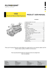
SBT-Pneumatic Sliding Balancer Track - Pneumatic Grabber ® PRODUCT USER MANUAL contents 1. Important safety instruction ........................................ 2 2. Introduction...................................................................... 2 3. Product description ....................................................... 2 4. Safety................................................................................... 3 5. CE declaration .........................................................................4 6. Area of use......................................................................... 5 7.Delivery............................................................................6-9 8. Installation.................................................................10-26 9. Installation trimming procedure...........................27-32 10. Maintenance instructions.....................................33-34 11. Cleaning and FAQ........................................................ 35 12. Disposal......................................................................... 35 13. Spare parts...............................................................36-39 Thank you for buying a Plymovent product. Before you unpack and put it into operation please read this product manual carefully, and follow the instructions. This manual should be handed over and kept by the service department after the installation. International Sales Plymovent AB Kopparbergsgatan 2 SE-214 44 MALMÖ SWEDEN Tel: +46 40 30 31 30 Fax: +46 40 30 31 40 [email protected] PUM_MG-SBT_100108_EN Rev: 1.1 England Plymovent Ltd Marley Way, Southam Road Banbury, OX16 2RA, England Tel: + 44 1295 25 93 11 Fax: + 44 1295 27 17 50 [email protected] Canada Plymovent Inc 24- 1200 Aerowood Dr Mississauga, On L4W 2S7, Canada Tel: +1 (905) 564-4748 Fax: +1 (905) 564-4609 [email protected] USA Plymovent Corp. 115 Melrich Road Cranbury, New Jersey 08512, USA Tel. + 1 609 395 3500 Fax. + 1 609 655 0919 [email protected] © Plymovent AB reserves the right to make design changes. 1. IMPORTANT SAFETY INSTRUCTIONS Please read these instructions before installing the Sliding Balancer Track (hereafter called SBT) system. This will help you obtain the full benefit from the exhaust removal system you have selected. A. Read the Product user manual and Safety Instructions carefully. Failure to follow these instructions could cause a malfunction in the system or unsatisfactory performance. 2. INTRODUCTION 1.1 Identification of the product The SBT system is made up out of various different parts which together form the SBT-Exhaust Removal System. All these individual parts can be traced back to this product user manual. 3. PRODUCT DESCRIPTION B. Follow a regular service and maintenance schedule for efficient operation. The SBT system consists of a number of parts of which the Plymovent yellow and black extraction hose assembly is most visible to the user. PREFACE The extraction hose has a Safety Disconnect Coupling built in, this to protect the system against misuse. The hose is positioned in the Saddle which connects to the balancer. The balancer is connected to the aluminium track via a special trolley. This enables the balancer to move inside the aluminium profile which is positioned above and to the tailpipe side of the vehicle. Using this manual This manual is intended to be used as a work of reference for professional, well trained and authorized persons / user’s to be able to safely install, use, maintain and repair the product mentioned on the cover of this document. Pictograms and symbols The following pictograms and symbols are used in this manual: ATTENTION A remark with additional information for the user. A remark brings possible problems to the user’s attention. CAUTION! Procedures, if not carried out with the necessary caution, could damage the product, the workshop or the environment. WARNING! Procedures which, if not carried out with the necessary caution, may damage the product or cause serious personal injury. WARNING! Denotes risk of electric shock. WARNING! Important warning to prevent fire. Service and technical support For information about specific adjustments, maintenance or repair jobs which are not dealt with in this manual, please contact the supplier of the product. He / she will always be willing to help you. Make sure you have the following specifications at hand: - The SBT Pneumatic product user manual PUM_SBT_091102_EN The aluminium profile is designed to a three (3) section principle of which two (2) sections have open areas, one on the underside and one on the overside. The overside open area is used for positioning the support legs, duct and exhaust hose connector and the release valve. The underside open area is used for positioning the end stops and for the sliding the trolley. Method of use: An automatic, pneumatic controlled exhaust gas extraction system, specially designed for fire and rescue vehicles with low level, side exhaust pipes. The system is used to remove the poisonous petrol and diesel gas fumes direct at the emission source, the exhaust pipe. When the vehicles are on their way out of the station, the extraction hose, connected to the exhaust by a special device called a Grabber®, moves along with the vehicle. Poisonous diesel gases pass from the Grabber®, up the extraction hose and into the ducting and extraction fan before escaping to the atmosphere. As the vehicles drive out through the doors, the trolley moves over a release valve on the track, which releases the air pressure in the Grabber® allowing it to disconnect the exhaust pipe. On the return of the vehicle to the station, The SBT Pneumatic Grabber® is easily re-connected to the exhaust pipe. At the same time the fan automatically starts up and the vehicle continues to its standard park position. WARNING! The use of exhaust removal hose is allowed for: - Moving of diesel-vehicles in- or out halls / stations. - Short time maintenance work of diesel-vehicles, but only if the engine is running on the minimum rpm. - The vehicle must leave and enter the station with a modified speed in order to avoid damage to the system and possible injury to people. 2/38 4. SAFETY General The manufacturer does not accept any liability for damage to the product or personal injury caused by ignoring of the safety instructions in this manual, or by negligence during installation, use, maintenance, and repair of the product mentioned on the cover of this document and any corresponding accessories. Specific working conditions or used accessories may require additional safety instructions. Immediately contact your supplier if you detect a potential danger when using the product. The user of the product is always fully responsible for observing the local safety instructions and regulations. Please observe all applicable safety instructions and regulations. User manual • Everyone working on or with the product, must be familiar with the contents of this manual and must strictly observe the instructions herein. The management should instruct the personnel in accordance with the manual and observe all instructions and directions given. • Never change the order of the steps to perform. • Always keep the manual with or near the product. Pictograms and instructions on the product (if present) • The pictograms, warning and instructions attached to the product are part of the safety features. They must not be covered or removed and must be present and legible during the entire life of the product. • Immediately replace or repair damaged or illegible pictograms, warnings and instructions. Users • The use of this product is exclusively reserved to authorized, trained and qualified users. Temporary personnel and personnel in training can only use the product under supervision. • Use common sense. Stay alert and keep your attention to your work. Do not use the product when you are under the influence of drugs, alcohol or medicine. • The product is not designed to be installed or operated by persons with limited physical, sensory or mental issues and / or limited knowledge of the system, the trained person is responsible to supervise the operation and give possible directions. • Be aware that no person is within a range of 1 (one) meter besides the vehicle when it leaves the station, and no persons are allowed in the station entrance, to avoid injury. • The system is not to be played with. Intended use (1) The product has been designed as an exhaust removal system using the Grabber® coupling system. Using the product for other purposes is considered contrary to its intended use. The manufacturer accepts no liability for any damages or injury resulting from such use. The product has been built in accordance with state-of-the-art standards and recognized safety regulations. Only use this product when in technical perfect condition in accordance with its intended use and the instructions explained in the user manual. PUM_SBT_091102_EN WARNING Do not attempt installation of this system unless you are familiar with the necessary tools, equipment, utility connections and potential hazards. Installation should be performed only by a qualified service provider. Failure to do so could result in reduced performance of the unit, serious personal injury or death. WARNING PRODUCT MAY CONTAIN SHARP EDGES Use care when servicing and installing the system. Failure to do so could result in minor personal injury. Technical specifications The specifications given in this manual must not be altered. If the hose (air supply of suction hose) is damaged please contact you supplier for service. When the air supply hose is broken, disconnect the system from the pressurized air system and call you supplier. Modifications Modifications of (parts of) the system / product is not allowed. Product combinations When the product is used in combination with other products or machines the safety instructions in this manual will remain valid as well as the safety instructions in the manuals of the other combined products. (1) The ”intended use” in accordance with EN 12100-1 is the use of he technical product in accordance with the manufacturers description including its statements in the sales brochure. In case of doubt, this is of use, which can naturally be derived from the design, construction and operation of the product. Intended use also includes compliance with the instructions in the manual. WARNING! FIRE HAZARD! Never use the product for: Extraction i.e. filtering of sigaretes sigars, oil rags or any other burning particles, objects or acids. CAUTION! Please apply and use the pre-described and normal personal protection devivices during installation and during service of the system in order to avoid injuries. This also applies to the persons who enter the work area during installation or service activities. 3/38 Installation • The installation of the products should only be performed by trained and authorised persons. For other persons and to be trained persons the products should only be handled under supervision of a responsible and authorised person when installing. • Please use appropriate lifing materials and equipment when working in an area over 2m / 6.5 feet. • Please ensure that, on the side of the vehicle were the system is installed, no persons are present in an area of 1 (one) meter under and / or around the SBT system and /or between the vehicle and the entry / exit door when the vehicle exits the building. This way possible injuries can be avoided by a possible backwards motion of the Grabber® in the direction of the station and park position. • Never install the product in front of entries, exits or passage ways which are to be used by emergecy services. • Check before installation if the structure of the wall / roof is stabile enough to hold the components which are to be attached to it. • Use common sense. Stay alert and keep your attention to your work. Do not use the product when you are under the influence of drugs, alcohol or medicine. Service, maintenance and repairs • Observe the maintenance intervals given in this manual. Overdue maintenance can lead to high costs for repair and revisions and can render the guarantee null and void. • Always use tools, materials, lubricants and service techni- ques which have been approved by the manufacturer. Never use worn tools and do not leave any tools in or on the product. • Safety features which have been removed for service, maintenance or repairs, must be put back immediately after finishing these jobs and it must be checked that they still function properly. • Please ensure that no vehicle enters or exits the station during the service, maintenance and repair activities. Tools These tools are needed to install the Plymovent System: - Power drill - Battery operated power drill - Alllen key set - Phillips srewdriver set - Measuring tape Please note that additional tools and machines may be needed depending on the installation situation (installation height, space available etc). 5. CE DECLARATION CE declaration of conformity for machinery • Air, which might contain health hazardous components, such as chrome, Nickel, Beryllium, Cadmium, Lead etc. should never be recycled. This type of air must always be removed from the working area. Use • Inspect the product and check for damages. Verify the functioning of the safety features. • Check the working area. Please keep unauthorised persons away from the working area. • Protect the product against water and humidity. • Make sure the room is always sufficiently ventilated; this applies especially to confined spaces. ”We, Plymovent, Kopparbergsgatan 2, SE-214 44 Malmö, Sweden, herewith declare, on our own responsibility, that the product(s): - Sliding Balancer Track System is/are in conformity with the following harmonized standard(s) and/or other such normative documents + amendments, if any: DIN 14572:2002 DIN 31000/A1:2007 DIN EN 12100-1/A1:2009 DIN EN 12100-2/A1:2009 ZEK 01.02-08 • Make sure that the workshop, in the vicinity of the product, contains sufficient approved fire extinguishers if any elctronics, such as control boxes, are used. Alkmaar, the Netherlands, 18-06-2010 • The user of the product always has full responsibility for the correct execution of the safety guidelines and instructions. These are all the safety guidelines and instructions which apply to the use of the system. C.J.M. Knijn Chief Operations Officer ATTENTION! After shutting down the ventillation system wait minimal 10 seconds before handeling the system and prodcuts when performing service, maintenance and / or repairs. PUM_SBT_091102_EN ATTENTION! Service, Maintenance and Repairactivities shall only be performed (in line with TRGS 554) by authorized, trained and qualified personnel taking into account the applicable working practices and safety regulations. 4/38 6. AREA OF USE The SBT system is designed to be used in Fire- and Rescue Stations where there is one (1) vehicle parked behind the entry / exit door. ATTENTION The SBT System is designed to operate under standard vehicle performance conditions. Re-generation is not considered to be a standard vehicle performance condition. SBT is designed to handle exhaust gas temperatures of +150°C / 302F (short time +170°C / 338F) and an airpressure of max 8,0 bar. USA hose is 400°F continuous and 500°F intermittent. WARNING! - Do not put hands or other body parts in the Grabber®. Only activate the Grabber® when placed on the tailpipe. Do not bend over in the direction of the tailpipe when positioning the Grabber® to the vehicle. Exhaust gasses can enter the breathing zone of the user. Side view Duct/Hose Connector 1,8 m / 6ft End stop with rubber shock absorber Support leg Track 1,8 m / 6ft 11.5 ft - 14.8 ft 3,5m-4,5m Trolley Grabber® Track section Overview Support section Stabilizor section Trolley section max 0.5m / 20” PUM_SBT_091102_EN 5/38 7. DELIVERY The track is delivered in parts together with a product manual. Fan, fan control device and compressed air supply need to be added individually depending on application. Vertical mounting Horizontal mounting The SBT, in all different versions, is built out of a few standard components which will be described in this section. Support leg The aluminium support leg is used for both vertical and horizontal mounting. The standard length is 5790 mm / 19 feet and it has to be cut to proper lengths during installation. The dimension of the support leg is 50x50x2,5 mm / 2x2x0.1 inch Prod. No. SBT-SL Art. Nr: 8120-1011 Side brace There are three different lengths available: - 500 mm / 20 inch - 750 mm / 30 inch -1800 mm / 70 inch The brace can be mounted separately or in pairs using the same brackets. PUM_SBT_091102_EN Prod. No. SBT-SB-S, 500mm Art. Nr. 8140-1011 Prod. No. SBT-SB-M, 750mm Art. Nr. 8141-1011 Prod. No. SBT-SB-L, 1800mm Art. Nr. 8142-1011 6/38 7. DELIVERY Side brace clamp kit The kit includes two aluminium brackets for one or two side braces. Prod. No. SBT-SBCK Art.No. 8130-1011 Adjustable mounting kit (vertical) The two brackets are exactly the same. They can also be used if the roof is angled and they can be mounted in both directions. Maximum angle is 30 degrees. 1 2 3 In order to fasten the bracket to the support leg three through holes have to be drilled. Start by drilling hole ”1” and ”2”. Then adjust the bracket to an exact position and fix it by drilling a third hole ”3”, using the most centrered hole from the top row. Prod. No. SBT-MKV Art. No. 8150-1011 Adjustable mounting kit (horizontal) The bracket that shall be used against the wall is the same as for the vertical kit (see above) but on the track side there is a new bracket which is adjusable in relation to the support leg. When the bracket is fixed in the right position two through holes in the support legs two holes are drilled through the support leg using the bracket as a template. Prod. No. SBT-MKH Art. No 8160-1011 PUM_SBT_091102_EN 7/38 7. DELIVERY Universal mounting cross The cross can be used if the wall or roof is angled but the only available beam is going in the "wrong" direction for the standard bracket. The position of the cross is between the bracket and the wall. Prod. No. SBT-UMC Art. No 8170-1011 SBT Track The SBT track is delivered in 2 lengths: SBT-Track 5790mm / 19 feet SBT-Track 2895mm / 9.5 feet Prod. No SBT-TRACK Art. No. 8332-1011 Prod. No. SBT-TRACK-1/2 Art. No. 8331-1011 Hose kit There are 7 hose kits available which also contents the hose connector. Hose - Temp.resistance +150°C. - Hose diameters are 100 mm / 4” or 125 mm/ 5” - Length 6m / 19.6 feet or 10m / 33 feet - Grabber® 120mm / 4.7” or 160mm/ 6.3” The different hose packages which contain the following parts: - Transition parts and regulator - Exhaust removal hose (+150°C / 302 F) - USA hose is 400°F continuous and 500°F intermittent. - Hose saddle - Safety disconnect - MFD valve - Teflon air hose with complete Grabber® nozzle - Grabber® nozzle 100mm / 4” or 120mm / 5” or 160mm / 6.3 ” PUM_SBT_091102_EN Prod. No. SBT-HK-100-6-100 SBT-HK-100-6-120 SBT-HK-100-6-160 SBT-HK-100-10-120 SBT-HK-100-10-160 SBT-HK-125-6-160 SBT-HK-125-10-160 Art. No. 8215-1011 8220-1011 8225-1011 8230-1011 8235-1011 8240-1011 8245-1011 8/38 7. DELIVERY Splicing sleeve If the track is longer than 5790 mm / 19 ft a splicing sleeve must be used. Common material Common materials that are always included are gathered under product no "SBT-KIT Pneumatic". Material included in the kit are: - Release valve - End stop - Security tape marking - Trolley - Balancer - Balancer locking cable Prod. No. SBT-Slice Prod. No. SBT-KIT Pneumatic PUM_SBT_091102_EN Art. No. 515633 Art. No. 8175-1011 9/38 8. INSTALLATION BACK-IN MEASUREMENT PROCEDURE WARNING PRODUCT MAY CONTAIN SHARP EDGES Use care when installing and servicing the products. Failure to do so could result in minor personal injury. Please determine the position of: 1. 2. 3. Exhaust pipe Gate / Exit door Distance Gate / Exit door vs the exhaust pipe 1) Determine the location of the exhaust pipe (1) on the vehicle; which side of the vehicle it is positioned on. i.e. were does the exhaust exit the vehicle and that diameter does the exhaust pipe have. CAUTION Be sure to order the right Grabber® dimension. If a incorrect version is used on the tailpipe, the system could be damaged (too small Grabber®) or will disfunction (system will not be airtight, exhaust gasses can enter the premises) 2) Measure the height and width of the gate (2). Check what type of gate: - Slidegate - Overhead gate - Other type Check at what height the track can be installed. 3) Measure the distance between the gate and the exhaust pipe (3), this is the required length of the SBT-track. Check before installation that this is the minimum required length of the SBT in a vehicle back-in application situation. The recommended distance from the end of the track to the door(s) is 1.8m. / 6 ft 2 PLAN VIEW PUM_SBT_091102_EN 1 3 10/38 8. INSTALLATION DRIVE-THROUGH MEASUREMENT PROCEDURE WARNING PRODUCT MAY CONTAIN SHARP EDGES Use care when servicing unit. Failure to do so could result in minor personal injury. Please determine the position of: 1. 2.1 2.2 3. Exhaust pipe. Entrance door. Exit door. Distance between Entrance door / Exit door. 1) Determine the location of the exhaust pipe (1) on the vehicle; which side of the vehicle it is positioned on. i.e. were does the exhaust exit the vehicle and that diameter does the exhaust pipe have. CAUTION Be sure to order the right Grabber® dimension. If a incorrect version is used on the tailpipe, the system could be damaged (too small Grabber®) or will disfunction (system will not be airtight, exhaust gasses can enter the premises) 2.1) and 2.2) Determine the gate height and width. Check what type of gate: - Slidegate - Overhead gate - Other type Check at what height the SBT-track can be installed. 3) Measure the distance between the gate and the exhaust pipe (3), this is the required minimal length of the SBT-track. Check before installation that this is the minimum required length of the SBT in a vehicle back-in application. The recommended distance from the end of the track to the door(s) is 1.0m / 3.3 ft PLAN VIEW 3 1 2.2 PUM_SBT_091102_EN 2.1 11/38 8. INSTALLATION SBT-TRACK LOCATION PROCEDURE 1. 2. 3. 4. 5. 6. WARNING PRODUCT MAY CONTAIN SHARP EDGES Use care when servicing unit. Failure to do so could result in minor personal injury. SBT-Profile Exhaust pipe Door Height of track Distance to vehicle The longitudinal track CAUTION Be sure to order the right Grabber® dimension. If a incorrect version is used on the tailpipe, the system could be damaged (too small Grabber®) or will disfunction (system will not be airtight, exhaust gasses can enter the premises) The SBT-track (1) is mounted at a height (4) between 3,5m / 11.5 ft and 4,5m / 15 ft over the floor on the side where the vehicles exhaust pipe (2) is situated. The track is often mounted immediately under a sectional door (3) with a clear height from the track to the door of 100mm / 4” to 150 mm / 7”. The SBT-track is placed 160mm / 6.3” to 508mm / 20” (5) from the truck-side of the vehicle. The recommended distance from the end of the track to the door(s) (6) is 1.0m / 3.3 ft ELEVATION VIEW 1 3 4 2 PLAN VIEW 3 1 5 6 PUM_SBT_091102_EN 12/38 8. INSTALLATION WARNING PRODUCT MAY CONTAIN SHARP EDGES Use care when servicing unit. Failure to do so could result in minor personal injury. VERTICAL SUPPORT LOCATION 1. 2. 3. Front support: Rear support: Additional support(s) ATTENTION! See side view for minimum load capacity on the fixing bolts. 1) The position of the front support (1) is determined first. The door is the initial point for the location of this. A open door requires a margin of 50mm / 2” for the support. Next to this the distance from the front support to the start of the profile should be not larger then 1,5m / 5 feet. If this is not possible please use a wall mounting bracket to attach the front solidly. CAUTION Before lifting the rail be sure that, the trolley is fixed in its place, using both end stops. This to avoid injury when trolley moves if the rail is uneven lifted. 2) The rear support (2) is placed approximately 1000 mm / 40” from the rear of the SBT-profile. 3) Depending on the lenght of the SBT track additional supports have to be mounted. The normal distance between the supports is approximately 3 meter / 10 feet. SIDE VIEW 120 Kg/Bolt 140 Kg/Bolt 140 Kg/Bolt 2 3 1 BAY DOOR 1000 mm 50 mm / 2” PUM_SBT_091102_EN 13/38 8. INSTALLATION WALL SUPPORT LOCATION PROCEDURE 1. 2. 3. WARNING PRODUCT MAY CONTAIN SHARP EDGES Use care when servicing unit. Failure to do so could result in minor personal injury. SBT-track Support leg Additional Brace CAUTION Before lifting the rail be sure that, the trolley is fixed in its place, using both end stops. This to avoid injury when trolley moves if the rail is uneven lifted. 1) The position of the SBT track (1) is determined first. Please see to it that the profile is positioned within the gap of the open door. The door is the initial point for the location of this. 2) The support leg (2) is then measured versus the mounting position at the wall. 3) Depending on the lenght of the SBT track additional supports have to be mounted. The distance from the first installation bracket to the front and respectively the end of the rail should be minimal 1,5m / 5 feet. The distance between the side of the truck (tailpipe) and the SBT profile should be maximal 500mm / 20 inch. 3 2 1 max 500 mm / 20” PUM_SBT_091102_EN 14/38 8. INSTALLATION HOSE CONNECTION BACK-IN LOCATION PROCEDURE 1. 2. 3. 4. 5. 6. 7. SBT-Profile Hose connection / connector Distance from the door to exhaust pipe Exit door Exhaust pipe Half the distance from exit door to exhaust pipe Distance to hose connection is 600mm / 2´ to 1200mm / 4´ WARNING PRODUCT MAY CONTAIN SHARP EDGES Use care when servicing unit. Failure to do so could result in minor personal injury. CAUTION Before lifting the rail be sure that, the trolley is fixed in its place, using both end stops. This to avoid injury when trolley moves if the rail is uneven lifted. a) The hose connection (2) is positioned according to what side of the vehicle the exhaust pipe (5) is positioned on. b) The hose connection (2) is mounted on the SBT-track on the opposite side of the vehicle. c) The hose connection / connector (2) is placed at the point: calculated as followed: - Distance Exit door to exhaust pipe (3), divided by half (6), plus 500mm / 20 inch (7) This is the position of the hose connection / connector (2) relative to the exit door. (4) NOTE! It is important to have a margin on the hose length when driving in backwards please take this into account! PLAN VIEW 4 3 5 1 6 PUM_SBT_091102_EN 7 2 15/38 8. INSTALLATION HOSE CONNECTION DRIVE-THROUGH LOCATION PROCEDURE 1. 2. 3. 4. 5. 6. WARNING PRODUCT MAY CONTAIN SHARP EDGES Use care when servicing unit. Failure to do so could result in minor personal injury. SBT-track Hose connection Distance entrance gate-exit gate Entrance gate Exit gate Exhaust pipe CAUTION Before lifting the rail be sure that, the trolley is fixed in its place, using both end stops. This to avoid injury when trolley moves if the rail is uneven lifted. a) The hose connection (2) is positioned according to what side of the vehicle the exhaust pipe (6) is positioned on. b) The hose connection (2) is mounted on the SBT-track on the opposite side of the vehicle. c) At a drive-through station the hose connection (2) shall be positioned on the SBT-track (1) at the half distance, between entrance gate (4) and exit gate (5). PLAN VIEW 3 6 5 4 PUM_SBT_091102_EN 2 = 1 = 16/38 8. INSTALLATION SUSPENSION MOUNTING PROCEDURE 1. 2. 3. 4. 5. 6. 7. 8. SBT-profile Support leg Mounting clamp Carriage bolts M10x30 with washers and locking nuts Bolts M10x70 with washers and locking nuts Brackets Upper Bracket Disconnect valve bracket WARNING PRODUCT MAY CONTAIN SHARP EDGES Use care when servicing unit. Failure to do so could result in minor personal injury. CAUTION Before lifting the rail be sure that, the trolley is fixed in its place, using both end stops. This to avoid injury when trolley moves if the rail is uneven lifted. a) The support legs (2) are cut to proper lengths. b) The mounting clamp (3) with two M10x30 bolts (4) for the suspensions are inserted in the profile (1). Please observe you insert these into the correct side of the profile. Insert the Disconnect vallve bracket (8) between the first and second suspension leg. 8 c) The mounting clamp for the hose/pipe bracket, see "Hose connection mounting procedure" in this product user manual, is inserted in the profile. d) Drill two holes,in the support leg (2), one for the upper and one for the lower bracket (6). Mount the Brackets (6) to the support leg (2), the upper bracket can be adjusted by up to 30 degrees if needed. e) When the complete track (1) is adjusted correclty fix the brackets by drilling a second and a third hole through the brackets (5) into the support legs (2). Use the pre-drilled holes in the brackets (6) and fix tightly using the most centered holes. SIDE VIEW BACK VIEW 4 3 6 5 2 1 7 PUM_SBT_091102_EN 17/38 8. INSTALLATION SUPPORT LEG MOUNTING PROCEDURE 1. 2. 3. 4. WARNING PRODUCT MAY CONTAIN SHARP EDGES Use care when servicing unit. Failure to do so could result in minor personal injury. SBT-Profile Side brace Longitudinal brace Bolts M10x20 and locking nuts CAUTION Before lifting the rail be sure that, the trolley is fixed in its place, using both end stops. This to avoid injury when trolley moves if the rail is uneven lifted. a) Both side braces (2) are mounted on the same bracket. b) Longitudinal brace (3) is mounted in a separate bracket. Use M10x20 and locking nut (4), check that the support is vertical before the bolts are fastened. 4 BACK VIEW SIDE VIEW 3 2 PUM_SBT_091102_EN 18/38 8. INSTALLATION WALL SUPPORT MOUNTING PROCEDURE 1. 2. 3. 4. 5. 6. WARNING PRODUCT MAY CONTAIN SHARP EDGES Use care when servicing unit. Failure to do so could result in minor personal injury. SBT-Profile Horizontal wall support Mounting clamp Carriage bolts M10x30 with washers and locking nuts Nuts M10 with clamp for adjustment of height and side to side. Disconnect valve bracket. CAUTION Before lifting the rail be sure that, the trolley is fixed in its place, using both end stops. This to avoid injury when trolley moves if the rail is uneven lifted. a) Cut the Horizontal wall support(2) to the correct length and follow the same steps as indicated in the suspension mounting procedure for installing the wall brackets. b) Fix the mounting clamp (3) with two M10x30 bolts (4) to the SBT-Profile (1). Also insert the mounting clamp for the hose bracket (see hose connection mounting procedure). Next to this insert the disconnect valve bracket (6) between the first and second suspension leg. 6 c) Profile(1) with mounting clamps (3) and supports (2) are mounted together with washers and locking nuts M10. c) The nuts (5) are loosened to adjust the track vertical and horizontal. BACK VIEW SIDE VIEW 3 2 5 5 1 4 PUM_SBT_091102_EN 19/38 8. INSTALLATION HOSE CONNECTION MOUNTING PROCEDURE 1. 2. 3. 4. SBT-Profile Hose connection Mounting clamp Carriage bolts M10x30 with washers and locking nuts WARNING PRODUCT MAY CONTAIN SHARP EDGES Use care when servicing unit. Failure to do so could result in minor personal injury. a) The mounting clamp (3) with two M10x30 bolts (4) for the hose connection are inserted in the profile (1) together with the mounting clamps for the support legs, see ”support legs mounting procedure” in this product user manual. b) The hose connection (2) is tightened in place with washers and locking nuts. Please note the hose connection should be opposite the vehicle position of the rail. PLAN VIEW ELEVATION VIEW 2 2 3 4 1 PUM_SBT_091102_EN 1 20/38 8. INSTALLATION TRACK SPLICE ATTACHMENT PROCEDURE 1. 2. 3. WARNING PRODUCT MAY CONTAIN SHARP EDGES Use care when servicing unit. Failure to do so could result in minor personal injury. SBT-track Splicing sleeves Bolts M6*50 and locking nuts a) The track splicing sleeves (2) shall be fixed in position on each side of the SBT-track (1) with a clamp. b) Be sure you have the SBT-track (1) in equal length covered by the splicing sleeve (2). c) Check that you have the splicing sleeves in equal position. d) Drill 6mm holes through the SBT-track using the pre-drilled track splicing sleeve holes. e) Assemble the splicing sleeve with the four bolts M6*50 and the locking nuts (3). ELEVATION VIEW SIDE VIEW 1 1 2 PUM_SBT_091102_EN 2 3 3 21/38 8. INSTALLATION TAPE/LABEL APPLICATION PROCEDURE 1. 2. 3. SBT-track Hazard tape Plymovent sticker a) The SBT-track (1) can be taped hanging in the support legs, but is easiest taped before installation. b) Clean the SBT-track with a cloth and solvent before putting on tape and stickers. c) The SBT-track shall be taped with supplied hazard tape (2) on both sides. The supplied Plymovent stickers (3) are applied on both sides of the SBT-track (1), on the hazard tape (2), 600mm / 24" from exit end. SIDE VIEW 3 1 2 HOSE ALIGNMENT PROCEDURE 1. SBT hose: 2. Grabber® nozzle: 3. MFD valve: 4. Hose saddle: The exhaust hose assembly shall be aligned at installation as follows: 1. The exhaust hose assembly is straightened out on the floor with the Grabber® pointing upwards against the door and facing upwards. 2. Reposition if nessecary and align the Grabber® (2), the MFD valve (3) and the hose saddle (4) in the show position. 3. After hose alignment mount the hose (1) on the hose connection with the Grabber® pointing upwards against the door. 1 PUM_SBT_091102_EN 4 3 2 22/38 8. INSTALLATION BALANCER/SADDLE MOUNTING PROCEDURE 1. 2. 3. 4. 5. 6. 7. 8. SBT-profile Trolley with disconnect plate Balancer with safety chain and locking cable. Measurement, safety chain to floor minus 250mm Measurement, saddle to Grabber® nozzle Grabber® nozzle Saddle ring Grabber® nozzle 250mm height over floor WARNING PRODUCT MAY CONTAIN SHARP EDGES Use care when servicing unit. Failure to do so could result in minor personal injury. a) The trolley (2) is slided in to the SBT-profile (1). b) The balancer (3) is hung in the forward/lower suspension hole with the wire towards the door, and the safety chain facing towards the back of the parking area. Please see balancer instructions for the correct settings of the balancer. c) The Balancer locking cable is connected between the hose saddle and the trolley. d) Measure the distance between the safety chain and the floor and subtract 250mm (4). e) This measurement is used to determine the measurement (5) from the Grabber® opening to the saddle ring (7). f) The saddle is to be aligned according to: "Hose alignment procedure" please see chapter Trimming Procedure of this Product User Manual. 2 3 1 Exit 6 7 4 5 Floor PUM_SBT_091102_EN 8 23/38 8. INSTALLATION HOSE/Grabber® INSTALLATION PROCEDURE 1. 2. 3. 4. 5. SBT-track height over floor (minimum 3500mm / 11,5 ft) Hose connection Hose loop height Grabber ® nozzle height over floor Hose saddle WARNING PRODUCT MAY CONTAIN SHARP EDGES Use care when servicing unit. Failure to do so could result in minor personal injury. a) The SBT-track height (1) is a major factor in determining the hose loop height (3) b) The hose connection (2) location also affects the loop height. (also see Trimming procedure) c) Hose loop height (3) should not be less than 2,0m / 6,5ft not to be in the way of fire personnel d) The hose saddle (5) should be placed in about half the distance between the Grabber® nozzle and hose connection e) The distance between the floor and the Grabber® nozzle (4) must be approx 250mm / 10” 2 5 1 3 4 PUM_SBT_091102_EN 24/38 8. INSTALLATION PC-500 PRESSURE SWITCH INSTALLATION PROCEDURE 1. 2. 3. WARNING PRODUCT MAY CONTAIN SHARP EDGES Use care when servicing unit. Failure to do so could result in minor personal injury. PC-500 pressure switch Drilling machine with 10mm / 0.4” drillbit Measurement from ducting/hose approx. 100mm / 4” a) Drill a hole in the ducting using a drilling machine (2) above the riser bracket. b) Mount the pressure switch (1) by screwing it into the ductwork. Turn as long as to the moment that the sensor is tight and both connection points are upwards. Connect the electric wires with the supplied connection tags. Or connect the PC-500 pressure switches to the wireless transmitters. Tip: when using more pressure sensors these can be mounted parallel. c) For connection to the control box (various control boxes applicable) please see Prodcut User Manual of the relevant control box. 2 1 10mm / 0.4” 3 PUM_SBT_091102_EN 25/38 9. INSTALLATION END STOP ATTACHMENT/LOCATION PROCEDURE 1. 2. 3. 4. 5. SBT-track End stop with rubber shock absorber Mounting clamp Carriage bolts M8 with washers and locking nuts Endstop WARNING PRODUCT MAY CONTAIN SHARP EDGES Use care when servicing unit. Failure to do so could result in minor personal injury. a) Endstop with rubber shock absorber (2) is mounted at the exit end of the SBT-track (1). b) The end stop with rubber shock absorber (2) is pushed in the SBT-track (1) with the mounting clamp (3) on the underside of the track, and then the locking nuts on the carriagebolts (4) are tightened. Make sure the locking nuts are tightly fastened c) The endstop without shock absorber (5) is mounted the same way at entrance/parking end of the SBT-track. d) The position of the end stop should be were the balancer needs to stop in order to realise the Grabber® disconnect at the exit door. SIDEVIEW 1 1 5 2 3 3 4 4 BACK VIEW 1 2 3 4 PUM_SBT_091102_EN 26/38 9. INSTALLATION - TRIMMING PROCEDURE 1. Release valve: 2. Bolts M5x25 and locking nuts: 3. Release valve knee: 4. Release valve bracket: 5. Release plate: WARNING PRODUCT MAY CONTAIN SHARP EDGES Use care when servicing unit. Failure to do so could result in minor personal injury. The release valve (1) is delivered for assembly to the SBTProfile when using a RIGHT side exhaust. When installing the SBT-Profile for a LEFT side exhaust the release valve (1) has to be changed as follows: Unscrew the bolts and nuts (2), turn the valve with the knee (3) pointing to the gate, reassemble the valve on the bracket (4). Check that the release plate (5) pushes the release valve so that it nearly bottoms out with approximately 1 mm clearance. TRUCK-SIDE VIEW, RIGHT SIDE EXHAUST TRUCK-SIDE VIEW, LEFT SIDE EXHAUST EXIT DOOR 2 EXIT DOOR 1 4 4 1 2 3 3 5 5 PUM_SBT_091102_EN 27/38 9. INSTALLATION - TRIMMING PROCEDURE THE HOSE 1. 2. 3. 4. 5. WARNING PRODUCT MAY CONTAIN SHARP EDGES Use care when servicing unit. Failure to do so could result in minor personal injury. SBT-hose assembly: Grabber® ® nozzle: 0,5-1m of wire out of balancer: Hose connection: Hose loop height: a) The SBT- hose assembly (1) is mounted/trimmed up with the Grabber® nozzle (2) at a height of 0,5m /20" above the floor when the Grabber® reaches the exit door. b) At correct length of the exhaust hose, 0,5-1m of wire should be out of the balancer (3) when the Grabber® ® is at disconnect point. c) The exhaust hose is cut to length with a knife and a wire cutter if the length needs to be shortened. d) The hose loop height (5) should not be less than 2000mm in order not to be in the way of fire personnel. 4 3 2 1 5 Grabber® ® at disconnect position PUM_SBT_091102_EN Grabber® ® connected to vehicle 28/38 9. INSTALLATION - TRIMMING PROCEDURE 1 Release valve: 2. Release plate: 3. Bolt M6x20mm and washer. 4. Mounting clamp: 5. Toggle joint of the release valve. WARNING PRODUCT MAY CONTAIN SHARP EDGES Use care when servicing unit. Failure to do so could result in minor personal injury. The release valve (1) is mounted on the truck-side of the SBT-profile with the toggle joint (5) pointing towards the gate, approximately 1800 mm from end of track. The valve is fitted with the mounting clamp (4), bolt M6x20mm and washer (3). Check that the release plate (2) pushes the release valve so that it nearly bottoms, appr. 1 mm clearance. TRUCK-SIDE VIEW BACK VIEW 3 1 4 5 1 Ducting 2 2 Hose PUM_SBT_091102_EN 29/38 9. INSTALLATION - TRIMMING PROCEDURE BALANCER SETTING PROCEDURE 1. Balancer 2. Balancer safety chain WARNING The balancer is delivered under tension. Be carefull when fine tuning the balancer. The balancer is factory delivered at a pre-tension. In order to make sure the balancer is functioning optimally please follow the following procedure: a. After every component of the system is installed, the balancer tension must be adjusted to its final setting. Increase the spring tension by turning the balancer counter- clockwise until the rubber stop hits the balancer. 2 1 b. Add two more ”quarter-clicks” to ensure full retraction of the balancer cable. It’s possible the balancer tension needs to be fine-tuned after total system is installed and a test run is done. Balancer tuning: Problem: The Grabber® ® nozzle hits the ground after disconnection. Solution: Increase the balancer tension with 1 (one) ”quarter-click”. Problem: The ”swing-back” of the hosedrop after disconnection is too extreme. Solution: Decrease the balancer tension with 1 (one) ”quarter-click”. PUM_SBT_091102_EN 30/38 9. INSTALLATION SDCH - TRIMMING PROCEDURE 1) The distance between the floor and the Grabber® nozzle (1) should be 25-30cm / 10”-12” from finished floor 2) The distance between the floor and the safety disconnect handle (2) should be 1 meter / 3.3 feet from finished floor For the Pneumatic system - Determine the position of the SDCH in the hose drop (approx 1 meter / 3.3 feet above the floor). - Unscrew the upper and lower plastic parts of the new SDCH (6 screws on the bottom of the handle). - Position and fix the upper half of the new SDCH to around the upper hose. * Make sure the position of the valve is on the opposite site of the vehicle. * Make sure the rubber cover for the hose clamp is fitted. - Insert the two 6mm air lines through the rubber grommets in the upper aluminium flange. - Connect the two 6mm air lines into the MFD valve (P on the valve is for the 1 bar Grabber® supply, the other tube fitting on the same side of the valve is for the release signal). See image to the right: - If the two 6 mm tubes are right connected to the valve, (check function) re-assemble the two plastic parts together with the same 6 screws. Hereby attaching the lower half of the SDCH to the upper half (including the lower aluminium flange). - Insert the lower flange in the hose and tighten the hose clamp. - Cover the hose clamp with the rubber protective sleeve when the hose clamp is tightened. - Insert the lower flange in the lower hose and tighten the hose. - Cover the hose clamp with the rubber protective sleeve when the hose clamp is tightened. - Push the 8mm Grabber® line in the hole, just underneath the valve in the plastic lower part of the SDCH. - Switch the compressed air on. CAUTION! Please apply and use the pre-described and normal personal protection devivices during installation and during service of the system in order to avoid injuries. This also applies to the persons who enter the work area during installation or service activities. 2 1 Floor Pneumatic version of the Safety Disconnect handle In case of maintenance or adjustment of the Pneumatic valve please note the following: Upper fitting Lower fitting Grabber® connection Release A P S A R 1 bar in 8 bar in 1 bar out (leave open) R P S ATTENTION! Please ensure that the compressed air delivered to the Plymovent system is dry and clean. Failure to supply this air may result in failure of the system. PUM_SBT_091102_EN 31/38 9. INSTALLATION - TRIMMING PROCEDURE 1. SBT-Profile: 2. Release valve 3. Unregulated air for release valve (6 - 8 bar) 4. Regulated air for Grabber® ® (coloured hose 0,7-1,0 bar): CAUTION Please test if the pressure air hoses are connected into the system in the correct way ( 0,7-1,0 bar) before you pressurise the system. Also test the pressure air system after the safety disconnect has released. 5. Regulator with manometer 6. Compressed air feeder (6 - 8 bar) 7. MFD-valve ATTENTION! Please ensure that the compressed air delivered to the Plymovent system is dry and clean. Failure to supply this air may result in failure of the system. The compresed air (max. 8 bar) is connected to the compressed air feeder (6). Unregulated air (3) is connected via the 8mm air hose to the release valve (2). This unregulated air is then connected from the release valve through the rubber grommet on the hose holder down through the exhaust hose and connected to fitting S on the MFD valve.” Regulated air (4) is connected from the regulator (5) through the rubber inlet in the hose holder down through the exhaust hose to the side of the MFD-valve (7). Use the colours of the air hoses for orientation. Pneumatic version of the Safety Disconnect handle In case of maintenance or adjustment of the Pneumatic valve please note the following: Upper fitting Lower fitting Grabber® connection Release P S A R 1 bar in 8 bar in (leave open) From the MFD-valve (7) an 8mm air hose connects down to the Grabber®. A PLAN VIEW R P S TRUCK-SIDE VIEW 1 4 5 2 2 3 3 3 8 mm 6 mm 7 3 6 3 4 PUM_SBT_091102_EN 32/38 10. MAINTENANCE INSTRUCTION Inspection and maintenance: Inspection/maintenance shall be done according to following scedule: 0-500 500-1500 1500-3000 3000 + turn-outs/year turn-outs/year turn-outs/year turn-outs/year every 16th week every 12th week every 8th week every 4th week 1. Check the compressed air systems mechanical attachments and leakages on couplings, realease valve and regulator. ATTENTION! a. Service and maintenance only to be done by qualified and trained persons ( in EU according to TRGS 554. b. Use sufficient climbing gear and safety guards when working on a higher level than 2.0 meter. c. Only carry out service and maintenance when the system is fully disconnected from mains. d. Be sure no vehicle can enter the station/bay when carrying out service/maintenance. 2. Check/adjust the air pressure (max 1.0 bar). 3. Remove the hose assembly from the balancer and check the hose, compressed air hoses, suspension halter, MFD-valve and Grabber® . The safety disconnect coupling should be disassembled and cleaned. The hose assembly should be aligned prior to mounting see " Alignement/mounting of hose assemby" in the mounting instructions. 1 2 3 PUM_SBT_091102_EN 33/38 10. MAINTENANCE INSTRUCTION Inspection and maintenance: Continued: 4. Check the correct attachment of the safety chain attaching the balancer to the trolley. 5. Ensure the hose has the correct distance to the floor. Spring tension must be adjusted when required. 6. Check the correct movement of the trolley, correct function of the release valve and end-stops. 7. Check that the trolley trip plate activates the release valve correctly. The release valve must be activated to 1mm from bottom position. 8. Check the balancer - see separate manual 9. Disconnect the hose from the balancer and inspect the hose for any faults. 10. Check if the saddle is correctly supporting the hose. 11. Disassemble the Safety disconnect and clean. 12. Ensure the hose is in the correct installation position ( see hose connection procedure). 4 7 6 8 6 6 8 8 PUM_SBT_091102_EN 34/38 11. Cleaning and FAQ ATTENTION Do not use solvents to clean the system. HOSE PACKAGE Clean with water and a soap-solution. AIR-COMPONENTS Use compressed air to blow equipment clean. SBT-RAIL AND SUSPENSIONS Clean with water and a soap-solution You observe that.... The Grabber® does not connect tightly to the tailpipe Why ? The pressure in the Grabber® is not high enough. The inflation time of the Grabber® takes a long time You cannot operate the MFD operating valve good enough. Leakage in the pressure air system The MFD valve is not connected correctly. What to do ? The pressure at the SBT-Presure regulator should be increased (0,7-max 1,0 Bar) Seal the leakage. Un-twist the exhaust removal hose either at the connection between the hose and duct, or saddle which should make operating the MFD valve possible again. The Grabber® is dragging over the floor or is is pushed back too far. The Grabber® is hanging too low, the Disconnect the saddle and reposition balancer force is too strong. it so that the hose is off the floor. Or adjust the balancer force on the balancer. The Grabber® is transported out The disconnect point is too far forThe release valve or (and) the end of the Garage too far and the hose ward. stop should be moved further back swings back forcefully. onto the rail. The Grabber® opens when the vehic- The release valve releases air when The MFD pressure valve can be stuck, les drives into the station. the vehicle is moved into the station. or the release valve on the trolley is positioned too high. The Grabber® does not close while The pressure air line in the hose is Disconnect the hose and check the the manometer indicates there is twisted and / or blocked. pressure air lines in the hose and unpressure. twist / unblock them. 12. DISPOSAL The level of Service and Maintenance on the Plymovent systems is relatively low. The Service and Maintenance department of Plymovent consists of well trained personnel who can offer you a Service and Maintenance contract which ensures your system will function for many years to come. Disposal - Cardboard packaging - Aluminium profile - Hose - Grabber® Nozzle PUM_SBT_091102_EN Recycle Recycle Rest waste Rest waste When dismantling the system please ensure to follow the similar safety precautions as mentioned in this manual for installation. Dismantling must be done contrary to the installation instructions. Dismount loose parts before the rail is dismounted. 35/38 14. SPARE PARTS 7 6 2 5 1 8 3 4 9 10 11 22 21 23 24 See separate Balancer manual 20 26 PUM_SBT_091102_EN 25 36/38 14. SPARE PARTS 33 31 29 32 30 34 35 39 36 37 35 38 PUM_SBT_091102_EN 37/38 14. SPARE PARTS BSAB No: T3.1 SPARE PARTS LIST Ser. No: SBT / RR Date: Dec -10 SBTP © Copyright: All right reserved. All information within this printed matter may not be reproduced, handed over, copied, xeroxed or translated into another language, in any form or any means without written permission from PlymoVent AB. PlymoVent AB reserves the right to make design changes. Produkt No: A All models B SBTP-6-100-160 C SBTP-6-100-120 D SBTP-6-100-100 E SBTP-6-125-160 F SBTP-9-100-160 G SBTP-9-100-120 H SBTP-9-125-160 I J Abreviations X = Order as requiered, state requiered length. Decription All models of SBTP Pos Art. No: 1 987990-Z 988451-Z 988006-Z 988469-Z 2 987 842 988 576 3 4-1417 4-1416 4-1415 4-1418 4 991 299 991 125 991 109 5 512 616 512 624 6 985 887 7 985 895 8 985 960 9 961 458 961 490 10 961 474 961 458 11 905 550 905 555 15 993 329 16 516 740 17 516 856 18 993 881 19 993329-Z 20 516 476 21 994 137 22 516 980 23 993 998 24 994 012 25 969 691 PUM_SBT_091102_EN A B C D E F G H 1 1 1 1 1 1 1 1 1 1 1 1 1 1 1 1 1 1 1 1 1 1 1 1 1 1 1 1 1 1 1 1 1 X X X 1 1 1 1 1 1 1 1 1 1 1 1 1 1 1 1 1 1 1 1 1 1 1 1 1 1 1 I Models with vertical support legs Models with horizontal support legs J Description Exhaust hose Ø100 L=6M Exhaust hose Ø125 L=6M Exhaust hose Ø100L=10M Exhaust hose Ø125 L=10M Exhaust hose Ø100L=0,6M Exhaust hose Ø125 L=0,6M Grabber bend 100/160 Grabber bend 100/120 Grabber bend 100/100 Grabber bend 125/160 Grabber Bladder 160 Grabber Bladder 120 Grabber Bladder 100 Note Hose Saddle Ø 100 Hose Saddle Ø 125 Compressed air hose White Ø 6mm Compressed air hose Yellow Ø 6mm Compressed air hose Ø 8mm Hose Clamp Ø100 Hose Clamp Ø125 Clamp Grabber 160 Clamp Grabber 120/100 MDF-Valve MDF-Valve compl.with fittings MDF-Valve bracket MDF-Safety disc.fittings MDF-Knob Trolley compl. Release valve with fittings Release valve with fittings and bracket Regulator compl. with fittings and manometer Manometer Endstop with rubber shock absorber 38/38 14. SPARE PARTS BSAB No: T3.1 SPARE PARTS LIST Ser. No: SBT / RR Date: Dec -10 SBTP © Copyright: All right reserved. All information within this printed matter may not be reproduced, handed over, copied, xeroxed or translated into another language, in any form or any means without written permission from PlymoVent AB. PlymoVent AB reserves the right to make design changes. Produkt No: A All models B SBTP-6-100-160 C SBTP-6-100-120 D SBTP-6-100-100 E SBTP-6-125-160 F SBTP-9-100-160 G SBTP-9-100-120 H SBTP-9-125-160 I J Abreviations X = Order as requiered, state requiered length. Decription All models of SBTP Pos 26 27 28 29 30 31 32 33 Art. No: 969691-Z 90100-1011 90100-007 90100-010 8150-1011 8260-1011 8130-1011 8140-1011 8141-1011 8142-1011 33a 8145-1011 8146-1011 8147-1011 34 8120-1011 35 8332-1011 8331-1011 36 516 625 516 641 37 516401-Z 38 516 633 A B C D E F G H 1 1 1 1 I Models with vertical support legs Models with horizontal support legs J Description Rubber shock absorber Balancer Spring Wire Complete 1 Adjustable mounting kit vertical 1 Adjustable mounting kit horizontal 1 Sidebrace clamp kit 1 Sidebrace w/ clamp L=500mm (20" ) single 1 Sidebrace w/ clamp L=750mm (30" ) single 1 Sidebrace w/ clamp L=1800mm (6' ) single 1 Sidebraces w/ clamp L=500mm (20" ) double 1 Sidebraces w/ clamp L=750mm (30" ) double 1 Sidebraces w/ clamp L=1800mm (6' ) double 1 Support leg L=5790 (19' ) 1 SBT TRACK L=5790 ( 19' ) 1 1 SBT TRACK L=2895 ( 9,5' ) 1 1 1 1 1 Hose connector 4" 1 1 Hose connector 5" 1 Support leg Bracket compl 1 1 Splicing sleeve Note When ordering spare parts please quote: •Product No. (see label) • Batch No • Description • Part No • Quantity For example: SBTP-6-100-160, 00040, Hoseclamp ,961458 , 1 pc PUM_SBT_091102_EN 39/38