1
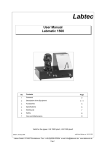
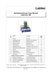
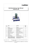
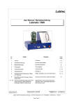
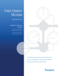
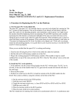
Labtec
User Manual
Labtronic 1500
Contents
No
Page
1
Foreword
2
Description of the Equipment
3
Operation Controls
5
4
Accessories
6
5
Technical data
7
6
Starting Up
8
7
Safety
9
8
Execution of the tests
10
9
Care and Maintenance
10
10
Troubleshooting
11
2
3–4
Appendices: Carrying Out the Tests
A1
Testing Masks
A2
Testing Breathing Apparatus (BA) and SCUBA
Edition: August 2006
valid from serial No: 12.05.1634
www.labtronic.de
Labtec GmbH D-74927 Eschelbronn Fax: ++49 (0)6226-970204 e-mail: [email protected] www.labtronic.de
Page 1
1
Foreword
1. 1 Important Notes
Before starting up the equipment the instructions for
use should be read carefully, and they should be observed in all matters.
The include instructions for operating and caring for a
Labtronic 1500 test stand from the serial number noted
onward. It is essential to correct operation of the
equipment that it is operated and used exclusively as
described in these instructions. Labtec accepts no responsibility for damages to persons or property or for
any late resultant squeal if the equipment has been
used in a manner that deviates from the operating instructions.
The same applies to incorrect care, maintenance and
repairs to the equipment.
Labtec recognizes no claims under the guarantee if the
equipment has been operated, maintained or repaired
by persons who have not received proper instruction
and if original replacement parts have not been used in
repair and maintenance work. The same applies if
sealed parts have been opened unless expressly permitted by Labtec.
Otherwise the sale and delivery conditions of Labtec
GmbH apply, which are in no wise extended by these
notes.
1.2
Use as Stipulated
The test stand is designed to test breathing apparatus
as per EN 137, full face masks as per EN 136 and leak
tight chemical protection suits as per EN 943-1. Contact Labtec for information on testing other breathing
equipment or chemical protection suits.
Only respiratory air as per EN 12021 (DIN 3188) is approved for operation of the equipment.
1.6
Starting up
Important !
Before the test stand is turned on care must be taken
to make sure that there is no pressure on the measuring sensors. That is to say that the high-pressure main
valve (14) must not on any account be open, a compressed air respirator must not be attached and there
must not be a face mask with activated respiratory seal
mounted on the test head. Unless all these conditions
are met the test stand will not be correctly calibrated
and the values shown in the displays will be wrong.
Once the calibration process has been completed (the
LCD displays must be on zero) the test procedures can
be started.
1.7
Operation of the test stand
Once the test stand has been started up by the Labtec
staff or appointee it can be operated by the user and
used as working equipment. It is essential for the user
to have basic knowledge of use of a PC with Windows
98, Windows NT, 200 or XP.
1.8
PC specifications
For fully automatic (computer-controlled) operation an
PC with a main memory capacity of at least 100 MB or
greater, min. clock frequency of 1000 Hz or more and
1 GB or greater of free memory on the hard disk must
be available. A suitable printer that takes DIN A4 paper is needed if printouts of protocols are to be made.
In addition, memory capacity is also needed for recording the equipment test data, how much depending
on the number and complexity of tests carried out and
the length of time data are kept on the hard disk.
1.3
Safety Hints
At the initial start-up and during work with the equipment and maintenance on it the national safety and accident prevention regulations in force are to be observed.
1.4
Transport and Setting Up
The Labtronic 1500 + 200 are fixed-position plant. It
should therefore only be transported in exceptional circumstances. The equipment is set up by a Labtec customer service team or by a specialist appointed by
Labtec.
1.5
a)
b)
Electrical Supply
Before the initial start up be absolutely
sure
that voltage and frequency are as prescribed.
The equipment must not be plugged in to a n y
power socket that does not have the
specified voltage
Labtec GmbH D-74927 Eschelbronn Fax: ++49 (0)6226-970204 e-mail: [email protected] www.labtronic.de
Page 2
2
Description of the equipment
A
C
B
M
D
L
N
-
e
J
J
H G
+
E
F
L = Audio connection socket
M = Electrical power supply with ON/OFF switch.
N = Serial interface
A = Test bench housing
B = Operation panel
C = Test head
D = High-pressure coupling / stuffing box
E = Connection Piece 300 bar
F = Pressure reducer 0...350 bar
G =MP nipple for connection of appliances
H = MP demand valve coupling
J = CSA filling coupling
+ = Test head
filling
- = Test head empty
f = Suit filling
e = Suit pressure down
2 Breathing machine ON/OFF (Switch)
Pump -10 l/min (Button)
Pump +10 l/min (Switch)
Pump –5 l/min (Button)
Pump +5 l/min (Button)
Low pressure exhausting (Button)
Medium pressure exhausting (Button
Medium pressure Bypass (Button)
High pressure valve ON/OFF (Switch)
High pressure exhauster (Button)
Labtec GmbH D-74927 Eschelbronn Fax: ++49 (0)6226-970204 e-mail: [email protected] www.labtronic.de
Page 3
2
Description of the equipment
2.1 Test Stand Housing (A)
The test stand's ergonomic design means that it can
be operated even for long periods without fatigue. It is
operated by way of electric buttons or switches and by
way of the PC keyboard and mouse when fully
automatic operation is in force. The operating board is
arranged at an angle to allow good visibility at all
times.
2.2 Operating panel (B)
Mounted on the operating panel are 3 + 1 LED
displays for high, medium and low pressure ranges + 1
for flow ranges (LQ 2000) , all with digital and bar
graph displays, together with switches and buttons for
manual operation.
2.3 Multi-function Test head (C)
The test head is a fixed-position head that can be
inflated by means of an electrical pump, so that full
face masks can be fitted with a leak proof seal
regardless of make. One measuring point is integrated
in the mouth opening of the head and one in the
forehead; each of these measures the internal
pressure inside the mask or the demand valve.
2.10 Test Connection for Chemical Suit (J)
High-speed coupling for filling leak proof chemical
protection suits.
2.11 Pressure reducer (F)
As a special model for testing the closing pressure of a
resistance alarm an additional power control valve is
mounted on the right-hand side, which allows very
slow increase of the inlet pressure from 0 to 300 bar.
2.12 Electrical Power Supply (M)
On the right-hand side of the housing there is a power
socket for machine connection with an integrated ON/
OFF switch containing a 5-A reserve safety fuse.
2.13 Serial Interface (N)
Also on the right-hand side of the housing there is a
serial interface point for data transmission to a PC.
2.14 Socket for audio connection (L)
For the connection from the microphone to the PC a
female connector for the audio is cable at the right
side.
2.4 Breathing machine
There is a breathing machine in the Labtronic 1500,
which is driven by a stepping motor and is infinitely
variable in lift and respiratory frequency. The desired
ventilation can be set in the software with the lift
frequency infinitely variable between 1 and 50/min and
volume, between 0.5 and 3.2 l.
2.5 Vacuum Pump
The integrated vacuum pump is used to generate the
airflows needed and to inflate or deflate the test head.
The desired air output (volume) can be entered in the
software at levels varying from 2 to 12 l/min.
2.6 Processor
The integrated processor takes over the control and
the signal transformation.
2.7 Air Supply (D)
For air supply (D) is present a 1 m long high
pressure pipe with an 8 mm screw connection
DIN EN ISO 8434-1. A reducer 8... 6 mm is
attached to the supply.
2.8 Connection of the Apparatus (E)
At the front side is the equipment to conclusion
connecting piece for 300 bar BA (F). For the test
of 200 bar devices a reduction adapter 300... 200
bar with relief valve is used.
2.9 Medium Pressure Connection (G, H)
On the front is a connection nipple for mediumpressure connection of appliances (G) and a highspeed coupling for the demand valve connection (H).
Labtec GmbH D-74927 Eschelbronn Fax: ++49 (0)6226-970204 e-mail: [email protected] www.labtronic.de
Page 4
3 Operation Controls
Symbol
Description
Function
Breathing machine on/off
When the switch is pressed for the first time the breathing
machine is switched on, which is recuperated by way of the
opening in the mouth of the test head. When it is pressed for
the 2nd time it is switched off
Vacuum Pump on/off
When the switch is pressed for the first time the pump pumps
off the specified volume of air through the opening in the
mouth of the test head. When it is pressed for the second
time the pump is switched off
Pressure Pump on/off
When the switch is pressed for the first time the specified volume air is pumped trough the opening in the mouth of the test
head. When it is pressed for the second time the pump is
switched off
Negative Pressure on/off
Pressing causes air to be aspirated through the opening in
the mouth of the test head so that negative pressure is generated
Positive Pressure on/off
Pressing causes air to be blown through the opening in the
mouth into the test head so that overpressure is generated
Pressure relieve on/off
Pressing causes negative pressure / over pressure in the
mask to be increased or lowered, respectively, until the pre-
Medium Pressure relive on/ Pressing causes medium pressure to be lowered (regulated)
off
until the prescribed value is achieved
Medium Pressure increase
on/off
Pressing causes the medium pressure to rise until the safety
valve on the equipment opens
High Pressure Main Valve
on/off
Pressing for the first time causes high pressure from the air
supply to be connected up to the test stand. Pressing for the
second time causes the high-pressure connection to be discontinued
High Pressure relieve on/
off
Pressing causes high pressure to be lowered until the prescribed value is reached
+
Test Head inflated
Pressing causes the test head to be
-
Test Head aspirated
Pressing causes the air to be aspirated out of the test head
f
Chemical Protection suit
filling
Pressing causes air to flow into the leak tight chemical protection suit through the chemical protection suit filling connection
e
Chemical Protection suit
exhaust
Pressing causes air to flow out of the leak tight chemical protection suit through the chemical protection suit filling connection
Labtec GmbH D-74927 Eschelbronn Fax: ++49 (0)6226-970204 e-mail: [email protected] www.labtronic.de
Page 5
4
Order-No Description
Accessories
Explanation
161 027
Dust cap RD 40
To seal breathing valve of NP full-face masks with
RD 40×1/7" (EN 148-1)
161 028
Dust cap PE 45
To seal breathing valve of HP full-face masks with
metric thread M 45×3 mm
161 032
Dust cap EAS
To seal breathing valve of HP full-face masks with
universal plug-in connector DIN 58 600
161 046
Adapter RD 40
To accept NP demand valves with RD 40×1/7" (EN
148-1) in Labtest test head
161 048
Adapter PE 45
To accept HP demand valves with metric threads M
45×3 in Labtest test head
161 051
Adapter AUSV
To accept Auer HP demand valves with plug-in connectors in Labtest test head
161 052
Adapter DRSV
To accept Dräger and B&R HP demand valves with
plug-in connectors in Labtest test head
161 059
Adapter SASV
To accept Sabre HP demand valves with plug-in
connectors in Labtest test head
161 068
Adapter ISSV
To accept Interspiro / Spiromatic P HP demand
valves with bayonet fittings in Labtest test head
161 069
Adapter EASV
To accept HP demand valves with universal plug-in
connector DIN 58 600
808 605
Silicon spray
For treatment of test head
142 507
Test head ES
As replacement (ask your Labtec agent)
161 061
161 062
CPS test adapter For testing chemical protection suits (CPS) with an
type CGA 2000
adapter set, depending on make
CPS adapter AU For CPS with Auer excess pressure valves
161 063
CPS adapter DG
For CPS with Dräger excess pressure valves (large)
161 064
CPS adapter TG
For CPS with Trelleborg excess pressure valves
161 065
CPS adapter GK
For CPS with Dräger excess pressure valves (small)
Further remarks on request
161 061
161 062 / 063
161 027, 028, 032
161 046, 048,
161 051
161 052
161 068
161 069
161 064
161 06
Labtec GmbH D-74927 Eschelbronn Fax: ++49 (0)6226-970204 e-mail: [email protected] www.labtronic.de
Page 6
5
Technical data
Part
Description
Unit
Item
Breathing Machine Engine
Voltage
Wattage
Current
Protection class
V / Hz
W
A
220-230 / 50
100
0,7 - 0,8
IP 44
Transformer
Voltage in
Voltage out
Current consumption
V / Hz
V / Hz
A
220 – 230 / 50
24 DC
E = 0,4, A= 2,5
Vacuum Pump
Voltage
max. Current consumption
max. Vacuum int.
V
A
mbar
24 DC
3
750
HPD-Magnetic Valve 1 x
Voltage
Pressure
max. Current consumption
V / Hz
bar
A
220 - 230 / 50
0...400
0,4
MP-Magnetic Valve 2x
Voltage
Pressure
Current
V / Hz
bar
W
220 - 230 / 50
0...16
13,5 x 2 = 27
LP-Magnetic Valve 9x
Voltage
Pressure
Current
V
bar
W
24 DC
0...30
10 x 9 = 90
LP-Magnetic Valve 1x
Voltage
Pressure
Current
V
bar
W
220 – 230 / 50
0...30
10 x 9 = 90
HP Sensor
Measuring range
Signal
Zero signal offset
Linearity
Hysteresis
bar
mA
FS
FS
FS
0...400
4...20
<±1%
< ± 0,5 %
< ± 0,05 %
MP Sensor
Measuring range
Signal
Linearity
bar
mA
FS
0...25
4...20
< ± 0,5 %
Flow Sensor
Voltage
Current
V
mA
24 DC
4...20
Total Unit
max. Working Pressure
bar
330
Power
V / Hz
220 / 60 V AC
24 V DC
Central Fuse
A
5
Total wattage
W
ca. 500
Dimensions (W X D x H)
mm
740 x 550 x 540
Labtec GmbH D-74927 Eschelbronn Fax: ++49 (0)6226-970204 e-mail: [email protected] www.labtronic.de
Page 7
6
Starting up
6.1 Setting Up
The test stand must be set up on a horizontal firm surface. A table or workbench at desk height (ca. 72
± cm) is advisable. It is essential that the base be free
of any vibrations. Drawers, pigeon holes or similar are
not recommended with the "plus" models, as when
breathing apparatus is connected up these are no
longer accessible.
To the left of the test stand on the workbench there
must be enough space (approx. 1 m) for putting down
masks and other test pieces. The PC and the screen,
and also the printer and the mouse pad should be positioned to the right of the test stand.
6.2 Compressed Air Connection
The test stand is best operated when connected to a
central compressed air supply by way of stock cylinders (types 1500 plus 1 and plus 2). On the right of
the test stand there is a 6-mm stuffing box. A sintered
filter with a non return valve must first be mounted on
this. This belongs to the delivery. The central air supply is then connected with the high-pressure hose also
supplied with the plant. For type LQ 1500 the air is
best supplied by way of a 6- or 6.8-l / 300-bar respiratory air cylinder.
To make execution of the high-pressure tests, an adequate high-pressure cushion of at least 300 bar must
be guaranteed.
Labtronic NT program it is then possible to work with
the test stand.
"See separate operating instructions on Labtronic
NT"
In the case of the Labtronic 1500, operation without a
PC is also possible. For this the operating elements
have to be manipulated by hand and values on the
LCD displays read and evaluated.
Caution !
Particularities of manual operation
The breathing machine
has 2 expiratory
(overpressure) valves that open automatically. During
fully automatic operation these are automatically activated when the lung is switched on. This means that
air inspired through the demand valve connected to the
test head can escape.
If the Breathing machine is operated manually, an
opportunity for breathing out between test head
and demand valve must be created. This can be
done by using an appropriate full face mask or the
additional adapter supplied routinely (adapter AVN
for normal-pressure demand valves, adapter AVP
for overpressure demand valves, with M 45 ×3 connecting thread).
6.3 Electrical connection
Simply use the connecting line supplied with the test
stand to connect it up to a 220 V / 50 Hz power source.
The test stand appliance power socket has a central 5
A safety fuse, which protects the test stand against extreme power fluctuations.
In any case we recommend a separate electric circuit
for the test stand and PC.
6.4 Turning on the Test Stand
The test stand is activated by pressing the electrical
main switch (M).
Once the test stand is switched on the sensors are
calibrated separately. The tests cannot be started until
the calibration process is complete (all LED displays
on the operating panel must be on 0).
If the test stand is separated from the PC (switched
off), in some circumstances the Labtronic NT system
program may need to be rebooted so that data synchronization can be done.
6.5 Installation of the Labtronic NT Software
The test stand cannot be operated by way of a PC until
the Labtronic NT program supplied with it has been installed. As a rule it is installed on delivery by the Labtec customer service personnel.
If you are installing it yourself, insert the CD in the CD
drive and start the set up routine by Program ® Execute. Then follow the installation instructions.
After switching on the test stand and calling up the
Labtec GmbH D-74927 Eschelbronn Fax: ++49 (0)6226-970204 e-mail: [email protected] www.labtronic.de
Page 8
7
Safety
7.1 Electrical Main Fuse
The machine power socket on the right-hand
side of the test stand has an integrated 5 A
safety fuse. This protects the test stand against
excessive power surges from external sources.
A spare fuse can be found in the socket.
7.2 Intrinsic Protection
The test stand incorporates exhaustive intrinsic
protection. If, for example, the pressure in one
pressure range rises above the defined limiting
value the system switches itself off and there is
also an acoustic alarm signal.
7.3 Self-Activating Resetting
In the case of a disturbance the system, or the
components of the system that are affected, is/
are returned to the normal settings with no intervention from the operator. Inadmissible over- or
under pressure, for example, is automatically
corrected. Following recovery of the normal condition the alarm signals stop.
7.4 Overload Protection for the Lung
The artificial lung has integrated overload protection. If the pressure exceeds the prescribed limit
values (--50...+50 mbar) the lung is switched off
automatically. It cannot be switched on again
until the pressure level is back between the prescribed limit values.
7.5 Testing of Automatic Overpressure Demand Valves
As the low-pressure range is only up to 50 mbar,
the maximum test value for the connection pressure is also only --50 mbar. For a few demand
valves the connection pressure of the automatic
overpressure can be over 50 mbar. For a tightness test or a test of the respiratory resistances
to be possible the overpressure of the demand
valve must have been switched on beforehand.
Essential caution
First switch on the (electrical power supply to
the) test stand and then call up the PC Program Labtronic NT.
Never test polluted demand valves or masks
on the test head. This would involve the danger of introducing dust particles into the
measuring system, which can have a delete-
rious effect on the function of the magnetic
valves.
Before switching off the electrical power
supply to the test stand, it is essential to
remove the breathing equipment and relieve the pressure on the test stand.
Safety systems function only when voltage is applied!
If equipment (BA, SCUBA) is attached at a device
connection connecting piece (300 bar), the free
device connection connecting piece must remain
absolutely free. Under no circumstances it may be
set with a plug.
When calibrating the test stand (after switching on)
the mouth opening must remain open, since it
comes otherwise to a wrong calibration and is
wrong the measuring data.
On the fact always it respects that the metering
hole is not clogged in the mouth opening in the
probe. Clean the opening with nil returns in low
pressure if necessary with a needle
Safety comment:
Overload of the breathing machine by MP
puncture at the Demand valve
If a Demand valve exhibits an error going by that
the medium pressure puncture, a sudden pressure surge of approx. arrives. 6... 9 bar over the
probe into the breathing machine. This has the
consequence that due to the relatively large
breathing machine bellows (Ø approx... 220 mm)
very large forces (until 14,000 N) the breathing
machine drive suddenly affect, which can entail
a damage of the breathing machine drive.
This can take place, if the Demand valve is held
from the outside in the probe during the test procedure against falling out or the breathing Demand valve were already put into the probe and
then only the hp main valve is opened.
Therefore only with the test it begins if the
HP main valve is opened and is guaranteed
that the Demand valve not suddenly and inadvertently opens and never holds during the
test procedure the Demand valve to the
probe.
Damage and damages by such an inappropriate
treatment are not covered by the guarantee.
Important for safety!
Never open the housing of the test station without disconnecting the apparatus from the electricity supply by pulling out the mains plug!
Labtec GmbH D-74927 Eschelbronn Fax: ++49 (0)6226-970204 e-mail: [email protected] www.labtronic.de
Page 9
8
Execution of the tests
Automatic test:
In the associated appendices the operations of
the test stand for (half) the automatic test are described and/or with the individual tests for the
manual enterprise. The necessary dialogues with
the system are italic ally printed.
Manual test:
With the test in the purely manual enterprise
(without computers), the measured values must
be read off from the LCD - displays of the test
stand during the measurement and calculated
and/or determined if necessary. With the operating instructions the operating requests of clicking
the switching surfaces are then allotted to the
monitor. It is advisable to note the measured values.
9
Edit test data:
Becomes in the software Labtronic NT in the
menu: test the switching surface: New test with
the right mouse button clicked, then opens a test
data window capable for editing, in which the
manually determined data can be entered (details
see manual Labtronic NT).
Fully automatic test:
With the fully automatic tests the test units and
test sequences are accomplished automatically
by the system.
Care and Maintenance
The test stand does not need any special care. It
should, however, be protected from external harmful
influences (water, damp in the form of steam, dust).
The test head needs no special maintenance, but
should be regularly cared for (end of each working day;
see below).
The test head skin is made of natural rubber (Latex).
Latex is ozone sensitive, and the test head therefore
must not be placed in full sunlight. In the case of standstill for any length of time it is best to cover it with a
cloth or something similar. If the test head becomes
dirty it should be washed with soapy water.
Do not use any solvents on it !
The skin is certainly very robust and relatively thick,
but can be damaged by sharp objects, which would
mean the test head was no longer functional. Labtec
does repairs or applies new skins in the works.
Essential caution !
There are some disinfectant agents that can damage
the latex skin of the test head if full face masks are not
rinsed 100% after disinfections and disinfectant residues therefore get onto the latex skin of the test head.
For this reason it is important to use only such disinfectant agents as are free of phosphates, aldehydes
and phenoles. No agents containing oil, grease or solvents must be used for the care of the head. These all
damage the skin of the head.
The life time of the test head is not a part of the
guarantee
Labtec GmbH D-74927 Eschelbronn Fax: ++49 (0)6226-970204 e-mail: [email protected] www.labtronic.de
Page 10
10
Troubleshooting
Fault
Possible cause
Correction
Nothing shown in LCD displays
Test stand not, or not correctly, Insert new 5 A main fuse in apconnected with mains supply via pliance power socket. Spare
mains cable
fuse is supplied in appliance
power socket
Pressure values are shown in
the LCD displays but not in the
measurement windows on the
screen
No data communication
Cable from test stand to PC is
not properly plugged in
Wrong portal selected
Select correct portal in file Labtronic32.ini. Then restart the
program
Experience suggests test results Desired values in the type file
are correct, but system displays are incorrect
values in red and message: Appliance not ready
Check values in type file and
correct as needed
No seal possible round full face
mask
As a rule this means pressure
loss at the expiration valve
Clean, moisten, change expiration valve as appropriate
Mask really has a leak
Repair mask
Negative pressure shown in dis- Temperature fluctuations in the
play rises or falls slowly and
room (windows, doors opened,
stops after a while although
sun shining in)
there is no reason to believe
there are any leaks
Take steps to ensure constant
temperature in room
Labtec GmbH D-74927 Eschelbronn Fax: ++49 (0)6226-970204 e-mail: [email protected] www.labtronic.de
Page 11