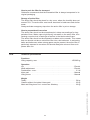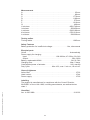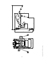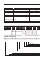
1
GB/US . . . . GLS5 Active lifter User manual - vers. 2.00 GLS5 Active lifter Item nos: 556-xxx 1.00. . . . . . . . . Manufacturer . . . . . . . . . . . . . . . . . . . . . . . . . . . . . . . . . . . . . . . . . . . . . . . . . 3 2.00. . . . . . . . . Intended use . . . . . . . . . . . . . . . . . . . . . . . . . . . . . . . . . . . . . . . . . . . . . . . . . 3 2.01. . . . . . . . . Where to use GLS5 . . . . . . . . . . . . . . . . . . . . . . . . . . . . . . . . . . . . . . . . . . . . 3 3.00. . . . . . . . . Definitions . . . . . . . . . . . . . . . . . . . . . . . . . . . . . . . . . . . . . . . . . . . . . . . . . . . 4 4.00. . . . . . . . . Use of Active lifter. . . . . . . . . . . . . . . . . . . . . . . . . . . . . . . . . . . . . . . . . . . . . 5 4.01 . . . . . . . . Warning. . . . . . . . . . . . . . . . . . . . . . . . . . . . . . . . . . . . . . . . . . . . . . . . . . . . . . 5 4.02 . . . . . . . . Safety precautions. . . . . . . . . . . . . . . . . . . . . . . . . . . . . . . . . . . . . . . . . . . . . . 6 4.03. . . . . . . . . Checklist before use . . . . . . . . . . . . . . . . . . . . . . . . . . . . . . . . . . . . . . . . . . . . 6 5.00. . . . . . . . . Operation . . . . . . . . . . . . . . . . . . . . . . . . . . . . . . . . . . . . . . . . . . . . . . . . . . . . 7 5.01 . . . . . . . . Safety functions. . . . . . . . . . . . . . . . . . . . . . . . . . . . . . . . . . . . . . . . . . . . . . . . 8 5.02 . . . . . . . . Important. . . . . . . . . . . . . . . . . . . . . . . . . . . . . . . . . . . . . . . . . . . . . . . . . . . . . 9 6.00 . . . . . . . . How to use the sling. . . . . . . . . . . . . . . . . . . . . . . . . . . . . . . . . . . . . . . . . . 10 7.00 . . . . . . . . Charging procedure. . . . . . . . . . . . . . . . . . . . . . . . . . . . . . . . . . . . . . . . . . . 14 8.00 . . . . . . . . Unpacking and preparation of the lifter . . . . . . . . . . . . . . . . . . . . . . . . . . 14 8.01 . . . . . . . . Charging and installing battery . . . . . . . . . . . . . . . . . . . . . . . . . . . . . . . . . . . 14 9.00 . . . . . . . . Troubleshooting. . . . . . . . . . . . . . . . . . . . . . . . . . . . . . . . . . . . . . . . . . . . . . 15 10.00 . . . . . . . Method of cleaning and disinfection. . . . . . . . . . . . . . . . . . . . . . . . . . . . . 16 11.00. . . . . . . . Service and lifespan . . . . . . . . . . . . . . . . . . . . . . . . . . . . . . . . . . . . . . . . . . 16 12.00 . . . . . . . Transportation and storage . . . . . . . . . . . . . . . . . . . . . . . . . . . . . . . . . . . . 17 14.00. . . . . . . . Labelling. . . . . . . . . . . . . . . . . . . . . . . . . . . . . . . . . . . . . . . . . . . . . . . . . . . . 22 15.00 . . . . . . . EC-Declaration of conformity. . . . . . . . . . . . . . . . . . . . . . . . . . . . . . . . . . . 24 16.00. . . . . . . . Environmental policy statement - V. Guldmann A/S . . . . . . . . . . . . . . . . 25 . . . . . . . . . . . . . USA and countries outside the EU . . . . . . . . . . . . . . . . . . . . . . . . . . . . . . 26 A.. . . . . . . . . . . Users guide. . . . . . . . . . . . . . . . . . . . . . . . . . . . . . . . . . . . . . . . . . . . . . . . . . 26 B. . . . . . . . . . . WARRANTY. . . . . . . . . . . . . . . . . . . . . . . . . . . . . . . . . . . . . . . . . . . . . . . . . . 26 2 © Guldmann GB/US-1971/06/2013 • # 554510 13.00 . . . . . . . Technical specifications. . . . . . . . . . . . . . . . . . . . . . . . . . . . . . . . . . . . . . . 18 13.01 . . . . . . . Indicator lamps and audio signals. . . . . . . . . . . . . . . . . . . . . . . . . . . . . . . . . 21 1.00 Manufacturer V. Guldmann A/S. Graham Bells Vej 21-23A DK - 8200 Aarhus N Tlf. +45 8741 3100 Fax. +45 8741 3131 2.00 Intended use GLS5 is a mobile active lifter which is designed to assist the user from a sitting to a standing position. It can also be used to assist the user in the toileting procedure or the beginning of the rehabilitation process. The lifter is suitable for lifting or moving a person who is capable of actively participating in the process, the user must also have good communication skills. When the active lifter is used the assumption is that: • The user can balance in a sitting position, has strength in the lower and upper body and can communicate. • The lifter will be operated by a qualified person. • The active lifter is moved at a maximum speed corresponding to normal walking speed. • The Guldmann active lifter is used with Guldmann lifting slings. Guldmann cannot be held responsible for any faults or accidents that may occur due to incorrect positioning of the lifting sling, nor for inadequate attention paid by the helper. We strongly recommend assessment of the user before every lift. © Guldmann GB/US-1971/06/2013 • # 554510 2.01 Where to use GLS5 GLS5 is designed to be used in hospitals, nursing homes, institutions and private homes. It can be used indoors whenever the user needs to be lifted or moved on a level surface. • The lifter is designed so its legs can fit under beds, around chairs / wheelchairs. • The lifter can be used in wet areas however, it must not be exposed to splash water. • The lifter is designed to be used with multiple users. When moving the lifter to another user / ward / room, perform normal hygienic disinfection. 3 Definitions 7 1. Sling attachment hooks 2. Lifting boom 3. Hip support sling attachment 4. Battery 5. Electronic control box 6. Hand control 7. Emergency stop 8.Emergency lowering electrical 9.Emergency lowering 13 manual 10. Push handle 11. Calf strap 12. Knee pad 13. Power supply 14. Lifting actuator 15.Knee pad height adjustment knob 16.Knee pad length adjustment knob 18 17. Foot plate 18. Chassis leg 19. Brake/release 20. Foot bar 2 1 1 6 14 12 11 17 3 5 8 9 10 15 4 19 16 20 4 © Guldmann GB/US-1971/06/2013 • # 554510 3.00 4.00 Use of Active lifter The lifter is designed to lift from a sitting position only. It is NOT designed to lift from lying position. Before using the lifter we strongly recommend that a full risk assessment is carried out by a qualified person to ensure the user capability, the correct slings are used and the environment is suitable. Anyone using the lifter should be fully trained on its use. Before every transfer with the active lifter, we strongly recommend you carry out a quick assessment to assess the user’s capability. Quick Assessment With the user in a seated position in chair / wheelchair / edge of bed - ask the user to push down through his/her knees (feet must be placed flat on the floor) - upon inspection the helper should see the user’s quads tighten. This indicates strength to assist with the standing procedure, it also confirms communication skills. 4.01 Warning Read the user manual fully before using the lifter. • • • • • • • © Guldmann GB/US-1971/06/2013 • # 554510 • Do not exceed the max. load. Use the lifter to lift a person only. Use the lifter on an even and level surface only. When adjusting the legs of the lifter make sure that no persons stand close to the legs due to the risk of being jammed. Do not run the lifter into persons or objects. Exchange of lifting motor/actuator according to the manufacturer’s instructions. See service chapter In case of damage, do not use the lifter until authorized by qualified service staff or the Guldmann service team. Do not use the lifter in areas where it can be splashed with water. 5 4.02 Safety precautions • Risk of entrapment between the top of the lifting actuator and lifting arm. • Risk of entrapment between the legs and the chassis when adjusting the legs. Fig. 1 Checklist before use • The lifter must be off charge. • Check the lifter is lifting and lowering and the legs are opening and closing, if you hear the audio warning (a beeping sound) DO NOT USE THE LIFTER – it needs to be charged. • Check that the green light located on the control box is illuminated when the lifter is activated. • Check that the emergency stop and lowering is working. • Make sure the lifter is running freely. • Check the slings for damage or fraying. Once you have fitted the sling (see section 6.00 - How to use the sling) you are ready to lift. With the user in a seated position • If the user is in a wheelchair or commode chair the brakes must be applied. • Position the lifting boom at lowest position and introduce the lifter square onto the user. The helper should be positioned at the side of the lifter (to ensure the lifter does not run over the user’s feet). • Open the lifter’s chassis leg width adjustment to allow access around the chair. • Position the user’s feet flat onto the foot plate and adjust the knee pad - the top of the knee pad should be level with the top of the shin, two fingers below the knee joint. • OPTIONAL – if the user has a tendency to have involuntary movements you can use the calf strap to ensure the users’ feet do not come off the foot plate. If the calf strap is not in use, fasten the strap to the back of the knee pad (avoiding loose straps). 6 © Guldmann GB/US-1971/06/2013 • # 554510 4.03 Fig. 2 • Raise the lifting boom to gain tension on the sling - ENSURE THE SLING IS STILL SECURE AND ATTACHED BEFORE CONTINUING WITH THE LIFT. Communication should be maintained throughout the lifting procedure. Alternatively you have the option to attach the sling onto the lower hooks; this will facilitate an alternative lifting position and is more suitable for the shorter user. To lower the user back into a seated position push the lifter up to the chair / commode chair / toilet and position the user so the calf is parallel to the chair / commode chair / toilet. Begin to lower and ask the user to push his/her pelvis / hip backwards to ensure the correct seated position. • Release the sling straps and move the lifter away from the user. • The sling is ready for removal - see sling user guide. Working with the Active lifter • Always maintain a good working posture when applying the sling or working with the lifter. When moving a person use the push handle and walk with the lifter keeping the load as close as possible to your body. NEVER pull or twist at arm’s length, this can cause injury to the helper. 5.00 Operation To lift/lower and adjustment of chassis leg in/out © Guldmann GB/US-1971/06/2013 • # 554510 •To lift the patient press UP arrow and to lower the patient press DOWN arrow on the hand control or the control box. • On GLS5 active lifter the leg spread width adjustment of the chassis is operated via the sideways arrows on the hand control or the control panel on the control box. • Use max. width setting when lifting to/from wide chairs, or as necessary when lifting to/ from bed, toilet and chair. • The hand control is designed to be parked at the lifting boom. • When maneuvering the lifter the chassis legs must be in the closed narrow position. 7 Safety functions Only use the emergency stop button and emergency lowering functions in emergencies. If it has been necessary to apply the emergency/safety functions due to an error on the lifter, the supplier must be contacted prior to using the lifter again. Activating the emergency stop function Should the lifter not respond to the functions selected on the hand control when it is in motion, press emergency stop. When the emergency stop function is applied, the lifter ceases to function. Switch the lifter on again by turning the emergency stop button in the direction of the arrow until it jumps out. Activating the emergency lowering function If the lifter fails to lower, activate the following: 1. Press the emergency lowering button on the control box display If the lifting boom does not lower 2. Turn the red knob in the direction of the arrow Use of brakes The rear castors are fitted with brakes. Apply the brake by stepping on the lower kick pedel. To release the brake, kick the top part of the kick pedal. Only apply the brakes if the user is pushing the lifter away with his/her feet on the foot plate while the user is seated in the chair, wheelchair, toilet or commode. 8 © Guldmann GB/US-1971/06/2013 • # 554510 5.01 Use of foot bar The foot bar is there to assist the helper to initiate movement, and to facilitate the clearing of door thresholds or to assist loading into vehicles. This is achieved by placing one foot onto the foot bar and gently pulling back on the push handle. Adjustment of knee pad The knee pad can be adjusted in vertical and horizontal direction to fit the different users. Vertical: Adjust by unscrew the yellow knob, lift or lower the knee pad in right position and then tighten the knob. Horizontal: Loosen the yellow knob, then slide the knee pad in or out until it fits the user. Then tighten the knob clockwise to lock the knee pad safely. © Guldmann GB/US-1971/06/2013 • # 554510 5.02 Important • Read the user manual and familiarize yourself with the controls and safety features on the lifter. • Always plan your lift before commencing. • Only use slings that are designed to be used with the active lifter. • Never use slings that are damaged, frayed or have unreadable labels. • Check to make sure the user does not exceed the safe working load of the lifter. • For safety reasons we DO NOT recommend transporting users through standard door frames. • Caution must be exercised when mounting the sling lifting straps onto the lifting hooks of the boom. 9 6.00 How to use the sling Standing Sling NOTE: Label must be facing away from the user and must not be turned upside down. 1. Place the sling on the user’s shoulders and / or the chair’s backrest. Ask the user to lean forward and let the sling go behind the user’s back positioning the sling two fingers beneath the shoulder blade and above the belt line. 2. Position the upper edge of the sling under the armpits and stand in front of the user. Ensure that a minimum distance of two fingers is between the sling and the armpits. Ensure the belt is securely tightened and the Velcro is functional. 3. Wrap and attach the support belt firmly around the upper body to prevent the sling from sliding. The sling is now ready for attachment to the lifter. 4. Introduce the lifter. CAUTION must be exercised to the foot plate when near user’s feet. OPTIONAL – if the user has a tendency to have involuntary movements you can use the calf strap to ensure the user’s feet do not come off the foot plate. If the calf strap is not in use fasten the strap to the back of the knee pad (avoiding loose straps). 10 © Guldmann GB/US-1971/06/2013 • # 554510 Place the user’s feet onto the foot plate and adjust the knee pad - the top of the knee pad should be level with the top of the shin on a distance of two fingers below the knee joint. 5. Raise the lifting boom to gain tension on the sling - ENSURE THAT THE SLING IS STILL SECURE AND ATTACHED BEFORE CONTINUING WITH THE LIFT. Communication with the user should be maintained throughout the lifting procedure. Alternatively you have the option to attach the sling onto the lower hooks; this will facilitate an alternative lifting position and is more suitable for the shorter user. When placing the user back into a seated position push the lifter up to the chair / commode chair / toilet and position the user so the user’s calf is parallel to the chair / commode chair / toilet. Begin to lower and ask the user to push his/her pelvis backwards to ensure the correct seated position. To remove the sling carry out the fitting instructions in reverse order, taking care to remove the sling from the user avoiding skin friction and movement. Hip Support Sling © Guldmann GB/US-1971/06/2013 • # 554510 Attachment of the hip support straps The support straps are looped at one end and have a buckle at the other. Thread the looped end through the gate on the boom and attach over the push handle bar as seen in the figure below. The strap is ready for use. 11 Hip Support Sling with the Standing Sling NOTE: Label must be facing away from the user 1. Before fitting the standing sling ask the user to lean forward and introduce the hip support sling. This should be positioned at the base of the spine either side of the hips. Fit the standing sling as previously described. 2. Introduce the lifter. CAUTION must be exer cised to the foot plate when near user’s feet. Place the user’s feet onto the foot plate and adjust the knee pad - the top of the knee pad should be level with the top of the shin two fingers below the knee joint. OPTIONAL – if the user has a tendency to have involuntary movements you can use the calf strap to ensure the user’s feet do not come off the foot plate. If the calf strap is not in use fasten the strap to the back of the knee pad (avoiding loose straps). Attach the hip support sling to the straps snapping the buckle together. Raise the lifting boom to gain tension on both slings – ENSURE THAT THE SLING IS SECURE AND ATTACHED BEFORE CONTINUING WITH THE LIFT. Adjust the hip support straps through the buckle and continue. The hip support sling should tension before the standing sling, - if it does not, then lower the user and readjust one or both slings. 12 © Guldmann GB/US-1971/06/2013 • # 554510 3. 4. As the lift progresses at approximately 60% into the standing procedure the hip support sling will loosen and once in standing the sling will be redundant allowing access to lower garments. Communication should be maintained throughout the lifting procedure. Alternatively you have the option to attach the standing sling onto the lower hooks, this will facilitate an alternative lifting position and is more suitable for the shorter user. When placing the user back into a seated position push the lifter up to the chair /commode chair/toilet and position the user so his/her calf is parallel to the chair /commode chair/toilet. 5. Begin to lower and at approximately 40% into the lowering procedure re-apply the hip support sling and continue to lower. The sling will ensure correct seated position. To remove the sling carry out the fitting instructions in reverse order, taking care to peel the sling away from the user avoiding skin friction and movement. © Guldmann GB/US-1971/06/2013 • # 554510 Alternatively: The Active Micro Plus sling can be used with the active lifter – for instructions see separate user guide for Active Micro Plus Sling. 13 7.00 Charging procedure Recharge lifter every night or when it is not in use. This maintains the batteries and ensures a long life span. Only use power supply provided by Guldmann. Recharging Recharge by plugging the power supply lead into the wall socket Recharging must be carried out when the yellow, or red LED is illuminated When the yellow LED illuminates there are approx. 10 lifts remaining When the red LED illuminates and the audio warning sounds, it is only possible to lower the patient • The power supply will turn off automatically when lifter is fully recharged • Recharging must not take place in wet rooms/bathrooms • Max. recharging time is approx. 5 hours. • • • • Alternative charging procedure Remove the battery and place it on a dry surface. Connect power supply plug to mains. Now insert the male connector into battery. 8.00 Unpacking and preparation of the lifter 8.01 Charging and installing battery Before use, the battery needs to be fully charged. See charging procedure. Unpack the battery from its packaging and locate into battery compartment by opening the lid and sliding it into position. 14 © Guldmann GB/US-1971/06/2013 • # 554510 Visual check of lifter If the packaging is damaged on receipt, each part of the lifter must be carefully examined for visible defects or deficiencies. In case of suspected damage, do not use the lifter until authorized by qualified service staff or the Guldmann Service Team. 9.00 Troubleshooting Error: Lifter does not react to input from the buttons on the hand control. 1. Does the green or yellow LED illuminate on the lifter when the control buttons on the hand control are activated? Yes see point 6. No no light visible – see point 2. No only red light visible – see point 3. Noyellow service light visible or audible “Beep”– see “indicator and audio signals matrix” point 13.01. 2. Is the battery installed in the lifter? Yes see point 4. No install a fully charged battery. 3. Is a battery with sufficient charge installed in the lifter? No install a fully charged battery. 4. Is the emergency stop activated? Yesturn emergency stop in the direction of the arrow to allow it to release and press any button on the hand control. No see point 5 5. Is the connector for the hand control fitted in the lifter, and is the lifter reacting to the buttons located on the control box? Yes replace hand control No fit connector 6. Are the connectors for the lifting motor and/or leg adjustment motor fitted? © Guldmann GB/US-1971/06/2013 • # 554510 Yes see point 5 No fit connector Contact the Guldmann Service Team if the fault cannot be found and corrected. 15 10.00 Method of cleaning and disinfection Cleaning We recommend that any parts of the active lifter that users/helper may come in contact with are cleaned with Novadan Des Wipes, Novadan Desinfect O or similar disinfection product. Desinfect O: A broad-spectrum disinfectant system as tablets. Suitable for disinfection of equipment, tools and surfaces in the healthcare sector. Novadan Des Wipes: Use a disposable wipe for cleaning and disinfection of all types of surfaces, machines and instruments in the healthcare sector. NB: Do never clean the lifter with strong acid, base or alcohol. Never clean the lifter in an autoclave machine. For easier cleaning of the foot plate it can be lifted off. The grey inserted plate can be removed separately for cleaning. Footplate and grey insert plate can be cleaned using hot water and disinfecting soap. Service and lifespan According to the international standard EN/ISO 10535 “Lifter for the transfer of disabled persons - Requirements and test methods” a safety inspection of the lifter must be performed at least once a year. The lifter has an expected lifespan of 15 years. The lifespan is estimated on the basis of correct use, cleaning and maintenance, plus annual service and maintenance carried out by qualified service engineers of the Guldmann Service Team. At the end of the expected lifespan, the lifter must then be assessed by qualified service staff as to the lifters future use. The lifespan of the lifting actuator is determined by how regular the lifter is used. 16 © Guldmann GB/US-1971/06/2013 • # 554510 11.00 Guldmann active lifter has intelligent monitoring of the usage pattern. The control box monitors the numbers of lifts and duration of the lifts. The service light on the control panel will then indicate when the lifting actuator needs replacing. This means that the lifespan of the actuator is dependent on the usage pattern of the lifter. The lifespan of the lifting actuator - examples Lifts/day User weight – 85 kg/187 lbs. User weight – 120 kg/243 lbs. Lifespan lifting actuator Lifespan lifting actuator 5 17 years 15 years 20 4.5 years 4 years The lifter is controlled by a microprocessor PC board which can be damaged if it is being touched without the necessary precautions. Therefore the electronics must only be serviced by qualified Guldmann Team. Spare parts lists and drawings are available from manufacturer or supplier. 12.00 Transportation and storage The lifter can be dismantled for transport and storage. 1. Remove the electrical cable to the base from the control box. © Guldmann GB/US-1971/06/2013 • # 554510 2. Loosen the knob and lift the mast from the base. 17 How to pack the lifter for transport Guldmann recommends that the dismantled lifter is always transported in its original packaging. Storage of active lifter The active lifter should be stored in a dry room, where the humidity does not exceed 70%. The active lifter must never be stored in bathrooms and similar areas. Always activate emergency stop when the active lifter is put on storage. How to prevent/avoid corrosion The active lifter should not be stored/remain in damp surroundings for long periods of time. Water vapor might liquefy into water on the active lifter, thus causing corrosion/rust in bearings as well as in the tubular steel frame. The active lifter should not be exposed to sudden cold or warmth. This means that one should not take a cold active lifter into a hot bathroom. In swimming baths and bathrooms where strong gases may be present, the active lifter is particularly exposed to corrosion and should always be removed from such places after use. Technical specifications Functions Lifting capacity, max: . . . . . . . . . . . . . . . . . . . . . . . . . . . . . . . . . . . 155/205 kg Operation Lift: . . . . . . . . . . . . . . . . . . . . . . . . . . . . . . . . . . . . . . . . . . . . . . . . . . . . Electric Width adjustment: . . . . . . . . . . . . . . . . . . . . . . . . . . . . . . . . . . . . . . . . . Electric Pushbuttons - max.: . . . . . . . . . . . . . . . . . . . . . . . . . . . . . . . . . . . . . . . . . 3.3 N Knee pad: . . . . . . . . . . . . . . . . . . . . . . . . . . . . . . . . . . . . . . . . . . . . . . . Manual Lifting boom: . . . . . . . . . . . . . . . . . . . . . . . . . . . . . . . . . . . . . . . . . . . . . Manual Weight Totally: . . . . . . . . . . . . . . . . . . . . . . . . . . . . . . . . . . . . . . . . . . . . . . . . . . . . 56 kg Chassis without foot plate & knee pad: . . . . . . . . . . . . . . . . . . . . . . . . . . 23 kg Mast and lifting boom incl. control box & battery: . . . . . . . . . . . . . . . . . . 22 kg 18 © Guldmann GB/US-1971/06/2013 • # 554510 13.00 Measurements A: . . . . . . . . . . . . . . . . . . . . . . . . . . . . . . . . . . . . . . . . . . . . . . . . . . . . . . 25 B: . . . . . . . . . . . . . . . . . . . . . . . . . . . . . . . . . . . . . . . . . . . . . . . . . . . . . . 90 C: . . . . . . . . . . . . . . . . . . . . . . . . . . . . . . . . . . . . . . . . . . . . . . . . . . . . 1770 D: . . . . . . . . . . . . . . . . . . . . . . . . . . . . . . . . . . . . . . . . . . . . . . . . . . . . 1190 E: . . . . . . . . . . . . . . . . . . . . . . . . . . . . . . . . . . . . . . . . . . . . . . . . . . . . . 575 F: . . . . . . . . . . . . . . . . . . . . . . . . . . . . . . . . . . . . . . . . . . . . . . . . . . . . . 1210 G: . . . . . . . . . . . . . . . . . . . . . . . . . . . . . . . . . . . . . . . . . . . . . . . . . . . . . 460 H min/max: . . . . . . . . . . . . . . . . . . . . . . . . . . . . . . . . . . . . . . . . . 850/1740 I min/max: . . . . . . . . . . . . . . . . . . . . . . . . . . . . . . . . . . . . . . . . . . . 350/450 J min/max: . . . . . . . . . . . . . . . . . . . . . . . . . . . . . . . . . . . . . . . . . 560/1190 K min/max: . . . . . . . . . . . . . . . . . . . . . . . . . . . . . . . . . . . . . . . . . 670/1310 L min/max: . . . . . . . . . . . . . . . . . . . . . . . . . . . . . . . . . . . . . . . . . . 230/320 mm mm mm mm mm mm mm mm mm mm mm mm Turning radius Turning radius : . . . . . . . . . . . . . . . . . . . . . . . . . . . . . . . . . . . . . . . . . . 1295 mm Safety Features Battery protection for insufficient voltage: . . . . . . . . . . . . . . . Yes, disconnects Electrical parts On/off: . . . . . . . . . . . . . . . . . . . . . . . . . . . . . . . . . . . . . . . . . . . . . . Automatically Power supply for charging Input: . . . . . . . . . . . . . . . . . . . . . . . . . . . . . . 100-240Vac, 47-63Hz, 0.6-0.4A Output: . . . . . . . . . . . . . . . . . . . . . . . . . . . . . . . . . . . . . . . . . . . . . . 36V, 0.83A Battery, replaceable NiMH: . . . . . . . . . . . . . . . . . . . . . . . . . . . . . . . 24V /4.5 Ah Charging time: . . . . . . . . . . . . . . . . . . . . . . . . . . . . . . . . . . . . . . . Max. 5 hours Consumption/power of actuator: . . . . . . . . . . . . . . . . . . . . . . . . . . 24V, max 8A Duty Cycle: . . . . . . . . . . . . . . . . . . . . . . . Max 10%, max. 2 min on, 18 min off. Class of tightness Active lifter: . . . . . . . . . . . . . . . . . . . . . . . . . . . . . . . . . . . . . . . . . . . . . . . . IP 32 Hand control: . . . . . . . . . . . . . . . . . . . . . . . . . . . . . . . . . . . . . . . . . . . . . . IP 44 Power supply: . . . . . . . . . . . . . . . . . . . . . . . . . . . . . . . . . . . . . . . . . . . . . . IP 20 © Guldmann GB/US-1971/06/2013 • # 554510 Labelling The product is manufactured in compliance with the Council Directive 93/42/EEC of June 14th 1993, including amendments, as medical device class 1. Classified Acc. to ISO 9999: . . . . . . . . . . . . . . . . . . . . . . . . . . . . . . . . . . . . . . . . 12 36 03 19 A B 115 20 K J G 700 H A © Guldmann GB/US-1971/06/2013 • # 554510 I I H D C E L B 1 F 180 13.01 Indicator lamps and audio signals Status Indicator lamps Audio signals Possible GLS signals Up Down Leg spread Emergency down Off-stand by Off All OK Green x x x x Low battery Yellow x x x x Critically low Battery Red Fault on lifter Yellow Beeps at button activation x x Over load x Beeps at button activation Lifetime actuator will exceed in 1.000 lifts Yellow Lifetime actuator exceeded Yellow flashes Beeps at button activation x x x x x x x x x x x x GLS5 active lifter, configurations Guldmann Product lifter type line Load in Castors Actuator Additional type type functions Scale module CLM module Service module User kg GLS5 xxx x x x x x x x 155 5 6 205 5 6 155 5 6 1 205 5 6 1 GLS5 GLS5 (x) interface Example: GLS5 205 560 000 GLS5 GLS5 205 205 5 5 6 6 0 0 0 0 0 0 0 0 0 0 Hand control © Guldmann GB/US-1971/06/2013 • # 554510 N/A N/A N/A N/A Manual emergency down, motor turned 90° Castor size ø75/ø125 mm Safe Working Load SWL: 205 kg N/A Lifter, type GLS5 21 Labelling Pictograms/labels used on product and user manual Read instructions before use CE-marking Type B in accordance with EN 60601-1 Activating the emergency lowering function Activating the emergency stop function Battery condition and charging Must not be disposed of as standard household waste, but must be recycled. Lifting boom vertical up and down movement Leg spread movement Emergency stop button Emergency lowering manually 22 © Guldmann GB/US-1971/06/2013 • # 554510 14.00 © Guldmann GB/US-1971/06/2013 • # 554510 User guide on control box S T OP 23 Examples of labels Serial number labels GLS5 (xxxx) xxx xxx xxxx GLS5 (xxxx) xxx xxx xxxx max 205 kg / 450 lbs max 205 kg / 450 lbs Part no. Prod. date Serial no. IP32 IP44 Duty Cycle xxxxxx yyyy-mm-dd xxxxx Lifter Handcontrol max: 10% 2 min/18 min www.guldmann.com Barcode 128C www.guldmann.com Power supply Hand control Part no. xxxx x x Edition xxx Date xxxx- x x- x x IP44 EC-Declaration of conformity The product is manufactured in compliance with the Council Directive 93/42/EEC of June 14th 1993, including amendments, as medical device class 1. 24 © Guldmann GB/US-1971/06/2013 • # 554510 15.00 16.00 Environmental policy statement - V. Guldmann A/S Guldmann is continuously working towards ensuring that the company’s impact on the environment, locally and globally, is reduced to a minimum. It is Guldmann’s goal to: • Comply with the current environmental legislation (e.g. WEEE and REACH directives) • Ensure that we, at the widest possible range, use RoHS compliant materials and components • Ensure that our products do not have an unnecessary negative impact on the environment regarding use, recirculation or disposal • Ensure that our products contribute to a positive working environment in the places they are utilised © Guldmann GB/US-1971/06/2013 • # 554510 Inspections are made annually by the Department for Nature and Environment from the Municipality of Aarhus using the Danish Environmental Protection Act, section 42 as a reference. 25 USA and countries outside the EU A. Users guide Before using the product, read the entire operation manual including warranty. B. WARRANTY Guldmann warrants its equipment is free from material defects under normal use, and will perform substantially in accordance with the specifications set forth in documentation provided with the equipment. This express warranty shall be in effect for one year from the date of original purchase and installation (the “Warranty Period”). If a valid claim is made during the Warranty Period for malfunction or equipment defect, Guldmann will repair or replace the equipment at no additional cost to you. Guldmann retains sole discretion as to whether the equipment will be repaired or replaced. This warranty shall be null and void if the equipment is operated and maintained in any manner inconsistent with its intended use or the instructions provided with the product. Further, in order for the warranty to remain in effect for the full Warranty Period, all service to the equipment must be provided by a Guldmann designated technician. Any parts or components repaired or replaced by a Guldmann designated technician will be guaranteed for the remainder of the Warranty Period. The warranty does not cover any part of the equipment which has been subject to damage or abuse by the user or others. The warranty does not cover any part of the equipment which has been altered or changed in any way by the user or others. Guldmann does not warrant that the lifting device functions will meet your requirements, be uninterrupted or error free. Service or Repair Contact Guldmann Repair for an authorization to return any defective item during the Warranty Period. You will be provided with a return authorization number and address for returning the item for warranty service or replacement. Do not return items to Guldmann under warranty without receiving a Return Authorization Number. If mailing the item, pack it carefully in a sturdy carton to prevent damage. Include your Return Authorization Number, a brief description of the problem and your return address and phone number. Guldmann does not assume the risk of loss or damage while in transit, so it is recommended you insure the package. 26 © Guldmann GB/US-1971/06/2013 • # 554510 The warranty set forth is in lieu of all other express and implied warranties, whether oral, written or implied, and the remedies set forth above are your sole and exclusive remedies. Only an authorized officer of Guldmann may make modifications to this warranty, or additional warranties binding on Guldmann. Accordingly, additional statements such as advertising or presentations, whether oral or written, do not constitute warranties by Guldmann. © Guldmann GB/US-1971/06/2013 • # 554510 27 © Guldmann GB/US-1971/06/2013 • # 554510 V. Guldmann A/S Corporate Office: Graham Bells Vej 21-23A DK-8200 Aarhus N Tlf. +45 8741 3100 Fax +45 8741 3131 [email protected] www.guldmann.dk Guldmann Inc. 14401 McCormick Drive, Unit A Tampa, FL 33626 Tel. 800 664 8834 Tel. 813 880 0619 Fax 813 880 9558 [email protected] www.guldmann.net