1
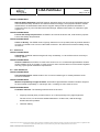
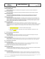
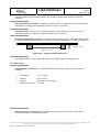
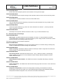
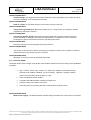
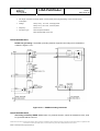
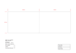
. .~-
~~~~~~
~
S2.ASU.RS.5038
, . .-
LlSA Pathfinder
tssue 2
~~~
Page 1 of 30
EGSE Overall Requirements Specification
CI CODE: 124 4200
UK EXPORT CONTROL RATING : Not Listed
Rated By : D. Head
Preparedby:
S.J. Amos
Checked by:
D. H-e
”a
,-d,
Approved by:
N. Donbar/G. Adams
Authorised by:
k
. R
.
Date:
!l&..Li
.........
[E.!....
I..-;
M. Backler
0
EADS Astrium Limited 2005
EADS Astrium Lid owns the copyright of this document which is supplied in confidence and which shall not be used for
any purpose other than that for which it is supplied and shall not in whole or in part be reproduced, copied, or
communicated to any person without written permissionfrom the owner.
EADS Astrium Limited, Registered in England and Wales No. 2449259
Registered Office: Gunnels Wood Road, Stevenage, Hertfordshire,SGl 2AS, England
Document Autogenerated from Do(
llcdule :iL
EGSE Ovetall Requirements SMcation.doc
hRnderiLeve1E G L
!equiremenls SpeciRcation
LISA Pathfinder
S2.ASU.RS.5038
Issue 2
Page 2 of 30
INTENTIONALLY BLANK
EADS Astrium Ltd owns the copyright of this document which is supplied in confidence and which shall not be used for any purpose other than that for which it is supplied and shall
not in whole or in part be reproduced, copied, or communicated to any person without written permission from the owner.
EGSE Overall Requirements Specification.doc
LISA Pathfinder
S2.ASU.RS.5038
Issue 2
Page 3 of 30
CONTENTS
1. INTRODUCTION ...........................................................................................................................................5
1.1 Scope .....................................................................................................................................................5
1.2 Applicability.............................................................................................................................................5
1.3 Requirements Identification....................................................................................................................5
1.4 Terms and Definitions ............................................................................................................................6
1.5 References .............................................................................................................................................7
1.5.1 Applicable Documents .................................................................................................................7
1.5.2 Reference Documents .................................................................................................................7
1.5.3 Standards .....................................................................................................................................7
2. ASSUMPTIONS ON INSTRUMENT EGSE CONCEPT................................................................................8
3. INSTRUMENT EGSE REQUIREMENTS......................................................................................................9
4. FEE REQUIREMENTS................................................................................................................................10
4.1 Function Requirements ........................................................................................................................10
4.1.1 Command and Control ...............................................................................................................10
4.1.2 Requirements for Communication with Core EGSE ..................................................................11
4.1.3 Log Files Management...............................................................................................................13
4.1.4 HK TM Archive Files Management ............................................................................................14
4.2 Interface Requirements ........................................................................................................................15
5. IMPLEMENTATION REQUIREMENTS ......................................................................................................16
5.1 General .................................................................................................................................................16
5.2 Lifetime .................................................................................................................................................16
5.3 Safety ...................................................................................................................................................16
5.4 Cleanliness ...........................................................................................................................................17
5.5 Parts & Materials ..................................................................................................................................17
5.6 Maintainability & Reliability...................................................................................................................18
5.7 Interchangeability & Replaceability ......................................................................................................18
5.8 Transportation & Container ..................................................................................................................18
5.9 Environment .........................................................................................................................................19
5.10 Ergonomy ...........................................................................................................................................20
5.11 Mechanical & Thermal Design ...........................................................................................................21
5.12 Electrical & EMC.................................................................................................................................22
5.13 Software Design & Development .......................................................................................................25
5.14 Workmanship......................................................................................................................................25
5.15 Identification & Marking ......................................................................................................................26
6. VERIFICATION REQUIREMENTS .............................................................................................................28
6.1 General .................................................................................................................................................28
6.2 Test Equipment ....................................................................................................................................28
FIGURES
Figure 5.8-1: Container Forklift Dimensions...................................................................................................19
Figure 5.12-1: EGSE Grounding Schematic ..................................................................................................23
Figure 5.15-1: Harness Identification (Example) .............................................................................................27
EADS Astrium Ltd owns the copyright of this document which is supplied in confidence and which shall not be used for any purpose other than that for which it is supplied and shall
not in whole or in part be reproduced, copied, or communicated to any person without written permission from the owner.
EGSE Overall Requirements Specification.doc
LISA Pathfinder
S2.ASU.RS.5038
Issue 2
Page 4 of 30
INTENTIONALLY BLANK
EADS Astrium Ltd owns the copyright of this document which is supplied in confidence and which shall not be used for any purpose other than that for which it is supplied and shall
not in whole or in part be reproduced, copied, or communicated to any person without written permission from the owner.
EGSE Overall Requirements Specification.doc
LISA Pathfinder
S2.ASU.RS.5038
Issue 2
Page 5 of 30
1. INTRODUCTION
1.1 Scope
This document specifies the general requirements applicable to the Special Check-Out Equipment (SCOE)
and Generic Modular Front-End Equipment (GMFE) used during the various test phases of the Lisa
Pathfinder program. For simplification, the equipment (SCOE and GMFE) which is planned to be operated
by the Core EGSE is addressed as Front-End Equipment (FEE) as it is considered a 'front end' to the Core
EGSE. All equipment, including the core EGSE, is addressed as the Electrical Ground Support Equipment
(EGSE).
1.2 Applicability
This specification is conceived as a higher level applicable document to the EGSE and covers the following
items:
·
the communication to the Core EGSE
·
the hardware and software interfaces
·
the design implementation requirements
·
the verification requirements
_
The definition of the specific function and performance parameter requirements associated with the
individual EGSE elements, are expected to form part of the relevant lower level EGSE requirement
specifications. The location of this document within the Lisa PathFinder document hierarchy is detailed in
[RD-02].
1.3 Requirements Identification
Requirements within this document are shown in an italic font. Each requirement is proceeded by a
summary line that contains the following fields, delimited by "/".
·
·
·
<Doors Requirement Number>OGSE-xyz. This is a unique number, assigned consecutively
<Created From> Shows parent requirement
<Test Method> T= Test, A = Analysis, I = Inspection, R = Review of Design, D = Definition
If tables are considered part of a requirement they are referenced clearly in the text and inserted after, and
separated from, the requirement table and are managed as free text attached to the identifier requirement.
The trace to the upper level requirements (Upper Links), shall be managed using the following format:
·
AAA-NNNN where AAA is a label associated to the upper document and NNNN the requirement
identifier of this upper level.
·
Or CREATED key word if the requirement has no link with upper level
This information is only relevant for verification tracing performed by Astrium and consequently may be
ignored by any Sub-contractor.
The requirements established are mainly focussed on functional and performance requirements with the
intention that maximum use of existing/recurring equipment is possible.
EADS Astrium Ltd owns the copyright of this document which is supplied in confidence and which shall not be used for any purpose other than that for which it is supplied and shall
not in whole or in part be reproduced, copied, or communicated to any person without written permission from the owner.
EGSE Overall Requirements Specification.doc
LISA Pathfinder
S2.ASU.RS.5038
Issue 2
Page 6 of 30
1.4 Terms and Definitions
Automated Procedure
Test program (application) written by the user in a high level command language
to control the execution of a test. Contains statements to send commands to the
spacecraft and to other EGSE items and to process the telemetry and other data
coming from the S/C and other EGSE items.
(synonym: Test Sequence, Control File)
C&C Message
ASCII data structure replacing the entire source packet "Application Data Field" of
a standard TC Source Packet. These packets are used to exchange commands
and feedback data between the Core EGSE and Front End Equipments.
Feedback Data
Data from a SCOE representing either measurement data from the spacecraft or
data directly measured at a dedicated spacecraft interface.
SCOE
Set of (electronic, magnetic, optical, etc.) equipment to stimulate and/or simulate
the S/C’s interfaces like sensors and actuators and/or other units (e.g. sun,
batteries, ...)
Script
A list of procedure language commands stored in an ASCII disk file. During a Test
Session a script can be called by file name and the commands contained are
interpreted and executed sequentially (similar to DOS batch file).
Spacecraft/Mission
Database containing all definitions for all data structures for the spacecraft (TM
Data Base
and TC) and for all stimuli and feed back data structures to and from other EGSE
items. (SMDB)
Stimuli Commands
Command to a SCOE to execute a stimulation of a spacecraft interface.
Structure Identifier
Field within the "Application Data Field" of a TM/TC Source Packet identifying the
data structure provided with this packet.
TC Source Packet
Packet according to [SD-01] "ESA Packet Telecommand Standard" for
commanding the spacecraft.
Test Environment
Contains the executables of all (user-) data to conduct a test. It mainly comprises
a configuration specific sub-set of SMDB data for the spacecrafts actual as-builtconfiguration, the relevant automated procedures and synoptics.
Test Session
TM Source Packet
running a test at "Run-Time" using a dedicated Test Environment.
Packet according to [SD-02] "ESA Packet Telemetry Standard" providing
housekeeping data either from the spacecraft or from any other SCOE / Front End
Equipment / Data Acquisition & Processing Block (DAPB).
EADS Astrium Ltd owns the copyright of this document which is supplied in confidence and which shall not be used for any purpose other than that for which it is supplied and shall
not in whole or in part be reproduced, copied, or communicated to any person without written permission from the owner.
EGSE Overall Requirements Specification.doc
LISA Pathfinder
S2.ASU.RS.5038
Issue 2
Page 7 of 30
1.5 References
1.5.1 Applicable Documents
The following publications form part of this document to the extent specified herein. Unless an issue is
quoted for a document, the current issue is deemed applicable. When an issue is quoted, that issue and no
other shall be used.
[AD-01]
Core EGSE Interface Control Document
S2.ASD.tbd
[AD-02]
Lisa PathFinder Acronyms, Abbreviations & Terminology Document
S2.ASU.LI.1006
[RD-03]
Product Assurance Requirements for Sub-contractors
S2.ASU.RS.1005
Paragraphs 5.8 and 10 (plus additional paragraphs as specified herein)
1.5.2 Reference Documents
The publications listed below were used in the preparation of this document, and contain background
information relating to the subjects addressed.
[RD-01]
Lisa PathFinder Packet Utilisation Standard (LPF-PUS)
S2.SYS.ICD.2001
[RD-02]
Specification and Plans Document Tree
S2.ASU.PT.1002.
1.5.3 Standards
[SD-01]
ESA Packet Telecommand Standard
ESA PSS-04-107
[SD-02]
ESA Packet Telemetry Standard
ESA PSS-04-106
[SD-03]
Ground Systems and Operations Telemetry and Telecommand Packet Utilizatio
ECSS-E-70-41A
[SD-04]
Software – Part 1: Principles and Requirements.
ECSS-E-40
EADS Astrium Ltd owns the copyright of this document which is supplied in confidence and which shall not be used for any purpose other than that for which it is supplied and shall
not in whole or in part be reproduced, copied, or communicated to any person without written permission from the owner.
EGSE Overall Requirements Specification.doc
LISA Pathfinder
S2.ASU.RS.5038
Issue 2
Page 8 of 30
2. ASSUMPTIONS ON INSTRUMENT EGSE CONCEPT
At present, there are two instrument packages on the Lisa PathFinder spacecraft, the Disturbance
Reduction System (DRS) and the LISA Test Package (LTP).
The DRS will be under the control of NASA, and will be designed, procured, controlled and maintained by
them. It will not interface with the core EGSE or any of the FEE's.
The LTP will follow a development program similar to other platform flight equipments, having Real Time
Simulator (RTS) models and associated GMFE and SCOE's.
EADS Astrium Ltd owns the copyright of this document which is supplied in confidence and which shall not be used for any purpose other than that for which it is supplied and shall
not in whole or in part be reproduced, copied, or communicated to any person without written permission from the owner.
EGSE Overall Requirements Specification.doc
LISA Pathfinder
S2.ASU.RS.5038
Issue 2
Page 9 of 30
3. INSTRUMENT EGSE REQUIREMENTS
Any specifications and/or requirements associated with the DRS EGSE will be detailed in the EID-A.
The LTP GMFE and SCOE's will be treated as FEE's, and therefore, will be subject to the requirements
detailed in this document.
EADS Astrium Ltd owns the copyright of this document which is supplied in confidence and which shall not be used for any purpose other than that for which it is supplied and shall
not in whole or in part be reproduced, copied, or communicated to any person without written permission from the owner.
EGSE Overall Requirements Specification.doc
LISA Pathfinder
S2.ASU.RS.5038
Issue 2
Page 10 of 30
4. FEE REQUIREMENTS
The requirements outlined below relate to all FEE.
4.1 Function Requirements
4.1.1 Command and Control
OEGS-40/CREATED/T
Standard Functions: The FEE shall execute standard functions called by keywords as defined in
[AD-01], chapter tbd.
The keywords given below represent C&C messages from the Core EGSE which identify mandatory and
optional standard functions by the FEE. Functions defined by these keywords shall only be used according
to the syntax defined in [AD-01], chapter tbd.
Keyword
Remark
AD1, tbd
TRANSFER
mandatory
1
RESET
mandatory
2
RESTART
optional
3
START / STOP
optional
4
APPLY
optional
5
SET
optional
6
HALT / CONTINUE
REPORT / REPLY
mandatory
Can be replaced by HK TM
7
reporting (ref. [AD-01], tbd)
ERROR
mandatory
8
MESSAGE
mandatory
8
TEST
mandatory
Can be replaced by HK TM
9
reporting (ref. [AD-01], tbd)
GETTM
mandatory
Initiates HK TM reporting
10
Specific requirements, when utilising remote commanding by the Core EGSE, are given in the section
below.
OEGS-44/CREATED/T
Specific Functions: Specific functions executed in the FEE may be defined in addition to the
standard functions. Syntax and structure of the C&C messages calling such specific function shall be
in accordance with the C&C message definition in [AD-01], section tbd. Keywords and command
syntax shall be described in detail in the individual EGSE ICD's and user manuals.
OEGS-45/CREATED/T
Local/remote functions: All functions executed on the FEE shall be called either from the local MMI
or by remote command from the Core EGSE. A complete description of command and control
functions available on the FEE shall be defined in the individual EGSE ICD's and user manuals.
EADS Astrium Ltd owns the copyright of this document which is supplied in confidence and which shall not be used for any purpose other than that for which it is supplied and shall
not in whole or in part be reproduced, copied, or communicated to any person without written permission from the owner.
EGSE Overall Requirements Specification.doc
LISA Pathfinder
S2.ASU.RS.5038
Issue 2
Page 11 of 30
4.1.2 Requirements for Communication with Core EGSE
OEGS-48/CREATED/T
Application protocol - client & server, Ref: [AD-01], section tbd: The application protocol shall be
implemented as specified in [AD-01], section tbd, with the FEE providing server services and the Core
EGSE acting as client to all sockets established.
OEGS-49/CREATED/T
Two TCP/IP sockets: Two TCP/IP stream sockets shall be established for communication to the
Core EGSE. One socket (the receive-link) for receiving messages from the Core EGSE and
performing the corresponding handshake, if any. The other socket (the send-link) for all messages
autonomously sent by the FEE to the Core EGSE, see [AD-01], section tbd
If a command from the Core EGSE, obtained via the receive-link, requests data transmission then this
transmission shall be performed using the send-link.
OEGS-51/CREATED/T
Provide service during start-up: During startup of the application software system at the FEE the
network communication services shall be provided automatically without any manual intervention.
OEGS-52/CREATED/T
Initial status: After mains power on or after reset, the FEE shall assume a local / off-line operational
mode with the following characteristics:
·
remote operation mode inactive (i.e. socket disconnected & off-line - ref [AD-01], section tbd)
·
all stimulus from the FEE to be inactive
·
FEE with archiving facility: archive subsystem inactive
·
remote interface to Core EGSE ready to receive socket connection request
OEGS-54/CREATED/T
Accept command messages: The FEE shall accept and execute command messages (called C&C)
from the Core EGSE, embedded into command source packets as defined in [AD-01], section tbd
OEGS-55/CREATED/T
Remote command: The FEE shall accept a 'Transfer remote' C&C command from the Core EGSE,
via LAN, if the logical link was previously established by a connection request. This command shall
establish a FEE configuration as follows:
·
remote operation active (ref. [AD-01], section tbd)
·
no change to processes running at the time of switching to remote operation
·
FEE with archiving facility: archive subsystem ready for mandatory recording
EADS Astrium Ltd owns the copyright of this document which is supplied in confidence and which shall not be used for any purpose other than that for which it is supplied and shall
not in whole or in part be reproduced, copied, or communicated to any person without written permission from the owner.
EGSE Overall Requirements Specification.doc
LISA Pathfinder
S2.ASU.RS.5038
Issue 2
Page 12 of 30
OEGS-57/CREATED/T
Local command: The FEE shall accept a 'switch local' command from the FEE local console or a
'Transfer local' C&C command from the Core EGSE, via LAN. This command shall establish a FEE
configuration as follows:
·
remote operation inactive (ref. [AD-01], section tbd) / logical link is not disconnected
·
no change to processes running at the time of switching to local operation
·
the FEE shall assume an operational safe mode, not presenting any hazard to the flight hardware
·
FEE with archiving facility: archive subsystem operational mode unchanged, remote interface
to the Core EGSE ready to receive commands
OEGS-59/CREATED/T
Issue messages: The FEE shall issue status and error messages to the Core EGSE in the form of
C&C messages, as defined in [AD-01], section tbd. Keywords and message syntax shall be described
in detail in the equipment ICD and user manual.
The detailed definition of command and status messages shall be defined, based on the actual design
implementation of the FEE. As a minimum, messages related to the FEE elements served by the controller,
shall be processed in accordance with the requirements defined above.
OEGS-61/CREATED/T
EGSE internal HK TM Packet: For cyclical reporting of FEE house-keeping data to the Core EGSE,
specific EGSE Internal HK TM Source Packet(s) shall be provided by the FEE conforming to [AD-01],
section tbd. Packet Structure and parameter details shall be described in detail in the equipment ICD
and user manual, as outlined in [AD-01], section tbd - Packet Data Field.
OEGS-62/CREATED/T
Reset command: The FEE shall accept a reset command via the FEE local console or LAN while in
on-line mode and via the FEE local console when in off-line mode. The reset shall bring the complete
FEE into a default state corresponding to the initial status, including disconnection of the logical link to
the Core EGSE.
OEGS-63/CREATED/T
Operation during switch-over: Switching between local and remote operation shall be possible in
any operational mode without affecting the operational conditions.
OEGS-64/CREATED/T
Switch over communication: Upon switching from local to remote, the FEE shall communicate its
operational status to the Core EGSE.
Due to manual intervention during local operation, the Core EGSE software may find the FEE in an
operational state different to that previously commanded, when switched back to remote. The
implementation of this requirement shall avoid unnecessary error messages.
OEGS-66/CREATED/T
Self-test mode: It shall be possible to initiate a self-test mode either locally on the FEE console or
from the Core EGSE via the LAN interface, depending on the operational status.
OEGS-67/CREATED/R
The self-test may only be executed if the FEE application software is in "offline" mode i.e. no
processing with the on-board system / instrument.
EADS Astrium Ltd owns the copyright of this document which is supplied in confidence and which shall not be used for any purpose other than that for which it is supplied and shall
not in whole or in part be reproduced, copied, or communicated to any person without written permission from the owner.
EGSE Overall Requirements Specification.doc
LISA Pathfinder
S2.ASU.RS.5038
Issue 2
Page 13 of 30
OEGS-68/CREATED/T
Self-test diagnostic support: The results of the self-test shall be available at the Core EGSE and at
the local console as an OK / not OK message. Further error reporting (e.g. type of error, diagnostic
message) shall also be available to enable further investigation in the event of a self test failure (i.e.
not OK).
OEGS-69/CREATED/T
Interfaces during self-tests: Self-tests shall be possible with the FEE either connected or
disconnected to the on-board equipment.
OEGS-70/CREATED/T
Special attention shall be paid to the interfaces connecting the FEE with the on-board equipment. The
self-test shall ensure that those interfaces are in a well defined state, such that no hazard may exist to
the on-board equipment.
4.1.3 Log Files Management
OEGS-72/CREATED/T
Log file generation: During operations, in both local and remote modes, the following information
shall be recorded in ASCII log files:
·
Instructions, commands, and messages received from the Core EGSE
·
keyboard entries during local operation
·
all events, messages, errors etc. occurring during operations (sent to the Core EGSE in remote
mode)
·
operator messages to the local display generated during local mode operation
OEGS-74/CREATED/T
Log files management: The following shall be applied as a minimum.
·
Log files shall be created on the controller local disk using unambiguous file names
indicating the test by name and the creation time.
·
The size of a log file shall be limited to a reasonable file size (i.e. 500 lines). If this size is
reached the current log file shall automatically be closed and a new file shall be opened.
Log files, which are closed, shall be accessible by the operator.
·
Log files shall not be automatically deleted or overwritten.
OEGS-76/CREATED/T
Log entry time stamp: Each entry in a log file shall be preceded by a time stamp indicating the date
and time. This shall be obtained from the controller system time in the format "dd.mm.yyyy
hh:mm:ss".
EADS Astrium Ltd owns the copyright of this document which is supplied in confidence and which shall not be used for any purpose other than that for which it is supplied and shall
not in whole or in part be reproduced, copied, or communicated to any person without written permission from the owner.
EGSE Overall Requirements Specification.doc
LISA Pathfinder
S2.ASU.RS.5038
Issue 2
Page 14 of 30
OEGS-77/CREATED/T
Log Entry Visualisation: All events subject to log file entry shall be displayed on-line (i.e. at the time
of occurrence), in a synoptic window on the controller local console. Filters shall be available to allow
selection of the message types to be displayed. This shall include an 'All' message selection.
OEGS-78/CREATED/T
Log file browsing and retrieval: It shall be possible to browse through the log files directory by
means of a standard (i.e. operating system utility) file manager and to retrieve log files corresponding
to a required time and date. The contents of the selected log file shall then be available for displaying
and printing.
OEGS-79/CREATED/T
Log files remote access: The log files shall be accessible from any LAN connected computer (e.g.
the Core EGSE) via FTP.
4.1.4 HK TM Archive Files Management
OEGS-81/CREATED/T
HK TM archiving: In local operation mode, all FEE internal HK TM parameters acquired during a test
shall be recorded in a telemetry archive file in the form of binary FEE internal HK TM Source packets
as generated for transfer to the Core EGSE, see [AD2], section tbd.
During remote operations from the Core EGSE such local archiving is not required as all HK TM packets are
transferred to the Core EGSE and are subject to archiving by the Core EGSE.
OEGS-83/CREATED/T
Archive files management: The following shall be applied as a minimum.
·
Archive files shall be created on the controller local disk using unambiguous file names
indicating the test by name and the creation time.
·
The size of a archive file shall be limited to a reasonable file size (i.e. 500 entries). If this
size is reached the current archive file shall automatically be closed and new file shall be
opened. Archive files, which have been closed, shall be accessible by the operator.
·
Archive files shall not be automatically deleted or overwritten.
OEGS-85/CREATED/T
Archive entry time stamp: Each entry in an archive file shall be preceded by a time stamp indicating
date and time. This shall be obtained from the controller system time in the format "dd.mm.yyyy
hh:mm:ss".
OEGS-86/CREATED/T
Archive file browsing and retrieval: It shall be possible to browse through the archive files directory
by means of a standard (i.e. operating system utility) file manager and to retrieve archive files
corresponding to a required time and date. The contents of the selected archive file shall then be
available for displaying and printing.
EADS Astrium Ltd owns the copyright of this document which is supplied in confidence and which shall not be used for any purpose other than that for which it is supplied and shall
not in whole or in part be reproduced, copied, or communicated to any person without written permission from the owner.
EGSE Overall Requirements Specification.doc
LISA Pathfinder
S2.ASU.RS.5038
Issue 2
Page 15 of 30
For visualisation (i.e. display and print) of binary information such as archived HK TM packets commercial
off-the-shelf tools (e.g. "Hex-Editor" by the operating system; UltraEdit-32 by IDM Computer solutions, Inc.
(www.idmcomp.com) for PC running under Windows) are considered sufficient. A dedicated application is
not mandatory. Interpreting the specific data structure, such as the "TM Source Packet", is not required.
OEGS-88/CREATED/T
Archive files remote access: The archive files shall be accessible from any LAN connected
computer (e.g. the Core EGSE) via FTP.
4.2 Interface Requirements
OEGS-90/CREATED/R
Communication Interface to Core EGSE: The communication between the FEE and the Core
EGSE shall be performed by means of a Local Area Network (LAN) as per [AD-01], section tbd:
·
the physical network is referenced / named EGSE LAN
·
Ethernet according to IEEE 802.3
·
10-Base-2 thin Ethernet or 10/100-Base-T RJ45 connector twisted shielded pair
·
TCP/IP stream socket peer-to-peer connections
OEGS-93/CREATED/R
Ethernet Adapter: According to [AD-01], section tbd, an Ethernet adapter, supporting 100BaseT,
shall be provided with galvanically isolated line drivers in order to ensure no ground loops are induced
via the network cabling.
OEGS-94/CREATED/T
IP address configuration: All IP addresses and socket / port numbers shall be configurable by the
user. A step-by-step procedure describing IP address and port number settings shall be provided in
the equipment user manual.
OEGS-95/CREATED/T
EGSE Synchronisation: Time synchronisation of FEE computers shall be achieved via the EGSE
LAN by means of the UNIX standard Network Time Protocol (NTP) with the Core EGSE acting as the
time server.
EADS Astrium Ltd owns the copyright of this document which is supplied in confidence and which shall not be used for any purpose other than that for which it is supplied and shall
not in whole or in part be reproduced, copied, or communicated to any person without written permission from the owner.
EGSE Overall Requirements Specification.doc
LISA Pathfinder
S2.ASU.RS.5038
Issue 2
Page 16 of 30
5. IMPLEMENTATION REQUIREMENTS
This section provides general design, implementation, manufacturing and environmental requirements.
These requirements are applicable for the implementation, as well as for selection of commercial equipment.
Justification shall be given in the case of deviation from the guidelines below.
5.1 General
OEGS-99/CREATED/R
General design approach: The EGSE shall be based on commercially available and supported
hardware and software as far as possible.
OEGS-100/CREATED/R
Metric Standards: Design, manufacture and assembly shall be consistent with the ISO metric
standard and shall satisfy EU standards.
5.2 Lifetime
OEGS-102/CREATED/A
Continuous Operation: The EGSE shall generally be designed for continuous operation. Test
periods of up to 20 days shall be supported without the need for interruptions due to resource
limitations such as disk space or storage medium exchange or routine maintenance activities.
OEGS-103/CREATED/A
Design lifetime: The EGSE shall be designed for an operational lifetime extending at least 6 years
after acceptance.
OEGS-104/CREATED/A
Assembly Cycles: The EGSE shall be designed to withstand at least 10 cycles of packing, transport,
storage, unpacking and preparation for use.
5.3 Safety
OEGS-106/CREATED/I,R
Design safety: The EGSE design shall avoid sharp corners and edges and no material shall be used
which may constitute a risk to the health of personnel.
OEGS-107/CREATED/T
Locking brake devices: All movable equipment shall have locking brake devices.
OEGS-108/CREATED/R
Fail-safe design: The EGSE shall in no way be able to endanger the spacecraft system and / or
operating personnel. Fail-safe design shall be built in to ensure that any single point failure in the
EGSE does not propagate and cause damage to the on-board equipment.
OEGS-109/CREATED/R
Failure tolerant design: The EGSE elements shall be designed for tolerance to failures in interfacing
equipment (i.e. the onboard equipment or other EGSE elements).
OEGS-110/CREATED/A
Inclined EGSE: The EGSE shall remain stable when inclined at an angle of up to 20°.
EADS Astrium Ltd owns the copyright of this document which is supplied in confidence and which shall not be used for any purpose other than that for which it is supplied and shall
not in whole or in part be reproduced, copied, or communicated to any person without written permission from the owner.
EGSE Overall Requirements Specification.doc
LISA Pathfinder
S2.ASU.RS.5038
Issue 2
Page 17 of 30
OEGS-111/CREATED/T
National Safety Standards: All EGSE shall be designed, taking into account the applicable national
and international safety standards and shall be tested accordingly. The equipment shall be suitable
marked with a CE-identification label and the supplier shall provide the pertinent Declaration of
Conformity (DoC) as part of the End-Item Data Package. Additional information is contained in [AD03] Para. 11.
OEGS-112/CREATED/R
Launch Site Safety Requirements: All EGSE to be used at the launch site, shall meet any specific
Launch Site Safety Requirements.
OEGS-135/CREATED/R
Centre of Gravity: The EGSE centre of gravity shall be as low as possible, with any wheels attached
as close as possible to the corners of the EGSE rack base. This will ensure maximum stability during
movement.
5.4 Cleanliness
OEGS-115/CREATED/R
Cleanability: All EGSE shall be designed for easy cleanability, i.e. flat surfaces and no sensivity to
cleaning agents.
OEGS-116/CREATED/R
Surface treatment: All EGSE to be used in the clean-room or in contact with flight hardware shall be
surface treated, as far as possible, in order to meet a class 100,000 clean-room environment together
with any project specific cleanliness requirements.
5.5 Parts & Materials
OEGS-118/CREATED/R
Corrosion Resistance: Metals shall be of a corrosion-resistant type or suitably treated to resist
corrosive conditions.
OEGS-119/CREATED/R
Material compatibility to flight hardware: All EGSE to flight hardware interfaces shall be analysed
for their material compatibility i.e. electrolytic and / or fretting corrosion shall not occur.
OEGS-120/CREATED/R
Forbidden materials: The following materials shall not be used:
·
Polyvinyl Chloride (PVC) for items used on or in close proximity to any flight equipment.
The use of PVC, for other items situated elsewhere in a clean room, shall be strongly
avoided wherever possible.
·
Cadmium Plating
EADS Astrium Ltd owns the copyright of this document which is supplied in confidence and which shall not be used for any purpose other than that for which it is supplied and shall
not in whole or in part be reproduced, copied, or communicated to any person without written permission from the owner.
EGSE Overall Requirements Specification.doc
LISA Pathfinder
S2.ASU.RS.5038
Issue 2
Page 18 of 30
5.6 Maintainability & Reliability
OEGS-123/CREATED/R
Minimum Maintenance: The EGSE shall be designed for minimum scheduled maintenance.
OEGS-124/CREATED/R
Easy Accessibility: Components requiring scheduled maintenance shall be easily accessible.
OEGS-125/CREATED/R
Description of Maintenance Procedure: Components shall be identified and maintenance
procedures described within the equipment users manual dedicated maintenance chapter.
OEGS-126/CREATED/R
Manufacturing & Assembly Standards: The EGSE shall be manufactured and assembled to the
usual standards of ground based electronic instrumentation and engineering practice of spacecraft
testing. Judgment and acceptance of EGSE shall be based on the design margin applied, possible
failure modes and their effect, and soundness of the design.
OEGS-127/CREATED/R
EGSE Downtime: The EGSE shall be designed for a minimum downtime including routine
maintenance in order not to jeopardize the overall satellite AIT programme. Maximum EGSE reliability
shall be attained by a combination of the following services which shall be provided by the EGSE
suppliers
·
24 hours response service for "first aid" trouble shooting support.
·
spare parts, maintenance, and repair service which guarantees a down time of not
more than 48 hours.
5.7 Interchangeability & Replaceability
OEGS-130/CREATED/R
Interchangeability: The EGSE sub-assemblies, parts and components bearing the same part
number shall be both physically and functionally interchangeable.
OEGS-131/CREATED/R
Replaceability: Equipment design tolerances shall not be more stringent than necessary to achieve
the performance and replacement ability required throughout the operational life of the equipment.
5.8 Transportation & Container
OEGS-133/CREATED/R
Transport capability: All EGSE shall be designed for road, air (including helicopter), and ship
transportation by normal commercial facilities readily available in Europe.
Transportation of the EGSE, within Europe, will be mainly by road.
OEGS-136/CREATED/R
Containers for transport and storage: All EGSE items shall be provided with re-useable containers
to comply with the transport and storage environments given herein.
OEGS-137/CREATED/R
Container environmental protection: Containers shall be designed to protect the EGSE from the
worst case transportation environment as specified below. If the transported EGSE does not comply
EADS Astrium Ltd owns the copyright of this document which is supplied in confidence and which shall not be used for any purpose other than that for which it is supplied and shall
not in whole or in part be reproduced, copied, or communicated to any person without written permission from the owner.
EGSE Overall Requirements Specification.doc
LISA Pathfinder
S2.ASU.RS.5038
Issue 2
Page 19 of 30
with the specified environmental conditions, the containers shall provide adequate protective
measures.
OEGS-138/CREATED/R
Minimum packing preparation: The EGSE containers shall be designed such that the EGSE item
preparation for packing and the packing process are kept to a minimum.
OEGS-398/CREATED/R
Container access: Access to the containers shall be possible without the use of any tools. If
absolutely necessary, simple tools maybe acceptable e.g. screwdriver.
OEGS-139/CREATED/R
Containers with forklift provisions: The EGSE containers with a mass > 30 kg when loaded, shall
be equipped with forklift provisions (e.g. mounted on a pallet) of dimensions as given by Figure 5.8-1.
11 cm + 1cm
60 cm ± 1 cm
Figure 5.8-1: Container Forklift Dimensions
OEGS-399/CREATED/R
All packing containers shall comply with ISPM 15 as detailed in [AD-03] paragraph 3.13.
5.9 Environment
OEGS-142/CREATED/R
Transportation environment: The EGSE shall meet the following transportation environment
conditions:
·
Temperature:
-50°C to +60°C
·
Humidity:
up to 100% RH
·
Pressure:
equivalent to 15 km altitude
·
Pressure change rate: < 20 hPa/s
OEGS-144/CREATED/R
Normal operational environment: The EGSE shall be designed for operation in a laboratory
environment which is conditioned as follows:
EADS Astrium Ltd owns the copyright of this document which is supplied in confidence and which shall not be used for any purpose other than that for which it is supplied and shall
not in whole or in part be reproduced, copied, or communicated to any person without written permission from the owner.
EGSE Overall Requirements Specification.doc
LISA Pathfinder
·
Temperature:
16°C to 27°C
·
Humidity:
30% up to 60%
·
Cleanliness:
at least visibly clean
S2.ASU.RS.5038
Issue 2
Page 20 of 30
OEGS-146/CREATED/R
Launch pad environment: EGSE installed on the launch pad or the umbilical mast shall be
compliant with the following conditions:
·
Temperature:
10°C to 27°C (tbc)
·
Humidity:
up to 90% RH (condensing) (tbc)
·
Pressure
800 to 1050 mbar (tbc)
·
Acoustic Noise:
up to 138 dB for 10 sec. max. (tbc)
OEGS-148/CREATED/R
Storage environment: The EGSE shall meet the following storage environment conditions:
·
Temperature:
-40°C to +60°C
·
Humidity:
up to 85% RH
·
Pressure
800 to 1050 mbar
Where the storage environment conditions, for the EGSE, are in conflict with the build standard of
commercially available equipment, this requirement may be waived.
OEGS-151/CREATED/R
Environmental test conditions: EGSE which is required to operate in the vicinity of on-board
equipment during the environmental test programme - and as such is exposed to the same
environmental conditions as the item under test - shall be designed to withstand these conditions
without degradation of performance, and without deteriorating the represesentativity of test results.
5.10 Ergonomy
OEGS-153/CREATED/R
Equipment to be lifted by hand shall not be heavier than 25 kg.
OEGS-155/CREATED/R
The maximum force necessary to operate a control or mechanism by hand shall be 120 N.
OEGS-156/CREATED/R
The EGSE design shall provide adequate space and accessibility for the operating personnel for
nominal and non-nominal tasks.
OEGS-157/CREATED/I
It shall be possible to slide a drawer to its full forward position without disconnecting any cables.
EADS Astrium Ltd owns the copyright of this document which is supplied in confidence and which shall not be used for any purpose other than that for which it is supplied and shall
not in whole or in part be reproduced, copied, or communicated to any person without written permission from the owner.
EGSE Overall Requirements Specification.doc
LISA Pathfinder
S2.ASU.RS.5038
Issue 2
Page 21 of 30
OEGS-158/CREATED/R
Panels which need frequent operator access shall be at an ergonomic height.
OEGS-159/CREATED/R
Any adjustments that are required during normal operation shall be carried out from the front panels.
OEGS-160/CREATED/R
All permanent connections shall be on the rear of the EGSE racks.
OEGS-161/CREATED/R
The rack side walls shall be extended to protect the front panel elements from any possible crash
damage during rack movement.
OEGS-162/CREATED/R
Critical front panel switches (e.g. power ON / OFF, Remote/Local, Self-test ...) shall be protected
against inadvertent activation.
OEGS-163/CREATED/R
Red lamps on front panels shall be reserved for alarm, no-go or failure indications only.
5.11 Mechanical & Thermal Design
OEGS-165/CREATED/R
Rack layout: The EGSE shall be housed in standard '19" racks' or consoles wherever possible;
overall height shall not exceed 2m. This shall include any mains voltage isolation transformers, which
shall be mounted in the lowest possible rack portion.
This does not apply to COTS computer equipment.
OEGS-167/CREATED/R
Easy access for maintenance: The racks and drawers shall be of a modular design, allowing easy
access for maintenance, trouble shooting and replacement.
OEGS-168/CREATED/R
Drawer mounting: The drawers shall be mounted on telescopic slides or angle bars and shall have
locking handles or screw fastenings at the front.
OEGS-169/CREATED/R
Self-steering wheels: All EGSE items with a mass > 40 kg - shall be mounted on self-steering
wheels (castors) for transport over short distances within a facility. Minimum diameter for these
wheels shall be 80 mm.
OEGS-171/CREATED/R
Rack lifting by standard forklifts: The EGSE racks shall be compatible with lifting by standard
forklifts.
OEGS-172/CREATED/R
Castor lock devices: The EGSE racks shall be either firmly supported on the floor or have devices to
lock the castors.
OEGS-173/CREATED/R
Design for transportation: Provisions for transportation, handling, and maintenance shall be
incorporated in each rack and major unit. The EGSE mechanical design shall withstand repeated
transportation between integration, test, and launch sites without disassembly.
EADS Astrium Ltd owns the copyright of this document which is supplied in confidence and which shall not be used for any purpose other than that for which it is supplied and shall
not in whole or in part be reproduced, copied, or communicated to any person without written permission from the owner.
EGSE Overall Requirements Specification.doc
LISA Pathfinder
S2.ASU.RS.5038
Issue 2
Page 22 of 30
OEGS-174/CREATED/T
Thermal design: The equipment shall contain adequate cooling capabilities (air in/outlets and fans),
to avoid overheating in the operating environment.
OEGS-175/CREATED/R
Rack air outlets: Air in/outlets shall be on the bottom and top of the rack.
OEGS-176/CREATED/T
Temperature regulated Fans: Wherever possible, the on / off operation of cooling fans shall be
regulated by temperature sensors.
OEGS-177/CREATED/I
Connectors physical design: Electrical connections within the equipment shall be secured to
prevent breakage or changes in the electrical characteristics of outputs as a result of vibration,
acceleration or shocks encountered under the specified environment.
OEGS-178/CREATED/I
External connectors must be equipped with locking devices.
OEGS-179/CREATED/R
The access to all connectors shall be such that any individual connector can be mated or demated
without the need to disconnect any other connector.
OEGS-180/CREATED/R
Mismatch of connectors must be physically impossible.
5.12 Electrical & EMC
The EGSE shall include a single / three phase mains isolation transformer unit according to the capabilities
as follows:
·
high common mode noise rejection by physically separated primary/secondary
windings and separate shielding for each winding; capacitive coupling between
primary and secondary windings shall be <1pF
·
class II double/reinforced insulation
·
compliant with DIN/VDE 0551 / EN 60742 / EN 61010
·
protection earth at the output connectors
·
grounding stud for connecting the rack chassis and the protection earth
OEGS-184/CREATED/A
Mains power supply: The EGSE interface with the facility provided mains power shall be as follows:
EADS Astrium Ltd owns the copyright of this document which is supplied in confidence and which shall not be used for any purpose other than that for which it is supplied and shall
not in whole or in part be reproduced, copied, or communicated to any person without written permission from the owner.
EGSE Overall Requirements Specification.doc
LISA Pathfinder
·
S2.ASU.RS.5038
Issue 2
Page 23 of 30
One single connection via single phase or three phase power plug depending on the rack total power
consumption
·
Voltage:
230V(± 10%), 16 A max., AC single phase
400V(± 10 %), 32 A max., AC three phase
·
Frequency:
·
Connector Type:
50 Hz ± 10 %
230V European Standard
400V IEC 309 CEE 16A or 32 A
OEGS-186/CREATED/T
EGSE rack grounding: The EGSE grounding shall be supported according to the schematics
outlined in Figure 5.12-1.
Figure 5.12-1: EGSE Grounding Schematic
OEGS-188/CREATED/R
Grounding of desktop EGSE: EGSE which, for practical reasons, cannot be installed in racks, shall
be grounded with the rules as
EADS Astrium Ltd owns the copyright of this document which is supplied in confidence and which shall not be used for any purpose other than that for which it is supplied and shall
not in whole or in part be reproduced, copied, or communicated to any person without written permission from the owner.
EGSE Overall Requirements Specification.doc
LISA Pathfinder
S2.ASU.RS.5038
Issue 2
Page 24 of 30
follows:
·
from a spare mains power outlet inside the rack or
·
from a facility mains power outlet, if the design provides galvanic isolation to all other EGSE.
OEGS-190/CREATED/R
Circuit grounding: Electrical circuit ground shall be insulated from the equipment chassis ground
wherever possible. In cases where this cannot be achieved, due to technical or physical reasons (e.g.
for RF equipment), an additional separation transformer, DC-block or some other method shall be
provided to exclude ground loops involving the on-board equipment.
OEGS-191/CREATED/R
Circuit ground access: The equipment circuit ground shall be accessible at ground studs of plugs at
the equipment front or rear panel.
OEGS-192/CREATED/A,R
Harness electrical design: Signal deterioration due to resistive, inductive and capacitive behaviour
of the interconnection lines or coax cables shall be such that all relevant applicable signal
specifications are met.
OEGS-193/CREATED/T
Isolation Resistance: The isolation resistance between loads which are not connected together and
between shields and centre conductor and shield to shield shall be at least 10 MOhm at 500 VDC.
OEGS-194/CREATED/R
Shield routing: Shields shall be routed continuously through any connectors on separate pins.
OEGS-195/CREATED/R
Termination of cable shields: Termination to ground shall be at one side only to avoid ground loops.
This especially applies to any EGSE harnesses connected to the spacecraft / flight equipment, where
shields shall be connected to ground at the EGSE side and shall be unconnected at the Spacecraft side
(see Figure 5.12-1 above). Deviations from this baseline shall be subject to customer approval.
OEGS-197/CREATED/R
Hazardous voltages: The design shall ensure that personnel cannot come into contact with exposed
conducting surfaces carrying a voltage > 24 V DC or > 24 V AC peak.
OEGS-198/CREATED/R
Test points: Test points shall be provided to allow easy isolation and identification of failed items
without dismounting or disconnecting other equipment
OEGS-199/CREATED/R
Test points short circuit: Test points shall be short circuit protected, to the extent practical. The testpoints shall make use of common measurement probe types (e.g. banana jacks or BNC test points or
similar).
OEGS-200/CREATED/R
EMC Design: The EGSE shall be designed to support EMC tests. Therefore, the EGSE generated
background emissions during EMC tests shall stay at least 10 dB below the level to be verified, and
the EGSE shall be capable of withstanding the system susceptibility tests without malfunction.
This implies, that equipment which must unavoidably be present in the EMC test chamber shall meet the
same emission and susceptibility requirements as the on-board equipment, and further, the stimulus /
EADS Astrium Ltd owns the copyright of this document which is supplied in confidence and which shall not be used for any purpose other than that for which it is supplied and shall
not in whole or in part be reproduced, copied, or communicated to any person without written permission from the owner.
EGSE Overall Requirements Specification.doc
LISA Pathfinder
S2.ASU.RS.5038
Issue 2
Page 25 of 30
feedback-cabling to be used during system EMC tests shall be designed with proper shielding / twisting for a
minimum field to cable coupling.
OEGS-202/CREATED/T
Bonding resistance: Bonding of adjacent structural parts and equipment within the EGSE racks shall
be accomplished by metallic contacts providing an ohmic resistance of less than 50 mOhm.
OEGS-203/CREATED/R
Permanent open-circuit and short-circuit: All signal input/output interfaces (video, RF,…) must
support permanent open-circuit and short-circuit.
5.13 Software Design & Development
All EGSE software for use in the higher level AIV shall be of a layered structure comprising the following
three main layers:
System Software which is the fully commercial software environment chosen by the EGSE
supplier. It will typically consist of the operating system, a relational database management
system, compilers / interpreters, graphic tools, communication software, e.t.c.
Operational Software which is provided by the EGSE supplier for use during the AIT program
(e.g. data archive operation software, application software development environment,
measurement data evaluation software)
Application Software generated by the AIT team using the EGSE for particular test purposes
(control files, test sequences, synoptic display definitions, data sets for simulation purpose,
AIT data base)
The following general design requirements for operational software and application software
shall be met:
OEGS-207/CREATED/R
Operational software: The EGSE operational software shall be based on commercially available and
supported software. Development of operational software, for use during higher level AIT activities,
shall be in accordance with [SD4] the ESA software engineering standard for small projects.
OEGS-208/CREATED/R
Application software: Application software shall be developed according to the project check-out
software plan.
5.14 Workmanship
OEGS-210/CREATED/I
Workmanship: The EGSE shall be designed, fabricated and finished to a high quality of fit and finish
and for adherence to the specified requirements. Particular attention shall be given to the absence of
burrs and sharp edges which might cause injury to personnel or damage to flight or ground hardware.
Paint finishes shall be free of runs, voids, dirt, over-spray and subsurface voids or contamination.
Attention shall be paid to neatness and thoroughness of soldering and wiring.
EADS Astrium Ltd owns the copyright of this document which is supplied in confidence and which shall not be used for any purpose other than that for which it is supplied and shall
not in whole or in part be reproduced, copied, or communicated to any person without written permission from the owner.
EGSE Overall Requirements Specification.doc
LISA Pathfinder
S2.ASU.RS.5038
Issue 2
Page 26 of 30
5.15 Identification & Marking
OEGS-212/CREATED/I
EGSE identification label: The EGSE identification plates shall be visible, when installed, and their
locations shall be defined in the assembly drawings. If the label size is such that all identifiable criteria
cannot be specified, the order of precedence for identification data shall be as follows, but the part
number, serial number and configuration number are mandatory on all configuration items
·
Part number
·
Serial number
·
Configuration Item (CI) number
·
Nomenclature of the item
·
Contract number
OEGS-214/CREATED/I
Container identification label: Each container shall, in addition to the above, be marked with the
information as follows:
·
Lisa Pathfinder project
·
Item All-up-weight
·
Item CoG
·
Safe Working Load
·
Hoisting point identification
·
Special safety instructions
·
Re-usable container marking
·
content identification / nomenclature with S/N
OEGS-216/CREATED/I
Location of identification label: The identification labels of EGSE drawers shall be located such that
removal of the drawers is not necessary in order to ascertain their part number. All Printed Circuit
Boards (PCB) and other removable items shall be clearly marked with their part number. All part
numbers shall include their relevant change / revision index. Instruction plates shall be securely
fastened to enclosures instrument panels and shall be placed in positions where they can easily be
read. Precautionary markings shall be provided as necessary to warn personnel of any hazardous
conditions and precautions to be observed.
OEGS-217/CREATED/I
Harness identification: A numbering system shall be used for identification of cables, plugs and
connectors of all EGSE components. These ID numbers shall appear on all relevant diagrams,
drawings and associated parts lists and manuals. Labeling the cable itself is outlined, as an example,
by Figure 5.15-1
EADS Astrium Ltd owns the copyright of this document which is supplied in confidence and which shall not be used for any purpose other than that for which it is supplied and shall
not in whole or in part be reproduced, copied, or communicated to any person without written permission from the owner.
EGSE Overall Requirements Specification.doc
S2.ASU.RS.5038
Issue 2
Page 27 of 30
LISA Pathfinder
max 1 m
max 1 m
FPA SCOE *)
PTI: 715100
S/N: 006
P05 *)
F PA SCOE
EGSE Connector
- identifier
- connected unit
Cable
- u nit name
- PT I no.
- serial no.
FPA SCOE *)
PTI :71 5100
S/N: 006
Ca ble
- unit name
- PT I no.
- ser ial no.
P08 *)
XMM
RF C2
S/C Connector
- identifier
- S/C name
- connected S/S or Br acket
... one lable
for each connector
Ca bl e_ La bels .d sf
P02 *)
FPA SCOE
*) example
Figure 5.15-1: Harness Identification (Example)
EADS Astrium Ltd owns the copyright of this document which is supplied in confidence and which shall not be used for any purpose other than that for which it is supplied and shall
not in whole or in part be reproduced, copied, or communicated to any person without written permission from the owner.
EGSE Overall Requirements Specification.doc
LISA Pathfinder
S2.ASU.RS.5038
Issue 2
Page 28 of 30
6. VERIFICATION REQUIREMENTS
6.1 General
The Sub-contractor will be responsible for the full verification against the specified requirements and will be
subject to a formal verification close-out.
6.2 Test Equipment
Adequate test equipment and simulators shall be made available to support the EGSE equipment
verification process. This test equipment is not deliverable and may therefore be obtained from the suppliers
laboratory equipment inventory. Of particular importance is the simulation of the communication interface
with the Core EGSE and the simulation of the interfaces with the on-board systems. These shall be fully
representative on all protocol layers, including the physical interface.
EADS Astrium Ltd owns the copyright of this document which is supplied in confidence and which shall not be used for any purpose other than that for which it is supplied and shall
not in whole or in part be reproduced, copied, or communicated to any person without written permission from the owner.
EGSE Overall Requirements Specification.doc
LISA Pathfinder
Requirement/Section Cross Reference
OEGS-40 .........4.1.1
OEGS-44 .........4.1.1
OEGS-45 .........4.1.1
OEGS-48 .........4.1.2
OEGS-49 .........4.1.2
OEGS-51 .........4.1.2
OEGS-52 .........4.1.2
OEGS-54 .........4.1.2
OEGS-55 .........4.1.2
OEGS-57 .........4.1.2
OEGS-59 .........4.1.2
OEGS-61 .........4.1.2
OEGS-62 .........4.1.2
OEGS-63 .........4.1.2
OEGS-64 .........4.1.2
OEGS-66 .........4.1.2
OEGS-67 .........4.1.2
OEGS-68 .........4.1.2
OEGS-69 .........4.1.2
OEGS-70 .........4.1.2
OEGS-72 .........4.1.3
OEGS-74 .........4.1.3
OEGS-76 .........4.1.3
OEGS-77 .........4.1.3
OEGS-78 .........4.1.3
OEGS-79 .........4.1.3
OEGS-81 .........4.1.4
OEGS-83 .........4.1.4
OEGS-85 .........4.1.4
OEGS-86 .........4.1.4
OEGS-88 .........4.1.4
OEGS-90 .........4.2
OEGS-93 .........4.2
OEGS-94 .........4.2
OEGS-95 .........4.2
OEGS-99 .........5.1
OEGS-100 .......5.1
OEGS-102 .......5.2
OEGS-103 .......5.2
OEGS-104 .......5.2
OEGS-106 .......5.3
OEGS-107 .......5.3
OEGS-108 .......5.3
OEGS-109 .......5.3
OEGS-110 .......5.3
OEGS-111 .......5.3
OEGS-112 .......5.3
OEGS-115 .......5.4
OEGS-116 .......5.4
OEGS-118 .......5.5
OEGS-119 .......5.5
OEGS-120 .......5.5
OEGS-123 .......5.6
OEGS-124 .......5.6
OEGS-125 .......5.6
OEGS-126 .......5.6
OEGS-127 .......5.6
OEGS-130 .......5.7
OEGS-131 .......5.7
OEGS-133 .......5.8
OEGS-135 .......5.3
OEGS-136 .......5.8
OEGS-137 .......5.8
OEGS-138 .......5.8
OEGS-139 .......5.8
OEGS-142 .......5.9
OEGS-144 .......5.9
OEGS-146 .......5.9
OEGS-148 .......5.9
OEGS-151 .......5.9
OEGS-153 .......5.10
OEGS-155 .......5.10
OEGS-156 .......5.10
OEGS-157 .......5.10
OEGS-158 .......5.10
OEGS-159 .......5.10
OEGS-160 .......5.10
OEGS-161 .......5.10
OEGS-162 .......5.10
OEGS-163 .......5.10
OEGS-165 .......5.11
OEGS-167 .......5.11
OEGS-168 .......5.11
OEGS-169 .......5.11
OEGS-171 .......5.11
OEGS-172 .......5.11
OEGS-173 .......5.11
OEGS-174 .......5.11
OEGS-175 .......5.11
OEGS-176 .......5.11
OEGS-177 .......5.11
OEGS-178 .......5.11
OEGS-179 .......5.11
OEGS-180 .......5.11
OEGS-184 .......5.12
OEGS-186 .......5.12
OEGS-188 .......5.12
OEGS-190 .......5.12
OEGS-191 .......5.12
OEGS-192 .......5.12
OEGS-193 .......5.12
OEGS-194 .......5.12
OEGS-195 .......5.12
OEGS-197 .......5.12
OEGS-198 .......5.12
OEGS-199 .......5.12
OEGS-200 .......5.12
OEGS-202 .......5.12
OEGS-203 .......5.12
OEGS-207 .......5.13
OEGS-208 .......5.13
OEGS-210 .......5.14
OEGS-212 .......5.15
OEGS-214 .......5.15
OEGS-216 .......5.15
OEGS-217 .......5.15
OEGS-398 .......5.8
OEGS-399 .......5.8
Document Autogenerated from DOORS Module : /LISA Pathfinder/Level 3/EGSE/EGSE Overall Requirements Specification
EGSE Overall Requirements Specification.doc
S2.ASU.RS.5038
Issue 2
Page 29 of 30
S2.ASU.RS.5038
Issue 2
Page 30 of 30
LISA Pathfinder
DOCUMENT CHANGE DETAILS
ISSUE
CHANGE AUTHORITY
CLASS
RELEVANT INFORMATION/INSTRUCTIONS
1
2
Initial issue
-S2CA051
-
Update EGSE Grounding scheme, OEGS-186 & OEGS-195
DISTRIBUTION LIST
INTERNAL
EXTERNAL
S. Amos
E. Balaguer (ESA)
D . Head
P. Luetzow-Wentzky (ASD LTP)
N .Dunbar
H .Sondermann (ASD)
ESA Configuration Management
Configuration Management
Document Autogenerated from DOORS Module : /LISA Pathfinder/Level 3/EGSE/EGSE Overall Requirements Specification
EGSE Overall Requirements Specification.doc


![[17577] - Waterford Document Solutions](http://vs1.manualzilla.com/store/data/005953582_1-c9133041fb2a801c225a4b72eaad92fa-150x150.png)