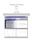
1
USER MANUAL FOR THE PROGRAM
FOIL 97
Copyright 1998,2001 Vacanti Yacht Design
All Rights Reserved
Purpose of the Program:
The program FOIL was written to allow the development of new air or hydro-foil shapes that were customized to meet the needs of special tasks. For
example, FOIL is capable of designing both symmetric and asymmetric foils shapes and then analyzing the foil lift, drag, turbulence, separation and bubble
formation characteristics of the foil. FOIL is also capable of projecting the performance of the foil when modified with a trim tab. Foil shapes designed
with this program have applications in general aviation wing and propeller design as well as applications in naval architecture for keels, rudders, wing
masts, racing hydrofoil horizontal stabilizers and power boat stabilizer wings as some examples.
Program Capabilities
FOIL uses variable order B-splines to create smooth foil shapes. The off-curve vertex control
points allow the designer the greatest flexibility to achieve the desired shape in a very
efficient manner. FOIL allows the tension or order of the B-spline to vary, thus making it
possible to make very smooth foil shape changes.
The user modifies the foil shape by moving B-spline control vertices with a mouse or
keyboard. Two plots show the relative fairness of the foil by plotting the foil curvature, and
slope of the foil curve. These curves indicate the fairness of the foil shape, and when they
change smoothly without kinks or reversing direction the foil is fair. FOIL also allows surface
normal vectors to be plotted over the foil shape to help visualize flow patterns. Examples of
foils that are fair and smooth are included and will be found in your directory labeled as
FAIR1 and FAIR2 etc.
FOIL allows using a standard NACA foil as a reference or basis to develop a new foil shape
or to create a much more accurate set of reference foil offsets for the original reference foil by
using FOIL's 48 pairs of offset data to significantly improve on the normal 26 offset pairs
provided by NACA literature. Reference NACA foil shapes are provided within FOIL and can
be selected by choosing the DRAW / HIDE REFERENCE FOIL item from the TOOL menu.
FOIL calculates area coefficient, position of maximum thickness and overall thickness in real
time as the control vertices of the foil spline are moved. Within the CALC menu list there is
facilities to calculate and wetted length, relative velocity, lift, profile drag, lift to drag ratio,
separation, turbulence, and bubble formation. A work window is provided to allow the
calculation of Reynolds numbers in Air or Water for given foil length and speed. Any
Reynolds numbers calculated in this work window are retained in memory for use in
calculating lift and drag.
Once a foil shape design is completed you may export the foil shape offsets as: DXF
compatible CAD files, Eppler ASCII text files, IGES NURB Files, CADKEY CDL files, printed
foil offsets or as special files for use in the 3D keel/wing program WINGS or the 2D program
LOFT.
Program Requirements
FOIL 97 requires Windows 98 or Windows XP or newer operating on a Pentium Class
Computer. The computer should be configured to have at least 256 MB of RAM and 10 MB
free Disk Space. FOIL 97 is a full 32 bit program and will not operate under Windows 3.x.
Installation:
A software copy protection feature that reads the configuration of the computer the software
is installed on protects all of our software. The copy protection system uses that information
to create a 16-character computer ID code. This code is then used to create a unlock code
that will lock the program to your computer. The computer ID generated by our software must
be supplied to Vacanti Yacht Design LLC who will then generate the Unlock code and send
the code back to the user. The unlock code is entered into the program and the program will
function normally.
Installation and Registration Procedure
Step 1: Turn on your printer! Our software will attempt to print a registration form.
Step 2: Install the Vacanti Yacht Design Software by running Setup.
Step 3: Run the program.
Step 4: The first time the program runs it will report that it is an unregistered copy and will
show a dialog box that contains the computer ID code and a space to enter the needed 16
character Unlock code. You may copy the 16-character ID code from the form and e-mail
([email protected]) or fax it (+425 413 2815 in USA) to Vacanti Yacht Design
Step 5: Close the dialog by clicking on the Close and Contact Vacanti…. Button. The program
will print a registration form that may be faxed to us (+425 413 2815 in USA) - or copy the
information - carefully and e-mail it to us at [email protected]
Step 6: Vacanti Yacht Design will send you the unlock code - Run the program again. The
Not Registered dialog will appear. Enter the 16-character code we have sent you in the space
provided. The code will include number 0 - 9 and letters A-F.
Step 7: Click Register or Unlock button and the program will operate normally.
Important:
If you purchase a new computer or if your hard disk is damaged or modified you must acquire
a new unlock code. We will provide one additional code per user at no cost, however you
must report the condition that caused you to require a new code. Beyond this we will charge
a fee to provide a new code.
Minor software updates to the same computer do not have to be registered.
Starting FOIL
Select FOIL 97 on the START Menu. The program will open with a blank screen. To see an
existing foil design select FILE, Open…, Select the FOIL 97 Directory and click on one of the
prepared foil names.
Program Operation
You may quickly see FOIL in operation by following these steps:
1) When FOIL begins, select FILE, OPEN….
2) Click a file name. FOIL will instantly display the selected foil file with basic characteristics
in the status line at the bottom of the screen.
3) Click CALC, then “Lift and Drag”.
4) Click OK on the calculation setup dialog.
5) FOIL 97 will plot lift vs. angle of attack. Select any other calculated value by clicking a
radio button on the right hand side of the data plot dialog.
Changing the Foil Shape
It is easy to modify the foil shape by dragging a spline control vertex with the mouse and
watch the foil shape change in real time. There are two important points to know first before
beginning.
1) A B-spline curve shape is controlled by what are called vertex control points. These
vertices are shown on screen as small triangle markers and are connected by straight lines.
They do not touch the actual foil curve except at the nose and tail. Changing the foil shape is
achieved by moving the mouse cursor over a desired vertex point and clicking and holding
the left mouse button. Now move the mouse SLOWLY. You will see the foil shape change as
the vertex control point is moved. When the mouse is released, the status line at the bottom
of the screen will be instantly updated to show the position of max thickness, actual thickness
and area coefficient. In addition, the curvature and slope lines will also be updated to indicate
the quality of the foil shape. Foil fairing information is provided later in this user manual,
however, use the higher spline tension settings (see the SPLINE Menu) to help fair the foils.
2) To modify a foil shape, move the cursor over a vertex control point. Press and hold
the left mouse button and slowly drag the mouse. Observe the location of maximum
thickness, the total thickness, the area coefficient and the fairing curves on the screen. These
pieces of information help insure that the foil you are working on achieves a needed goal. For
example, to create a foil shape that holds the greatest possible volume for ballast in a keel, or
fuel in an aircraft, adjust the foil for the maximum possible area coefficient. Pay attention to
the leading edge radius (See the Tool menu to draw a reference radius circle) to insure
beneficial lift and stall characteristics. Move the maximum thickness aft to lower drag and
move it forward to create a high lift foil that resists stalling.
Adding / Removing Camber
Any symmetric foil shape may be converted into a cambered or asymmetric foil and any
cambered foil may be converted to a symmetric shape. To add camber select from the
TOOLS menu the ADD / REMOVE CAMBER menu item. FOIL will request the location of the
maximum camber in percent of chord and the amount of camber in percent of chord. To
delete camber select ADD/REMOVE CAMBER from the TOOLS menu and the foil will be
returned to its symmetric shape.
Adding or Deleting Control Vertices
To add another control vertex to either the foil spline or the camber spline, select the SPLINE
title menu and then the “Add Foil Vertices” menu item. Select one type and the cursor will
change into an open box. The program will wait for you to position it on the foil shape. When
the cursor is in the position where you wish to add a new vertex, press the LEFT button once.
The new vertex will be added, and the foil shape will be re-plotted to show the effect of the
new vertex.
To delete a vertex, select the SPLINE menu title and then the DELETE VERTEX FROM...
menu item. FOIL will prompt for a choice of either foil or camber spline vertex. Choose FOIL
or CAMBER and the cursor will change into the open box symbol. Place the cursor over the
vertex you wish to remove and press the LEFT mouse button once. The vertex will be
removed and the new foil shape will be displayed.
Changing the B-Spline Tension
One of the most powerful features of FOIL is its ability to change the tension or smoothness
of the b-spline that defines the foil shape. The tension of a given foil is chosen automatically
by FOIL when it is designed but you may change it as follows:
Scaling a Foil
FOIL offers the ability to scale the total foil thickness. To set a foil to an exact thickness,
select the STRETCH/SHRINK FOIL menu item from the TOOLS menu. FOIL will prompt for a
new thickness in percent of chord. Type in the new value and FOIL will automatically scale
the foil to exactly that thickness. Use this function to correct the foil thickness after editing
vertex values to achieve a fair shape to the exact value desired. For a 10% thick foil, type 10
and.
Designing a New Foil
To design a new foil, select the FILE menu title and the BEGIN A NEW FOIL menu item.
FOIL will ask you for the basic dimensions of the foil you wish to design, such as the overall
thickness in percent, and the location of the maximum thickness in percent of the chord
length measured from the nose.
You may now choose to shape the foil as you desire using the mouse to move, add or delete
vertices, or you may want to use an existing NACA foil shape to use as a guide. To use a
NACA reference or other foil previously designed and saved as a WINGS file, select the
TOOLS menu and select the DRAW / ERASE REFERENCE FOIL menu item. A list of
reference foil files will shown in scrollable list. Select the foil to be used as a reference by
placing the mouse cursor on the file name and clicking the left mouse button. The reference
foil will be drawn in a new color on screen, and will serve as a guide for your new design. To
remove the reference foil, select the DRAW / ERASE REFERENCE FOIL menu item again.
The reference foil will be erased.
Fairing a Foil Shape
When you move the vertices and change the tension of the b-spline the shape of up to two
special lines drawn on screen will also change. These lines are plotting the slope of the foil
and the local curvature of the foil. These curves must be smooth and make gradual changes
in shape as shown in the foil files FAIR1 FAIR2 etc.
If the plots of lift and drag characteristics are very unusual in shape, it is very likely caused by
unfairness in the foil shape. Look very carefully at the plots in FAIR1 and FAIR2 that we have
supplied to understand these concepts.
Foil Fairing with Arrow Keys
It is critical to be able to make very small changes to the foil when trying to achieve a
particular shape or fairing. The mouse may cause the vertex to move too quickly. To use the
keys to edit the foil shape select SPLINE menu and select Move Vertex with Keys. The dialog
box above will appear. The user may now select the step size that will be assigned to each
press of an arrow key. The user may type in a step size or use the mouse to drag the slider to
the right to INCREASE the step size and to the left to decrease the step size. The actual step
size will be shown in the Key Step Size window.
Editing with the Mouse
FOIL 97 allows the user to move any vertex, at any time. Simply place the mouse cursor over
a vertex location, press the left mouse button and hold it while dragging the mouse. The foil
shape will change as the vertex is moved. The foil curvature or slope or both will also update
directly as the vertex is moved. Also notice that when the mouse stops moving, the status bar
at the bottom of the screen will indicate the new location of the maximum thickness of the foil
and the percentage thickness of the foil.
The user may select any function from any menu at any time and then return to editing the
foil shape with no need to access a menu list.
Calculate LIFT and DRAG
Select the CALC menu title and the FOIL LIFT AND DRAG menu item. And the following
dialog is presented:
This dialog permits setting the Reynolds Number range, Angles of attack and whether a flap
is attached to the trailing edge of the foil. The designer should verify that the correct range of
Reynolds numbers is listed before running the Lift / Drag Calculations. The values can be
verified or changed by clicking the “Compute New Re Numbers” button. A dialog will appear
that allows selecting operations in air or water, length of the chord of the foil, units of measure
(English or Metric) and most importantly the velocity. Be sure to choose a minimum and
maximum velocity that will match the operating speeds that the foil will see in operation. Once
the correct Reynolds numbers are computed close the Reynolds Number calculator and the
new values will appear at the left of the Calculation Settings dialog.
The designer should simply maintain the same settings for a careful set of repeated
calculations to be made as a foil shape is modified and tested for performance. The approach
to foil design should be: Create a baseline foil shape, Choose a set of operating conditions
Calculate a baseline performance data set, Modify the foil shape in one area, RE-Calculate
and compare performance.
FOIL will calculate the lift, drag, turbulence, separation, bubble formation and relative velocity
characteristics of the current foil shape over a range of angles of attack and Reynolds
numbers. You may choose to calculate performance for up to 5 Reynolds number conditions,
14 angles of attack with or without trim tab. Calculations are valid in FOIL between Reynolds
numbers of 100,000 and 20,000,000. When entering Reynolds numbers from the keyboard,
enter the number in millions. For example, enter a Reynolds number of 250,000 as 0.25 and
a Reynolds number of 1,200,000 as 1.2 .
The computed Lift Drag and
other data are presented on the
screen at left.
Output from FOIL
To generate printed outputs or
CAD exchange files, select the
OUTPUT menu. You may
choose to print a copy of the foil
drawing to a printer or to list the
foil offsets or to generate an
ASCII text file that may be read
by another program, or entered
into a word processor or many other uses. In addition it is possible to save the actual values
of lift, drag, separation, turbulence calculations in an ASCII text file that can be read and
modified by a word processing program. This function is available in the FILE menu. See the
OUTPUT menu list information in the following pages for details of the program capabilities.
DETAILS OF MENU ITEMS
FILE Menu
File, NEW – Foil Design
Select this menu item when you wish to design a new foil shape. You will be asked to supply
basic foil design criteria, such as foil thickness, leading edge radius, position of maximum
thickness and others. You will also be asked to provide a file name to identify the new foil
design. Be sure to enter foil dimensions in percent. For example when asked for the position
of maximum thickness in percent, enter 35 (for 35% aft the nose of the foil) not 0.35. The foil
designed by this process will be a symmetric foil. To create a cambered foil from this basic
form, choose the ADD/DELETE CAMBER item from the TOOLS menu.
FILE, Open…
Select a foil created earlier for viewing, editing, calculations or output functions. FOIL will
present a scrolling list of foil names from the current directory. To choose a foil from the list,
position the mouse cursor over the file name and click the left mouse button once. FOIL will
instantly load the foil from disk and display it on screen. It basic characteristics will be
displayed in the status area above the main window. To change directories, position the
mouse over the Opt menu bar and click on the left mouse button once. Select PATH from the
new menu and enter the desired path name including disk drive just as if entering it from the
dos prompt line for the Change Directory Command. FOIL will change to this new directory
and display the foils files it finds in the new directory. The scrolling list of file names has many
features that are described above in the PROGRAM OPERATION section.
SAVE
May be used at any time to save the current foil version. Use this feature to guard against
crashing the program and loosing your work, or as a way to store a file before making a
change you may want to remove later. For example, save a foil shape you are pleased with.
The foil will remain on screen and in memory.
Change the nose shape, then decide you like it in the previous version. Now bring back the
old version by selecting OPEN OLD FOIL FILE from the FILE menu and position the mouse
cursor over the file name. Click the left mouse button on the name of the current foil shape.
The original version will be displayed on screen.
SAVE AS…
Use this item to change the name of the foil currently on screen, but does not change the foil
name of the original file stored on disk. This allows one foil to become the parent shape to
many new foils. For example, select OPEN OLD FOIL FILE and click the left mouse button
on a file name. Now select RENAME THIS FILE and enter a new name. The first foil name on
disk is unchanged, but now the original foil may be changed and saved as a new foil shape
with a new name.
SAVE FOIL DATA FILE
The function is enabled if lift and drag calculations have been made for the foil currently
displayed on screen. The values plotted in graph form are available in numeric form as an
organized set of tables of data. These tables can be saved as a text file in any directory for
use later in a detailed report or for modification in a word processor or spread sheet program.
CALC Menu
FOIL AREA/LENGTH/COEFFICIENT
When this menu item is selected, the area, wetted length, and area coefficient of the current
foil on screen will be calculated. These calculated values will be printed at the bottom of the
page of printed offsets if a hard copy of this information is desired. You may select printed
offsets and foil measurements by selecting the PRINTED OFFSETS item of the OUTPUT
menu. Dimensions of wetted length and area are given in metric and English units.
The area coefficient is defined as follows: If a rectangle were drawn around the foil shape so
that it touches the leading edge, the trailing edge and the maximum thickness, the area
coefficient would be the fraction of the rectangle area that the foil covers. For example, if the
coefficient is 0.65, then the foil shape covers 65% of the rectangle that just borders it. This
means a foil with a large area coefficient would hold more tankage or ballast than a foil with a
lower coefficient. The typical range for this value is between 0.5 and 0.76.
LIFT AND DRAG
When this menu item is selected, a specially adapted version of the NASA program PROFILE
will be called to calculate the lift, drag, turbulence, separation, relative velocity and bubble
formation characteristics of the current foil shape over a range of angles of attack and
Reynolds numbers. FOIL uses default values for angle of attack and Reynolds numbers of 0
to 13 degrees in 1 degree steps and 1,2,3,4,5 Million respectively.
Once a set of Reynolds numbers, angle of attack or trim tab settings are chosen, FOIL will
maintain those values in memory making it easy to repeat calculations for each modification
of a foil shape. Therefore when FOIL presents the choice of using OLD calculation settings,
the default values will be used if you have not entered a NEW set of Reynolds numbers or
angles of attack. If the CALC menu was previously used to compute a set of Reynolds
numbers, those values will be stored in memory and used in the OLD calculation settings. If
the NEW calculation settings were previously chosen, then those values will be retained in
memory for future lift and drag computations.
Choosing NEW Calculation Settings will allow adjusting: 1) Reynolds number values 2)
Quantity of Reynolds number settings, 3) Min and max values of angle of attack, 4) Trim Tab
position and angle.
If you are not familiar with Reynolds numbers, it is a manner of expressing relative velocity in
a given fluid and with a given chord length. If you need to determine Reynolds number use
the Reynolds number calculator described below.
CALCULATE REYNOLDS NUMBER
This is the Reynolds number calculator. It will ask for a minimum speed in knots, a maximum
speed in knots, if the fluid is air or water, and then asked for a chord length. FOIL will display
5 Reynolds number values (in millions) that will be stored in memory as input values for foil lift
and drag calculations.
PERCENT CHANGE IN DATA
It may be difficult to determine from a given data plot how a design change has improved or
worsened performance. Therefore when a foil is being designed or is read in from disk, the
first time a calculation of lift and drag is made, a reference file of computed data is stored on
disk. Each successive time a calculation is made, FOIL will use the PERCENT CHANGE IN
DATA function to compute percent change in LIFT, DRAG or LIFT to DRAG Ratio based on
the very first calculation. To use this feature effectively, choose calculation conditions and a
baseline configuration of the foil first. Then calculate a lift and drag performance baseline.
Now methodically change one characteristic of the foil and recalculate lift and drag. Choose
Percent Change In Data and note the changes in each parameter. Use this function to track
your progress and guide your design changes.
DISPLAY Menu
ZOOM WINDOW
This function allows the user to use the entire screen to view a limited section of the foil. This
offers a much clearer view off which vertex point is selected etc. When this function is
selected the mouse cursor will change from a pointer into a + sign. Move the cursor to what
will become one corner of an imaginary “window”. This window will be expanded to fill the
entire screen. Now press the cursor LEFT button once quickly and release it. When you next
move the cursor a “window” will follow the cursor and change shape and size. When the
window surrounds the desired area, press the left button once and release it. The foil will be
redrawn so that the proper aspect ratio is maintained (No shape changes occur) and the
window area fills the screen.
You may repeatedly zoom on ever-smaller areas of the foil by repeatedly selecting the ZOOM
WINDOW menu item. You may turn the zoom off by selecting REDRAW FULL FOIL in the
same menu.
REDRAW FULL FOIL
This function returns the drawing to normal viewing to show the entire foil, and turns off the
Zoom Window.
DRAW / HIDE ...
This menu item provides you with a checklist menu of items that are drawn and updated on
the screen in real time. Every item that is listed with a check mark will be displayed and every
item that is not checked will be hidden. To hide or display an item in the list simply click on
the item with the left mouse button. When the items to be displayed or hidden have been
selected then click the left mouse button outside the checklist menu or press Esc. The user
may display or hide: Foil Vertices, Foil Spline, Camber Vertices, Camber Spline.
REPLOT LIFT / DRAG DATA
If calculations for the foil currently drawn on screen were made and displayed, it is possible to
review that data as often as necessary. This menu item allows the user to repeatedly display
calculated data in graphical form (x, y data plots) to allow multiple screen copies on a printer,
or simply review the data more carefully.
SPLINE Menu
ADD FOIL / CAMBER VERTICES
To add another control vertex to either the foil spline or the camber spline, select the SPLINE
title menu and then the ADD VERTICES menu item with the mouse or keyboard. When the
cursor is in the position where you wish to add a new vertex, press the LEFT button once.
The new vertex will be added, and the foil shape will be re-plotted to show the effect of the
new vertex.
DELETE FOIL / CAMBER VERTICES
To delete a vertex, select the SPLINE menu title and then the DELETE VERTEX menu item.
The cursor will change into the open box symbol. Place the cursor over the vertex you wish to
remove and press the LEFT mouse button once. The vertex will be removed and the new foil
shape will be displayed.
Changing SPLINE TENSION
This is a very powerful function of FOIL. The b-spline math of FOIL allows the use of splines
with variable tension, just like variable stiffness splines used in naval architecture. When
splines are set to the highest tension they pull away from the vertex points and are affected
far less by vertex position. When splines are set to the lowest tension, they follow the vertex
lines exactly. The tension or order of the foil spline and camber spline are displayed in the
FOIL and CAMBER tension selectors above the drawing window. Type in a new tension or
use click the up / down arrows.
The maximum tension is 5 and the lowest tension is 1. The number of vertices placed on a
spline limits the maximum tension. For example, if there are 3 vertex control points on the
Camber spline, then it will be limited to a tension of 3. If there are 5 or more vertices then the
maximum tension is 5.
TOOLS Menu
ENTER/EDIT REFERENCE FOIL
When this item is selected you will be asked to enter a file name and then enter offset data
from the keyboard. This data will be used to draw a reference foil shape on screen. This
reference shape can then be used as a template to copy exactly or to modify and calculate
the modification effects. The data file entered from the keyboard can then be recalled at any
time for tracing at a later date or it can be used as an input file to WINGS.
Entering data is similar to spreadsheet data entry. Up to 50 data points on the upper and
lower halves of the foil may be entered from the keyboard. In the lower left portion of the data
entry screen, there are two buttons. The first, SAVE & EXIT, will save the data file to disk if
two or more data points are entered. The second button UPPER/LOWER, switches the
screen display between the upper and lower halves of the foil. If the data is for a symmetric
foil, do not switch to the lower half. The data will automatically be copied into the lower half.
Asymmetric foils must have both upper and lower half data entered, and there must be an
equal number of data points on each half. The last data point in all cases must be at 100%
chord length. Switching between the upper and lower halves of an asymmetric foil may be
done at any time.
Moving within the spreadsheet can be done two ways: 1) Move the mouse cursor over the
desired data entry "cell" and click on the left mouse button once, 2) Press the up, down, right
or left arrow keys to move to the next cell.
Whether the keyboard or mouse is used to move within the spreadsheet, a data entry edit
window will be displayed with the current value of the data cell. If the data is not to be
changed, press Enter, otherwise edit the value and press Enter.
When all of the offset points have been entered, move the mouse cursor over the SAVE &
EXIT button and click the left button once.
DRAW / HIDE REFERENCE FOIL
When this item is selected, a list of reference foil names will be listed in a scrollable list. Move
the mouse cursor over the desired reference foil and press the left mouse button once. See
the PROGRAM OPERATION portion of the manual for details on using the scrolling features
of the file list. The reference foil will be drawn on screen. If a reference foil is already drawn
selecting this menu item again will erase it.
DRAW / HIDE REFERENCE NOSE RADIUS
When this item is selected enter a reference nose radius. Typically this number will range
between 0.5 and 2 percent. A circle with this radius will be drawn on screen and you may use
it to guide you in fairing the foil on screen. If a reference nose radius is already on screen
select this menu item again to erase it.
DRAW / ERASE NORMAL VECTORS
When this menu toggle item is selected either the foil normal vectors will be drawn or erased.
The normal vectors are lines that are drawn perpendicular (90 degrees) to the local foil
shape. These lines give an idea of how rapidly the foil curvature is changing. Large spaces
between the normal vectors mean that the foil is flat or unfair.
STRETCH/SHRINK FOIL
This function allows the designer to set the exact thickness of the foil in percent of chord.
Enter the desired thickness and FOIL will adjust the spline vertices to cause the foil to exactly
match the desired thickness.
AutoFit Foil to Reference Foil
This function automatically matches the foil currently being designed to a reference foil that is
drawn on screen. For example, draw a sample foil by opening an old foil file or design a new
one using File, New. Foil Design. Next use the TOOLS menu to open a reference file and
select it to be drawn. Now select the Tools menu and choose AutoFit. FOIL will show the foil
under design being matched to the reference file. The relative amount of error between the
new foil being designed and the reference foil is plotted in percentage on the bottom view
window.
Repeat selecting the AutoFit function as many times as needed to get a very accurate copy
of the reference foil. It is also ok to use the mouse or keyboard to position vertex controls in
positions that will help achieve a closer fit any time before or between runs of AutoFit.
OUTPUT Menu
PRINT FOIL DRAWING
This function will print a copy of the upper design screen on the default Windows printer or a
printer selected in the Print Setup Dialog. Choose the print setup dialog by clicking on the
Printer Setup Icon on the FOIL tool bar located above the top of the design window. The
Setup ICON shows a printer with a small wrench across it.
PRINT Offsets
A complete set of 48 offset points will be printed and at the end of the offset list, the wetted
length, area, and area coefficient values will also be printed.
Export DXF FILE
This function allows you to create either 2D DXF CAD exchange file for AUTO CAD or any
other CAD program that accepts DXF file format. (DRAFIX, DESIGN CAD, GENERIC CADD
6.0 and others) Desktop publishing programs such as Ventura, PageMaker and others also
accept the DXF format.
If you desire to place the cad file in the same directory as FOIL simply enter for example
TEST, and press enter. If you wish to place the file directly in the Auto Cad directory, type
c:\ACAD\TEST, where TEST will be the name of the file. Do not include an extension (i.e. dxf)
FOIL will do that for you.
When the process is complete, (A message will prompt you), you may select from the menu
list and create additional CAD files.
CDL FILE
This function creates a 2D CADL file to be read by CADKEY 3.0 or higher. Cadkey executes
the CADL file and draws the 2D foil shape on screen. If you desire to place the cad file in the
same directory as FOIL simply enter, for example, TEST, and press enter. If you wish to
place the file directly in the CADKEY directory, type c:\CADKEY\TEST, where TEST will be
the name of the file. Do not include an extension (i.e. .cdl) FOIL will do that for you.
After entering the file name FOIL will create the file. When the process is complete, (A
message will prompt you), you may select from the menu list and create additional CAD files.
LOFT FILE
When this item is selected you will be prompted for a file name to store offset values that can
be read by the program LOFT or recalled within FOIL as a reference foil shape. Once created
a foil design cannot be designated as a WINGS 32 foil. A WINGS 32 design must be
created by first selecting File, New, WINGS 32 from the FILE menu.
Eppler TEXT FILE
When this menu item is selected you will be asked for a file name to save the foil offsets. The
file that is saved is written in ASCII format and it may be printed, or read by another program
or edited by a word processor that recognizes the Eppler Text file format.
IGES NURB File
This standard CAD file allows an exact copy of the foil to be transferred to another CAD
program or for precision Computer Controlled Machining of the foil shape.