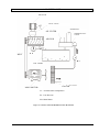
1
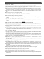
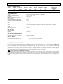
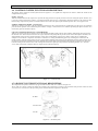
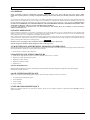
SCREW COMPRESSORS INSTRUCTION MANUAL ERA COMPACT SERIES ERA 7-10-15-20 PLEASE READ THIS MANUAL CAREFULLY BEFORE START-UP THE COMPRESSOR ERA-UM-2009-3 ROTARY SCREW AIR COMPRESSOR ERA SERIES MODEL : ...................................... SERIAL NO : ...................................... MAX . WORKING PRESSURE : ...................................... MIN. WORKING PRESSURE : ...................................... OIL TYPE ____________ : ...................................... OIL QUANTITY : ...................................... MOTOR POWER : ..............HP.............kW USER : ....................................... SOLD BY : ....................................... START-UP BY : ....................................... START-UP DATE : ....................................... INTRODUCTION DEAR ERA COMPRESSOR USER Your compressor has been produced with advanced technology and the latest engineering standards, with the experiments of years. It is mostly problem-free, efficiency and reliable if operated properly. Security must be main consideration on use as production. ERA air screw compressors have been made to produce the compressed air which is used for air tools, machines and process. Manufacturer will not be liable for applications outside the scope of the machine intended use and this will void the warranty. However, any machine might be a potential source of danger if improperly handled or use by unqualified, untrained or careless personnel or if used the scope of its intended use. Therefore, be sure to observe all instructions given in this manual and strictly comply with all local safety and accident prevention rules and regulations. DO NOT attempt to make any handling, locating, mounting, maintaining and repairing process unless read and understand this manual carefully. Your compressor may deviate a few details from the illustrations shown in this manual. This is no importance for the operation of the machine. Should any questions arise in spite of the instructions in this manual or if you have any inquiries concerning this manual or wish to obtain additional copies, please do not hesitate to contact our Technical Service Department so they will glad to help you .Make sure the manual is kept near the compressor and thus always at hand for the operating personnel. This compressor should be operated and used only by trained and qualified person. No person is allowed to operate the compressor-even for only a short time-without adequate-training. The owner should clearly establish who is responsible for assembling, disassembling and reassembling the compressor for putting it into operation, set up, operating and servicing the compressor. The owner is obligated to operate the compressor only if it is in a safe condition. Major repairs must only be carried out by the manufacturer or by specially authorised, qualified personnel. The operator is obligated to immediately remedy (if authorized) or report any defects or alterations that may affect the safety of the compressor. Product safety signs or decals should be periodically inspected and cleaned or replaced when they no longer meet the legibility requirements for safe viewing at a reasonable distance. Make sure that enclosures removed for maintenance or repairs are refitted before restarting the compressor. DO NOT remove, alter or deactivate any machine parts such as safety valve, belt guard, fan guard, extreme temperature switch, temperature switch, fuses etc. DO NOT begin any maintenance or adjustment work before the compressor has been switched off, P1 and P2 are –0- and make sure to secure the compressor against accidental restart. DO NOT use any flammable or explosive material for cleaning purposes. DO NOT allow to be any flammable gases which may cause explosion or burning in the inlet air. Keep the working area clean and tidy. Only qualified electricians are allowed to do any work on the electric system. Only use original ERA spare parts for your compressor. We assume you to keep needed spares in your stock. DO NOT allow any unauthorized companies or non-authorized companies for part changes. It is valid most restricted one of the rules about the security if any instruction in this manual is not comply with the local rules. Take additional cares if necessary and take care of each handling, operating, maintenance and repairs even tough it is not explained in this manual. Compressors must be grounded. DO NOT attempt to operate the compressor out of stated operating pressures. (operating pressure is indicated on the serial number plate) READ THE MANUAL Each authorized machine operator must have fully read the manual before working on the compressor. The person who is responsible for plant safety should request all operators to confirm this by their signature. I HAVE READ AND UNDERSTOOD THIS OPERATOR’S MANUAL Signature Date Owner ...................................... ............................................. Operators ....................................... ............................................. TABLE OF CONTENTS SECTION 1 SAFETY 1.1 1.2 1.3 1.4 1.5 1.6 1.7 1.8 1.9 1.10 GENERAL.................................................................................................................................................................... 1 PERSONAL PROTECTIVE EQUIPMENT................................................................................................................ 1 PRESSURE RELEASE................................................................................................................................................ 1 FIRE AND EXPLOSION............................................................................................................................................. 1 MOVING PART........................................................................................................................................................... 2 HOT SURFACES, SHARP EDGES AND SHARP CORNERS.................................................................................. 2 TOXIC AND IRRITATING SUBSTANCES...............................................................................................................2 ELECTRICAL SHOCK................................................................................................................................................ 2 LIFTING AND HANDLING........................................................................................................................................ 2 ENTRAPMENT............................................................................................................................................................ 3 SECTION 2 INSTALLATION 2.1 2.2 2.3 2.4 2.5 2.6 LOCATION OF COMPRESSOR...........................................................................................................................4 VENTILATION AND COOLING............................................................................................................................... 4 SERVICE AIR PIPING.................................................................................................................................................5 OIL LEVEL CHECK............................................................................................................................................5 ELECTRICAL PREPARATION.................................................................................................................................. 5 MOTOR ROTATION DIRECTION CHECK.............................................................................................................. 5 SECTION 3 SPECIFICATIONS 3.1 3.2 SPECIFICATIONS....................................................................................................................................................... 6 LUBRICATION GUIDE.............................................................................................................................................. 6 SECTION 4 COMPRESSOR SYSTEMS 4.1 4.2 4.3 4.4 4.5 4.6 4.7 4.8 INTRODUCTION......................................................................................................................................................... 7 DESCRIPTION OF COMPONENTS........................................................................................................................... 7 COMPRESSOR UNIT, FUNCTIONAL DESCRIPTION........................................................................................... 7 COMPRESSOR COOLING AND LUBRICATION SYSTEM, FUNCTIONAL DESCRIPTION............................ 7 COMPRESSOR DISHARGE SYSTEM, FUNCTIONAL DESCRIPTION................................................................ 7 CONTROL SYSTEM, FUNCTIONAL DESCRIPTION............................................................................................. 8 AIR INLET SYSTEM, FUNCTIONAL DESCRIPTION............................................................................................ 8 INSTRUMENT PANEL GROUP, FUNCTIONAL DESCRIPTION.......................................................................... 9 SECTION 5 OPERATION 5.1 5.2 5.3 INITIAL START-UP PROCEDURE........................................................................................................................... 10 SUBSEQUENT START-UP PROCEDURE............................................................................................................... 10 SHUT DOWN PROCEDURE........................................................................................................................... 10 SECTION 6 MAINTENANCE 6.1 6.2 6.3 6.4 6.5 6.6 6.7 6.8 GENERAL.................................................................................................................................................................... 11 DAILY OPERATION................................................................................................................................................... 11 MAINTENANCE AFTER INITIAL 50 HOURS OF OPERATION........................................................................... 11 MAINTENANCE EVERY 2000 HOURS.................................................................................................................... 11 OIL MAINTENANCE............................................................................................................................................. 11 OIL FILTER MAINTENANCE.............................................................................................................................. 11 SEPARATOR MAINTENANCE................................................................................................................................. 11 PARTS REPLACEMENT AND ADJUSMENT PROCEDURES............................................................................... 12 SERVICE INSTRUCTIONS FOR TREE PHASE MOTORS..................................................................................... 16 SECTION 7 TROUBLESHOOTING 7.1 7.2 INTRODUCTION......................................................................................................................................................... 17 TROUBLESHOOTING................................................................................................................................................ 17 RECOMMENDED SPARE PARTS AND SERVICE OPERATIONS…....................................................................19 SECTION 8 ILLUSTRATIONS AND PARTS LIST PROCEDURE FOR ORDERING PARTS................................................................................................................... 20 1. SAFETY 1.1 GENERAL ERA Corporation and its subsidiaries design and manufacture all of their products so they can be operated safely. However, the responsibility for safe operation rests with those who use and maintain these products. The following safety precautions are offered as a guide which, if conscientiously followed, will minimize the possibility of accidents throughout the useful life of this equipment. The compressor should be operated only by those who have been trained and delegated to do so, and who have read and understood this Operator's Manual. Failure to follow the instructions, procedures and safety precautions in this manual can result in accidents and injuries. Read this manual prior to installation, start up and maintenance. NEVER start the compressor unless it is safe to do so. DO NOT attempt to operate the compressor with a known unsafe condition. Tag the compressor and render it inoperative by disconnecting and locking out all power at source or otherwise disabling its prime mover, so others who may not know of the unsafe condition, cannot attempt to operate it until the condition is corrected. Install, use and operate the compressor only in full compliance with all applicable Federal, State and Local codes, standards and regulations. DO NOT modify the compressor and/or controls in any way except with written factory approval. 1.2 PERSONAL PROTECTIVE EQUIPMENT Before installing or operating the compressor, owners, employers and users should become familiar with, and comply with, all applicable regulations and any applicable Federal, State and Local codes, standards and regulations relative to personal protective equipment such as eye and face protective equipment, respiratory protective equipment, equipment intended to protect the extremities, protective clothing, protective shields and barriers and electrical protective equipment, as well as noise exposure administrative and/or engineering controls and/or personal hearing protective equipment. 1.3 PRESSURE RELEASE A. Install an appropriate flow limiting valve between the service air outlet and shut off valve, either at the compressor or at any other point along the air line, when an air hose exceeding 13 mm (1/2") inside diameter is to be connected to the shut off valve to reduce pressure in case of hose failure, for all applicable Federal, State and Local codes, standards and regulations. B. When the hose is to be used to supply a manifold, install an additional appropriate flow-limiting valve between the manifold and each air hose exceeding 13 mm(1/2") inside diameter that is to be connected to the manifold to reduce pressure in case of hose failure. C. Provide an appropriate flow limiting valve at the beginning of each additional hose in runs of air hose exceeding 13 mm inside diameter to reduce pressure in case of hose failure. D. Flow limiting valves are listed by pipe size and rated m3/min. Select appropriate valves accordingly in accordance with their manufacturer's recommendations. E. DO NOT use air tools that are rated below the maximum rating of the compressor. Select air tools, air hoses, pipes, valves, filters and other fittings accordingly. DO NOT exceed manufacturer's rated safe operating pressures for these items. F. Secure all hose connections by wire, chain or other suitable retaining devices to prevent tools or hose ends from being accidentally disconnected and expelled. G. Open oil filler cap only when compressor is not running and is not pressurized. Shut down the compressor and bleed the sump (receiver) pressure (P1) to zero internal pressure before removing the cap (see the sump pressure is 0 from the pressure gauge by toggling the ∆p control button). In order to prevent any burnings and injuries, wait for reducing of the oil foams in the sump tank after compressor is shut down. H. Vent all internal pressure prior to opening any line, fitting, hose, valve, drain plug, connection or other component such as filters and line oilers. I. Keep personal out of line with and away from the discharge opening of hoses or tools or other points of compressed air discharge. J. Use air at pressures less than 2,1 bar for cleaning purposes and then only with effective chip guarding and personal protective equipment. K. DO NOT engage in horseplay with air hoses as death or serious injury may result. L. DO NOT temper with sump and unit (if provided) relief valves. Check the relief valve as recommended at the Maintenance Section of this manual or at a minimum of at least weekly to make sure it is not blocked, clogged, obstructed or otherwise disabled. DO NOT change the factory setting of the relief valve 1.4 FIRE AND EXPLOSION A. Clean up spills of lubricant or other combustible substances immediately, if such spills occur. B. Shut off the compressor and allow it to cool. Then keep sparks, flames or other sources of ignition away and DO NOT permit smoking in the vicinity when checking or adding lubricant. C. DO NOT permit oils or oil film to accumulate on, under or around acoustical material, or on any external surfaces of the air compressor or on internal surfaces of the enclosure. Wipe down using an aqueous industrial cleaner or steam-clean as required. If necessary remove acoustical material, clean all surfaces and replace acoustical material. Any acoustical material with a protective covering that has been torn or punctured should be replaced immediately to prevent accumulation of the liquids or oil film within the material. DO NOT use flammable solvents for cleaning purposes. D. Disconnect and lock out all power at source prior to attempting any repairs or cleaning of the compressor or of the inside of the enclosure if any. E. Keep electrical wiring, including all terminals and pressure connectors in a good condition. Replace any wiring that has cracked, cut abraded or otherwise degraded insulation, or terminals that are worn, discoloured or corroded. Keep all terminals and pressure connectors clean and tight. F. Keep grounded and/or conductive objects such as tools away from exposed live electrical parts such as terminals to avoid arching which might serve as a source of ignition. G. Remove any acoustical material or other material that may be damaged by heat or that may support combustion and is in close proximity, prior to attempting weld repairs. H. Keep suitable fully charged fire extinguisher or extinguishers nearby when servicing and operating the compressor. I. Keep oil rags, trash, leaves, litter or other combustibles out of and away from the compressor. J. DO NOT operate the compressor without proper flow of cooling air or with inadequate flow of lubricant or with degraded lubricant. K. DO NOT attempt to operate the compressor in any classification of hazardous environment unless the compressor has been specially designed and manufactured for that duty. 1 1. SAFETY 1.5 MOVING PARTS Keep hands, arms or other parts of the body and also clothes away from pulleys and belts, fans and other moving parts. DO NOT attempt to operate the compressor with the fan, belts or other guards removed. Wear snug-fitting clothing and confine long hair when working around this compressor, especially when exposed to hot or moving parts. Keep access doors, if any, close except when making repairs and adjustments. Make sure all personal are out of and/or clear of the compressor prior to attempting to start or operate it. Disconnect and lock out all power at source and verify at the compressor that all circuits are de-energized to minimize the possibility of accidental start up or operation, prior to attempting repairs or adjustments. This is especially important when compressor are remotely controlled and remote control must be shown by signs and decals that are visible from each point of compressor G. Keep hands, feet, floors, controls and walking surfaces clean and free of oil, water or other liquids to minimize the possibility of slips and falls. A. B. C. D. E. F. H. Provide an enough illumination where compressor is installed. 1.6 HOT SURFACES, SHARP EDGES AND SHARP CORNERS A. B. C. D. Avoid body contact with hot oil, hot surfaces and sharp edges and corners. Keep all parts of the body away from all points of air discharge. Wear personal protective equipment including gloves and head covering when working in, on or around of the compressor. Keep a first aid kit handy. Seek medical assistance promptly in case of injury. DO NOT ignore small cuts and burns as they may lead to infection. 1.7 TOXIC AND IRRITATING SUBSTANCES A. DO NOT use air from this compressor for respiration (breathing) except in full compliance with any Federal, State or Local codes or regulations. DANGER! Death or serious injury can result from inhaling compressed air without using proper safety equipment. B. DO NOT use compressed air in air lines supplying respirators or other breathing air utilization equipment and DO NOT discharge air from these systems in unventilated or other confined areas. C. Operate the compressor only adequately ventilated areas. D. Locate the compressor or provide a remote inlet so that it is not likely to ingest exhaust fumes or other toxic, noxious or corrosive fumes or substances. E. Coolants and lubricants used in this compressor are typical of the industry. Care should be taken to avoid accidental ingestion and/or skin contact. In the event of ingestion, seek medical treatment promptly. Wash with soap and water in the event of skin contact. Consult the compressor operator's manual lubrication section for information pertaining to compressor oil fill. 1.8 ELECTRICAL SHOCK A. This compressor should be installed and maintained additional to this manual in full compliance with all applicable Federal, State and Local codes, standards and regulations, including those of the National Electrical Code and also including those relative to equipment grounding conductors and only by personal that are trained, qualified and delegated to do so. B. Keep all parts of the body and any hand-held tools or other conductive objects away from exposed live parts of electrical system. Maintain dry footing, stand on insulating surfaces and DO NOT contact any other portion of the compressor when making adjustments or repair to exposed live parts of the electrical system. Make all adjustments and repairs with one hand only -if possible with the right hand-, so as to minimize the possibility of creating a current path through the heart. C. Attempt repairs in clean, dry and well lightened and ventilated areas only. D. DO NOT leave the compressor unattended with open electrical enclosures. If necessary to do so, then disconnect, lock out and tag all power at source so others will not inadvertently restore power. E. Disconnect, lock out and tag all power at source prior to attempting repairs or adjustments to rotating machinery and prior to handling any ungrounded conductors. F. Dry test all shut down circuits prior to starting the compressor after installation. 1.9 LIFTING AND HANDLING A Please lift the compressor by a forklift, if possible. If there is no forklift, then lift by sling as shown in figure 1.1.Compressors to be air lifted by helicopter must not be supported by the lifting bail but by slings instead. In any event, lift and/or handle only full compliance with Federal, State and Local codes. B. Inspect points of attachment for cracked welds and for cracked, bent, corroded or otherwise degraded members and for loose bolts or nuts prior to lifting. C. Make sure entire lifting, rigging and supporting structure has been inspected, is in good condition and has a rated capacity of at least the weight of the compressor. If you are unsure of the weight, then weight compressor before lifting. D. Make sure lifting hook has a functional safety latch or equivalent, and it is fully engaged and latched on the bail or slings. E. Use guide ropes or equivalent to prevent twisting or swinging of the compressor once it has been lifted clear of the ground. F. DO NOT attempt to lift in high winds. G. Keep all personal out from under and away from the compressor whenever it is suspended. H. Lift compressor no higher than necessary. I. Keep lift operator in constant attendance whenever compressor is suspended. J. Set compressor down only on a level surface capable of safely supporting at least its weight and its loading unit. K. When moving compressor by forklift truck, utilize fork pockets if provided. Otherwise, utilize pallet if provided. If neither fork pockets or pallet are provided, then make sure compressor is secure and well balanced on forks before attempting to raise or transport in any significant distance. 2 1. SAFETY L. Make sure forklift truck forks are fully engaged and tipped back prior to lifting or transporting the compressor. M. Forklift no higher than necessary to clear obstacles at floor level and transport and corner at minimum practical speeds. N. Make sure pallet mounted compressors are firmly bolted or otherwise secured to the pallet prior to attempting to forklift or transport them. NEVER attempt to forklift a compressor that is not secured to its pallet, as uneven floors or sudden stops may cause the compressor to tumble off, possibly causing serious injury or property damage in the process. Figure 1.1 - Lifting and Handling 1.10 ENTRAPMENT A. If the compressor enclosure is large enough to hold a person and if it is necessary to enter it to perform service adjustments, inform other people before doing so, or else secure and tag the access door in the open position to avoid the possibility of others closing and possibly latching the door while somebody or some tools inside. B. Check out that, the moving parts do not touch anywhere else. C. The electrical cables should not be released without insulation. 3 2. INSTALLATION 2.1 LOCATION OF COMPRESSOR The ERA Series compressor package may be placed on any level surface capable of supporting its weight and rigid enough to maintain a level compressor frame. Level and compressor alignment is required. Floor must be protected from humidity and oil leakage which may cause to burns and corrosions. No piping loads shall be transmitted to the compressor at the external connections. Proper room and location is shown in Figure 2.1. For outside location please consult to the factory. 2.2 VENTILATION AND COOLING Select a location to permit sufficient unobstructed air flow in and out of the compressor to keep the operating temperature stable. The minimum distance that the compressor should be from surrounding walls and ceiling is 1 m or more . In order to prevent excessive ambient temperature raising, it is imperative to provide adequate ventilation. DO NOT install an air cooled after cooler where it will be exposed to temperature less than 0 °C VENTILATION REQUIREMENTS Air - Cooled Cooling Type Motor Power (kW) 2.2 3 4 5.5 7.5 11 Cooling Air Capacity (m³/h) 520 607 728 910 1100 1375 Heat Rejection (kcal/h) 1514 2064 2752 3784 5160 7568 A: Compressor B: Air Receiver C: Air Dryer D: Air Filter E : Outlet Valve 1: Flexible Hose 2: Air Pipe 3: Ball Valve 4: Drain Line Figure 2.1 - INSTALLATION 4 2. INSTALLATION 2.3 SERVICE AIR PIPING Service air piping should be installed as shown in Figure 2.1.A shut off valve should be installed to isolate the compressor from the service line. Also notice that the service line should be equipped with the condensate drains throughout the system. 2.4 OIL LEVEL CHECK Open the oil filling plug and check if the oil level is enough. If needed, add oil. For further information, look at the maintenance section. 2.5 ELECTRICAL PREPARATION Electrical wires must be selected and connected according to rated current values of the compressor as mentioned by the standards. Connections must be performed by the qualified electric technicians. Manufacturer will provide all the technical data and diagrams to the user. NOTE ! A few electrical checks should be made to help assure that the first start-up will be trouble-free. WARNING! Lethal shock hazard inside. Disconnect all power at source before opening and servicing. 1. Check incoming voltage. Be sure that compressor is wired for the correct incoming voltage. 2. Check all electrical connections for tightness. 3. Operate the compressor to check the motor rotation direction control for a short time (1-2 sec) as explained in section 2.6. 2.6 MOTOR ROTATION DIRECTION CHECK NOTE! Motor rotation check must be performed at compressor start up. As needed, remove compressor panel to view motor rotation. After the electrical wiring has been completed, it is necessary to check the direction of the motor rotation. First, see the POWER-On light is on. This light indicates that there is power at the starter. Then, checking can be done by toggling the "0"(STOP) button to "I"(START) position. When looking at the motor from the pulley side, the shaft should be turning counterclockwise. But if the air-end model is FS26, the motor should turn clockwise. (Check the sticker on the motor) If the motor turns on the wrong direction, disconnect the power to starter and exchange any two of the three power input leads then recheck rotation. A "Direction of Rotation" decal is located on the motor to show proper motor/compressor rotation. (See Figure 2.2) Figure 2.2 - Motor Rotation Direction 5 3. SPECIFICATIONS 3.1 SPECIFICATIONS MODEL POWER CAPACITY LENGTH WIDTH HEIGHT WEIGHT kW m3/min mm mm mm kg NOISE (*) dBA OPERATING PRESSURE bar COMPRESSOR TYPE AMBIENT TEMPERATURE COOLING FIRST OIL FILLED IN FACTORY OILCAPACITY MINIMUM WORKING PRESSURE MAXIMUM WORKING PRESSURE : : : : : : : OIL INJECTED ROTARY SCREW COMPRESSOR min. 0 ºC / max. 45 ºC AIR COOLED ................................................................... ....... Lt 4 bar 13,5 bar : : : : : : ..................................... B3-IP 55ASYNCHRON WITH ENCLOSURE, Three phases 380/415 V 50/60 Hz 400 V .......................... WYE-DELTA F (105 K) : : ................... 23 microns : : ................... 2-4 PPM MAXIMUM : : ………………… ……… Hz (Natural Frequency of Beltspan) MOTOR SIZE TYPE VOLTAGE SPEED STARTER INSULATION CLASS OIL FILTER PART NUMBER MICRON OIL SEPARATOR ELEMENT PART NUMBER EFFICIENCY AT MAX. CAPACITY POLY-V BELT PART NUMBER BELT TENSIONING FREQUENCY (*) Measured at 1 m acc. To the CAGI-PEUROP code. 3.2 LUBRICATION GUIDE For best value and longest uninterrupted service, the ERA compressors are factory filled and tested with a long life lubricant. MIXING OF OTHER OILS WITHIN THE COMPRESSOR WILL VOID ALL WARRANTIES. If due to availability or other reasons, other lubricants are required, follow lubrication guide from ERA. For light duty, high humidity service where condensed moisture and emulsification may occur, the oil change interval must be reduced to 300 hours maximum. A non-detergent oil with rust, oxidation and foam inhibitors and good water separation characteristics should be used. Contamination of non-detergent mineral oils with traces of detergent motor lubricants may lead to operational problems such as foaming, filter plugging orifice or line plugging. NOTE ! Flush system when switching lubricant brands. When ambient conditions exceed those noted or if conditions warrant use of "extended" life lubricants contact ERA for recommendation. ERA encourage the user to participate in a oil analysis program. This could result in a oil change interval that is different from those stated in this manual. Contact your ERA dealer for details. Maintenance of all other components is still recommended as indicated in the Operator's Manual. 6 4. COMPRESSOR SYSTEMS 4.1 INTRODUCTION Your ERA oil injected rotary screw air compressor will provide you with improved reliability and greatly reduced maintenance. 4.2 DESCRIPTION OF COMPONENTS The complete compressor consists of an compressor unit, electric motor, starter, air inlet system, compressed air discharge system, oil/air separation system, compressor lubrication and cooling system, instrument panel, all mounted in a strong cabinet. Fan draws air over the motor and forces it out through the combine aftercooler and oil cooler thereby removing the compression heat from the compressed air and the cooling oil. The compact design of the ERA Series air compressor provides easy access to all servicable components such as the oil filters and control valves. The inlet air filter is also easy accessible for servicing. 4.3 COMPRESSOR UNIT, FUNCTIONAL DESCRIPTION ERA air compressors feature the compressor unit, a single stage, positive displacement, oil-injected-type compressor. This unit provides continuous pulse-free compression to meet your needs. In the event a change of oil is required, use only ERA recommended lubricant. WARNING ! ! MIXING OF OTHER LUBRICANTS WITHIN THE COMPRESSOR UNIT WILL VOID ALL WARRANTIES! 4.4 COMPRESSOR COOLING AND LUBRICATION SYSTEM, FUNCTIONAL DESCRIPTION The cooling system consists of a fan, an oil/air cooler, separator element, oil filter, thermostatic valve, interconnecting piping and tubing and sump tank. The pressure in the air receiver / sump causes oil flow by forcing the oil from the high pressure area of the sump to a lower pressure area in the compressor unit. Oil flows from the bottom of the receiver/sump to the thermostatic valve. The thermostatic valve is fully open when the temperature is below 72 °C. Then the oil passes through the thermostatic valve, the oil filter and directly to the compressor unit when it lubricates, cools and seals the rotors and the compressor chamber. As the discharge temperature rises above 72 °C, due to the heat of compression, the thermostatic valve begins to close and a portion of the oil then flows through the cooler. Oil flows from the cooler to main filter and then on to the compressor unit. A portion of the oil flowing to the compressor is routed to the anti-friction bearings which support the rotors in the compressor unit. Prior to entering the compressor unit, this oil is taken through oil filter, thus assuring properly filtered lubricant for bearing supply. The oil flow has three basic functions: 1. As coolant, it controls the rise of air temperature normally associated with the heat of compression. 2. Seals the leakage paths between the rotors and the stator and also between the rotors themselves. 3. Acts as a lubricating film between the rotors allowing one rotor to directly drive the other, which is an idler. After the air/oil mixture is discharged from the compressor unit, the oil is separated from the air. At this time, the air flows through an after cooler, then to your service line while the oil is being cooled in preparation for reinjection. 4.5 COMPRESSOR DISCHARGE SYSTEM, FUNCTIONAL DESCRIPTION The oil receiver has two basic functions: 1. Acts as a primary oil separator. 2. Serves as the compressor oil sump. The compressed air/oil mixture enters the receiver there the velocity of the mixture is reduced and changed its direction. Thus, this allows oil to combine and to flow through the bottom of the receiver/sump. In this phase, the oil rate in the oil/air mixture is reduced. This mixture is directed to (outer bottom-side of) the separator element. Separator, with its special cardridge form, holds the oil particles moving by velocity of air and separates oil from the air. Meanwhile, some of oil leaks down in the separator element. This amount of oil is returned through the compressor unit by collecting from oil return (scavenge) line. A return (or scavenge) line leads from the (inner) bottom of the separator element to the inlet region of the compressor unit. Oil connecting on the bottom of the separator is returned to the compressor by a pressure differential between the receiver and the compressor inlet. Oil return line is composed of a transparent tube to observe this oil flow. THIS FLOW MUST BE CHECK PERIODICALLY. There is also a fitting with small orifice to prevent capacity loss due to air flow in return line, a check valve to prevent adversely flow in this return line. WARNING! DO NOT remove caps, plugs or other components when compressor is running or pressurized. Stop compressor and relieve all internal pressure before removing a part. A pressure relief valve is set to open if the sump pressure exceeds the sump tank rating. The controller will shut down the compressor if the discharge temperature reaches 115°C. (The controller uses temperature sensor for monitoring temperature at the air-end delivery point.) 7 4. COMPRESSOR SYSTEMS 4.6 CONTROL SYSTEM, FUNCTIONAL DESCRIPTION The purpose of the compressor control system shown in Figure 4.3 is to regulate the compressor air intake to match the amount of the compressed air being used. START - 0 to 4 bar When the START button of the compressor is pressed, the sump pressure will quickly rise from 0 to 4 bar. During this period, the inlet valve is open (by control solenoid valve when it is closed/de-energized) and inlet air is compressed at full rated capacity by the compressor unit. But, the rising compressed air pressure is isolated from the service line in this phase by the minimum pressure valve, set at approx. 4 bar. NORMAL OPERATING MODE - 4 to 8/10/13 bar When the air pressure rises above 4 bar, the minimum pressure check valve opens and delivers compressed air to the service line. From this point, the line air pressure can be monitored by the controller’s display. Control solenoid valve remains open during this phase. The inlet valve remains fully open for maximum capacity. UNLOAD - IN EXCESS OF 8/10/13 bar LINE PRESSURE When no air is being used, the line pressure rises to the maximum working pressure setpoint. The controller interrupts the electrical power to the solenoid valve. At this time, the solenoid valve (opens and) allows dry sump tank air pressure (at the oulet of the separator element) to be applied directly to the inlet valve piston and keep it closed. Only a small quantity of bypass air is used as control air for continuing the compressor oil circulation. Compressor will be able to continuew it’s cooling and lubricating process by circulating the air therein, in the unload condition. After the closing of the inlet valve in the unload condition of the compressor, the mimimum pressure (and non return valve) prevents line pressure from returning to the sump. When the line pressure drops to the minimum working pressure setpoint (lower limit), the controller reenergises the solenoid valve. The re-energized solenoid valve again prevents pressure from reaching the inlet valve. The inlet valve is fully open and the compressor delivers compressed air at full rated capacity. Figure 4.3 - Control System 4.7 AIR INLET SYSTEM FUNCTIONAL DESCRIPTION The compressor inlet system consists of a dry type air filter and an air inlet valve as shown on Figure 4.4. The air inlet valve directly controls the amount of air intake to the compressor in response to the operation of the pressure switch. The inlet valve also acts as a check valve, thus preventing reverse rotation when the compressor is shut down. Air filter Air inlet valve Air end Figure 4.4 - Air Inlet System 8 4. COMPRESSOR SYSTEMS 4.8 INSTRUMENT PANEL GROUP, FUNCTIONAL DESCRIPTION The AirMaster P1 controller unit has been custom designed and engineered as a cost efficient control solution for small to medium sized rotary, vane and reciprocating air compressors up to 65Bar (950psi). Interface: • • • 6 tactile feedback push button type keys integrated in to the front overlay design. Industrial push button Emergency Stop Self locking; twist to unlock. 95 element custom backlit LCD Keys: Start Up or Increment Value Stop Down or Decrement Value Reset Enter Display: 1 2 5 1: 2: 3: 4: Main Display Value Main Display Value Units User Menu Item Display Value User Menu Item Display Units 5: Status Symbols 0.1 to 999 BAR, PSI, oC, oF 0.1 to 99999 BAR, PSI, oC, oF, Hr, LHr Started, Running, Loaded 6 3 4 6: Service/Fault Symbols Alarm/Warning/Trip Service, Fault: Fault Codes: E:0010 E:0020 E:0030 E:0040 E:0050 E:0060 Emergency Stop – 24Vac in not being detected on terminal R1C C2 – fault condition detected on digital input C2 C3 – fault condition detected on digital input C3 C4 – fault condition detected on digital input C4 C5 (if set for shutdown trip function) C6 (if set for shutdown trip function) Please, read the controller manual for more information about the Air Master P1-10 Controller & Operator Panel.) 9 5. OPERATION 5.1 INITIAL START-UP PROCEDURE The following procedure should be used to make the initial start-up of the compressor: 1. Read the preceding pages of this manual. 2. Remove the red metallic brackets or the red bolts which are used for transport fixing. 3. Be sure that all preparations and checks described in the installation section have been made. 4. Open the shut off valve to the service line. 5. Energize the starter. 6. Start the compressor by pressing the START button. 7. Check motor rotation direction. 8. Check for possible oil/air leaks in piping inside and outside the compressor. 9. Slowly close the shut off valve and check that the maximum working pressure setting is correct. If the setting is correct, the compressor will unload at the desired unload pressure. Also, check safety pressure setting. If any adjustments are necessary, read the maintenance section for control system adjusment subject and also the Controller Unit Manual for other/detailed setting/adjustment procedures. 10. Observe the running parameters/status on the controller’s display, ensure the operating pressure is normal. 11. Observe the operating temperature. If the operating temperature exceeds 96 °C, the cooling system or installation environment should be checked. 12. Observe scavenge oil return/flow in the scavenge/return line transparent tube. 13. Open shut off valve to service line. 14. Reinspect the compressor for temperature and leaks the following day. 5.2 SUBSEQUENT START-UP PROCEDURE On subsequent start-ups, check that the proper oil level is in the sump tank and simply press the START button. When the compressor is running, observe the running status on control panel display. Also observe the oil flow in return (scavenge) line transparent tube. 5.3 SHUTDOWN PROCEDURE To shut the compressor down, simply press the STOP button. 10 6. MAINTENANCE 6.1 GENERAL WARNING! Before performing compressor maintenance, disconnect compressor from power source and lock out power source. Isolate compressor from line pressure by closing recommended discharge shut off valve and be sure internal pressure has blown down to zero. As you proceed in reading this section, it will be easy to see that the Maintenance program for the air compressor is quite minimal. Periodical checks and the service indicators will alert you when service maintenance is required. Read carefully before the maintenance and take care that the maintenance should be performed by the authorized person. This will increase the lifetime of your compressor. MAINTENANCE BY THE UNAUTHORIZED, NON-TRAINED PERSONS AND/OR WORKSHOPS WITHOUT PROPER ENVIRONMENT WILL VOID THE WARRANTY AND MAY CAUSE INJURIES AND ACCIDENTS. If you have any inquiries or questions after you read instructions in this manual, please do not hesitate to contact the nearest authorized technical service. 6.2 DAILY OPERATION Prior to starting the compressor, it is necessary to check the oil level in the sump. If the level is low, simply add the necessary amount. If the addition of the oil becomes too frequent, a simple problem has developed which is causing this excessive loss. See the Troubleshooting Section under Excessive Oil Consumption for a probable cause and remedy. After a start has been made, observe the instrumental panel gauges and be sure they monitor the correct reading for this particular phase of operation. After the compressor has warmed up, it is recommended that a general check on the overall compressor and instrumental panel be made to assure that the compressor is running properly. WARNING ! DO NOT remove caps, plugs or other components when compressor is running or pressurized. Stop the compressor and relieve all internal pressure before removing a part. 6.3 MAINTENANCE AFTER INITIAL 50 HOURS OF OPERATION After the initial 50 hours of operation, a few maintenance requirements are needed to clean the system from any foreign materials. Perform the following maintenance operations to prevent unnecessary problems: 1. Check if there is a leakage in the compressor. 6.4 MAINTENANCE EVERY 2000 HOURS 1. Check the scavenge/return line (orifice, check valve and tube) and clean if it is required. 2. Replace the oil filter element and the gasket. 3. Replace the air filter element. 4. Replace the separator element. 5. Replace the oil. 6.5 OIL MANTENANCE Shut down the compressor and relieve all internal pressure. Drain the sump and change the compressor oil by following the instructions stated in section 3.2 6.6 OIL FILTER MAINTENANCE Replace your oil filter element and the gasket under any of the following conditions, whichever occurs first: 1. As indicated by the maintenance guide 2. Every 2000 hours 3. Every 6 months 4. Every oil change. 6.7 SEPARATOR MAINTENANCE Replace the separator elements every 2000 hours regularly. Always use new separator elements at replacement times. DO NOT clean old separator elements. 11 6.MAINTENANCE 6.8 PARTS REPLACEMENT AND ADJUSTMENT PROCEDURES A - OIL FILTER ELEMENT REPLACEMENT (Refer to Figure 6.1) 1. Using a strap wrench, remove the old element and gasket. Clean gasket sealing surface. 2. Apply a light film of oil onto the new gasket. Add oil through the upper surface of the filter element. 3. Hand tighten new element until new gasket is seated in the gasket groove. Avoid any nicks, cuts or pinches to the gasket. 4. Restart compressor and check for the leaks. WARNING! To minimize the possibility of filter element rapture, it is important to use replacement elements ONLY identified with the ERA name, logo and appropriate part number. If original replacement elements will not be used, it may cause inadequate or questionable working pressure ratings. SEPARATOR ELEMENT OIL FILTER Figure 6.1 - Oil Filter and Separator B - AIR FILTER REPLACEMENT (Refer to Figure 6.2) Air filter element replacement should be performed every 6 months or every 2000 hours. If the filter element needs to be replaced, order this element. Replace the air filter element as described below. 1. Stop the compressor. 2. Clean exterior of air filter housing. 3. Release tension on cover clamp assembly. 4. Remove element and clean interior of housing using a damp cloth. DO NOT blow dirt out with compressed air. 5. At this time replaced the element. 6. Reassemble in the reverse order of the disassembly. C – AIR FILTER ELEMENT INSPECTION 1. Place a bright light inside the element to inspect for damage or leak holes. Concentrated light will shine through the element and disclose any holes. 2. Inspect all gaskets and gasket contact surfaces of the housing. Should faulty gaskets be evident, correct the condition immediately. 3. If the clean element is to be stored for later use, it must be stored in a clean container. After the element has been installed, inspect and tighten all air inlet connections prior to resuming operation. Figure 6.2 - Air Filter 12 6. MAINTENANCE D - SEPARATOR ELEMENT REPLACEMENT (Refer to Figure 6.1) The separator elements must be changed every 2000 hours. Follow the procedure explained below for separator element replacement: 1. Relieve all pressure from the sump tank and all compressor lines. 2. Using a strap wrench, remove the old element and gasket. Clean gasket sealing surface. 3. Hand tighten new element until new gasket is seated in the gasket groove. Avoid any nicks, cuts or pinches to the gasket. 4. Restart compressor and check for the leaks. E - CONTROL SYSTEM ADJUSTMENT Prior to adjusting the control system, it is necessary to determine the desired operation pressure range and also the maximum pressure at which your compressor is to operate. The pressure must not exceed the maximum operation pressure which is stamped on the compressor serial number plate. Start the compressor with the shut off valve nearly closed (or slightly cracked open). Compressor will change running condition from on load to off load (unload). Provide reducing alternations between these two running conditions by slightly opening the shut off valve. Observe pressure value on the controller display. When the line pressure reaches the set pressure, the controller must unload the compressor. If unloading pressure value (max. working pressure) is not the desired pressure value, working pressure upper (unloading pressure, max. working pressure) and lower (loading pressure) limits must be adjusted as it is described on Airmaster P1-10 controller manual. Please read Airmaster P1-10 Controller manual for details. F - BELT REPLACEMENT AND ADJUSTMENT (Refer to Figure 6.4) 1. 2. 3. 4. 5. 6. 7. 8. 9. 10. 11. 12. To replace the belt please perform the followings. Stop the compressor and disconnect and lock all power at source. Unscrew the belt guard. Release the tension on the belt by loosening mountage bolts (3), limiter nuts and tensioning bolts (2) of the sump tank (1). Slowly turn the belt and remove it. Be careful to not squeeze your fingers among belt and pulley. Put in place a new belt of the same model than the original. Both the belt and the pulley have grooves equally. Put these grooves in correspondence. Give some tension by tightening tensioning bolts. Adjust the belt tension and measure belt tensioning (natural frequency of beltspan) frequeny by Contitech VSM-1 or equivalent device. Ensure the frequency value is equal to the reference value which is given on Section 3, “Specifications” page of this manual. If measured frequency value is the higher than reference value, readjust the belt tension by slacking; otherwise, readjust the belt tension by streching. Tighten the mountage bolts (3) and counter nuts of the tensioning bolts (2) to lock the bolts and the sump tank as fixed, after the belt tension is OK. After the adjustment with the proper measuring tools, it is necessary to check surfaces of both pulleys for alignment. Reinspect reverse order of disassembly to reassembly. DO NOT forget to fit the guard. Check all bolts/screws and nuts again. Reenergize the compressor and start it. Check the alignment, if necessary. Sump (Separator) Tank (1) Tensioning Bolts (2) Mountage Bolts (3) Figure 6.4 – BELT TENSIONING BOLT LOCATIONS 13 6. MAINTENANCE MEASURING OF THE BELT TENSIONING FREQUENCY BY USING VSM-1 DEVICE: 1. While the compressor is not running, locate the probe at about 2 cm distance from middle top surface of the belt. 2. Direct the light of the probe onto the belt surface while vibrating middle of the belt by using finger or a proper tool. 3. Device displays the tensioning frequency as Hertz (Hz) unit. That is „Natural Frequency of Beltspan“ value and it must be equal to the reference value. If the measured frequency value is bigger than the reference value, the belt tension is more than required, if the measured frequency value is smaller than the reference valuıe, it is less than required (slack). Warning! If pulley diameters or belt length will be changed later, also, belt tensioning frequency reference value will be changed. The given reference value on the „Specifications“ page of the this manual (in Section 3) is for original factory belt-pulley configuration. It is required to refer to an authorized compressor service for a new belt tensioning frequency value for a new pulley-belt configuration OIL RETURN LINE TRANSPARENT TUBE Figure 6.5 – OIL RETURN (SCAVENGE) LINE 14 6. MAINTENANCE AIR FILTER INLET VALVE SEPERATOR OIL FILTER THERMOSTATIC VALVE AIR END BELT OIL TANK COOLER MAIN MOTOR T1: Air-End Outlet Temperature P2: Line Pressure M1: Main Motor Figure 6.6 - PIPING AND INSTRUMENTATION DIAGRAM 15 6. MAINTENANCE SERVICE INSTRUCTIONS FOR THREE- PHASE MOTORS 1. The electric motor has left our ex-works as assembled on air compressor, completed electric connection and dynamically balanced, which is ready for operation. For trouble-free, functioning care should be taken to ensure that the motors are not exposed any harmful effects during transportation and in the event of any such damage, please inform 2. When the motor has not been used for a prolonged period of time, the following work must be performed before start up Inspect the bearings and renew the grease, if necessary 3. The rotor of the motor is dynamically balanced with a fully feather key inserted in the shaft end. 4. You can prolong the service life of your motors by aligning them carefully. This applies to motors both with flexible and non-flexible couplings. Even slight misalignments may very rapidly result in damage to the bearings. Please take care that the four feet are evenly loaded. 5. Check data on the rating plate. The voltage marked on the rating plate must be in agreement with the main voltages. 6. In all of our compressors, electric motors have WYE-DELTA starter (except some special requests). So, the terminal board is normally equipped with 6 terminals. 7. Specifications VDE 0580 and VDE 0100 require that all motors to be earthed properly. Please use the special terminal in the terminal box for this purpose. 8. When operating the motor at rated voltage and rated output, the motor temperature rise at a maximum ambient temperature of 40 ºC must not exceed 80 ºC for class F insulation. 9. To avoid the danger of overloading and operation on 2 phases, motors should be protected either with thermal fuses, thermo-magnetic switches or electronic circuits. 16 7.TROUBLESHOOTING 7.1 INTRODUCTION The information contained in the troubleshooting chart is based upon both the reports about actual field applications and extensive testing done at the factory. It contains symptoms and usual causes for the described problems. However, DO NOT assume that these are the only problems that may occur. All available data concerning the trouble should be systematically analyzed before undertaking any repairs or component replacement procedures. A detailed visual inspection is worth performing for almost all problems. Doing so can prevent unnecessary damages always remember to : 1. Check for loose wiring. 2. Check for damage piping. 3. Check for parts damaged by heat or an electrical short circuit, usually apparent by discoloration or a burnt odor. If the problem persists after making the recommended check, consult your nearest ERA representative or the ERA factory. WARNING! Take care of the performing any repairs or maintenance or troubleshooting process by trained persons who know what to do, authorized service personnel by our company. 7.2 TROUBLESHOOTING SYMPTOM 1 COMPRESSOR IS NOT STARTING POSSIBLE CAUSE A Low incoming line voltage B Phases wrong C D E 2 THE COMPRESSOR IS STARTING DIFFICULTLY (OR STOP DURING START-UP). Change the positions of two phase. Reset. After heated elements cool down. Should Motor Starter Overloads trouble persist, check whether motor starter Tripped contacts are functioning properly. Line fuse blown Replace fuse. The compressor stops due to a Check the failure signal/message on the control failure panel display. A Inlet valve defective. Check and replace if needed. B Certain mechanical problems in the compressor unit Disconnect the main power and take out the belt guard. Check if you can rotate the belt easily by manually. If you can not, call the service. C Low incoming line voltage D Ambient temperature low E Pressure in the sump tank A Load inhibits problem. B Inlet valve defective THE COMPRESSOR IS NOT RUNNING 3 ON LOAD. Solenoid valve defective C / plugged Leakage in the minimum D pressure valve (can not open E A B 4 THE COMPRESSOR CAN NOT REACH THE MAXIMUM WORKING PRESSURE. REMEDY Read the Controller Unit Manual about power failure and voltage limits and related problems. C D E See 1A. See the installation section and check the ambient conditions. Check there is pressure in the sump tank before starting the compressor. After stopping the compressor, wait min. 2 minutes to discharge the pressure Read the Controller Unit Manual about load inhibits type alarms and parameter settings. The inlet valve may be malfunctioned at the close position. Check before the compressor starts. It should move easily to forward and backward by hand. Check the solenoid valve by energising it. Listen operation noise. If it is OK, remove the valve, clean or change if it is required. Sump tank pressure (P1) can not rise. Replace o-rings and seals of MPV. exactly) The setpoint of the maximum Check working pressure (maximum and mininum) working pressure (P2) is settings. Check the pressure sensor connections. wrong or pressure sensor is Replace the pressure sensor if it is defective. damaged/defective Check air leakages at air lines. If there is no Air demand is too high or air leakage you should change your compressor or add leakage new compressor. Air filter dirty Check and replace it if necessary. Check if the inlet valve is fully open at load Inlet valve damaged position. The noises of the leakages could be heard when the Air leakage in the air line or compressor is running. If there is leakage, replace pneumatic line of compressor hoses or eliminate the leakages. Mechanic failure in the air-end See 2B unit 17 7.TROUBLESHOOTING SYMPTOM POSSIBLE CAUSE A THE COMPRESSOR CAN NOT 5 UNLOAD AT MAXIMUM SET PRESSURE VALUE. B REMEDY The setpoint (P2) of the working pressure is wrong or pressure sensor may be defective Inlet valve damaged See 3E Check if the inlet valve is fully closed in unload condition. C Solenoid valve defective / plugged See 3C The orifice or strainer on the oil Clean the scavenge line with compressed air, if necessary disconnect oil return line and clean it. The separator element could be Take out the separator and check if there is hole in the separator. If necessary, replace it. A return line could be plugged THE COMPRESSOR EXHAUSTS TOO 6 MUCH OIL. B damaged or time to change C Oil leakage in the compressor D Too much oil in the compressor Set value of the thermic overload A relay is false or relay is defective. 7 MAIN MOTOR THERMIC RELAY (M1) STOPPING THE COMPRESSOR. B Low incoming line voltage Check the connections and tighten. Check and empty if needed Check the value of the thermic overload relay by checking the current of the main motor, reset it and start the compressor again and check the current of the motor if it is normal. See 1A The setpoint (P2) of the working C pressure is wrong or pressure See 3E sensor may be damaged Certain mechanical problems in D the compressor unit A Oil level too low B C D HIGH TEMPERATURE FAULT (T1) 8 STOPS THE COMPRESSOR. E See 2B Add oil Clean the surface of cooler by compressed air. If it The surface of the cooler could be is not enough clean by non-corrosive liquid plugged. cleaners. Panel filter / Air filter plugged Check the filters and replace if necessary. Check the enough ventilation so that the Ambient temperature is high compressor does not increase the temperature of the room. See installation section of the manual. The fan or the fan blades of the Check and replace if needed. compressor can be damaged F Thermostatic valve defective Change the repair kit of the thermostatic valve. The set value of temperature gauge Check the value, if necessary, change the setting. The value should be 115C Certain mechanical problems in See 2B the compressor unit The setpoint (P2) of the working pressure is wrong or pressure See 3E sensor may be damaged Inlet valve damaged See 5B The separator is plugged Check the Separator and replace if needed. G is wrong H A EXCEEDED WORKING PRESSURE. SAFETY PRESSURE SWITCH (P1) 9 STOPS THE COMPRESSOR. B C D Pressure switch (P1) damaged / set If the set value less than 1 bar, reset it. value wrong. Pressure switch (P1) damaged / set A value wrong. 10 SAFETY VALVE IS OPENING. THE COMPRESSOR CAN NOT STOP 11 ON AUTOMATIC MODE. IT IS UNABLE TO STOP THE 12 COMPRESSOR The separator is plugged damaged Safety valve damaged C defective / B / See 9D Check and replace if needed Check and replace if necessary. A Wrong working mode is selected Change the working mode. B Run on time setting is wrong Check the run on time setting in the controller program. It should about 3 to 6 minute. Start the compressor on automatic mode and check if the compressor stops. A Stop button defective Check and replace if necessary. B Contactor damaged Check and replace if necessary. 18 RECOMMENDED SPARE PARTS AND SERVICE OPERATIONS Recommended spare parts and service operations Oil - (AIRMAX 46) Oil - (AIRMAX 2000) * Air filter element Oil filter element Separator element Hydraulic hoses Pneumatic hoses Kit, inlet valve Solenoid valve Kit, contactor Kit, minimum pressure valve Kit, scavenge Thermostatic valve element O-ring, oil filling plug Belt Motor bearings Air-End revision Pressure sensor Temperature sensor Safety pressure switch 250 our 500 hours 1000 2000 or 6 months 3000 4000 5000 6000 7000 8000 or 1 year 9000 10000 110000 12000 or 18 months 13000 14000 15000 16000 or 2 years 17000 18000 19000 20000 or 30 months 21000 22000 23000 24000 or 3 years 25000 26000 27000 28000 or 42 months 29000 30000 31000 32000 or 4 years ERA COMPRESSORS - COMPACT SERIES X X X X X X X X X X X X X X X X X X X X X X X X X X X X X X X X X X X X X X X X X X X X X X X X X X X X X X X X X X X X X X X X X X X X X X X X X X X X X X X X X X X X X X X X X X X X X X X X X X X X X X X X X X X X X X X X X X X X SERVICE OPERATIONS Check oil level EVERY START-UP Check / Clean air filter element Every 1000 hours Check load / unload working conditions Every 1000 hours Check air and oil leakages Every 1000 hours Check scavenge line Every 1000 hours Check screws for electrical connections Every 2000 hours Clean cooler Every 4000 hours Check screws for connections Every 4000 hours Air-End seal leakage checking Every 8000 hours ADVISED SPARE STOCK Solenoid valve Temperature sensor Pressure sensor Working pressure switch Kit, inlet valve Kit, contactor Kit, minimum pressure valve Kit, thermostatic valve Belt Replacement times have been calculated according to normal running conditions which informed by technical specifications First section shows the changing period of components. Second section shows the checking period (*) Equivalent lubricants: ISO VG46 grade oils for rotary screw air compressors. Compressor Life Time: Compressor life is declared 10 years according to Industrial Goods’s Aftersales Service Legislation. “ERA undertakes providing spare parts of compressors for 10 years from the sales date.” 19 8. ILLUSTRATIONS AND PARTS LIST 8.1 PROCEDURE FOR ORDERING PARTS Parts should be ordered from the nearest ERA representative or the representative from whom the compressor was purchased. If for any reason parts cannot be obtained in this manner contact the factory directly at the address, fax or phone numbers below. When ordering parts, always indicate THE SERIAL NUMBER of the compressor. This can be obtained from the Bill of loading for the compressor or from the Serial number plate located on the compressor. The genuine ERA service parts listed meet or exceed the demands of this compressor. Use of replacement parts other than those approved by ERA may lead to hazardous conditions over which ERA has no control. Such conditions include, but are not limited to injury and compressor failure. www.erakompresor.com [email protected] 20