Download - Georgia Institute of Technology
Transcript
LAB L1a
Interfacing the HCS12 Microcontroller with a PC
Objectives:
1. Show how to physically connect the CML-12C32 to a host computer.
2. Learn about MON12 and understand how it is used with the HCS12.
3. Practice compiling and downloading a program to the CML-12C32.
4. Investigate the program operation by using MON12 commands.
Introduction
The purpose of this lab is to familiarize the student with how to communicate with the
HCS12 using a PC. This communication process includes the physical connections made
between the PC and the HCS12, as well as downloading, debugging, and running
assembly code.
HCS12 Background
The MC9S12 family (or HCS12) is one of the most powerful and widely used 16-bit
microprocessor families in current use. The HCS12 is far more capable and flexible than
its predecessor, the Motorola M6800 series microprocessor, as well as the Zilog Z80, the
Intel 8085 and the HC11 microprocessors which dominated the 1980's. The M6800 was
first introduced in the 1970’s. Beginning in 1984, the HC11 was initially incorporated
into a Chrysler engine control system, the Canon EOS automatic 35 mm camera, the
Delco Electronics Corp. engine control module, as well as Scientific-Atlanta's satellite
descrambler system. Since the HC11's 8-bit architecture was shown to be so flexible, the
HC11 was then incorporated into Conner Peripherals disk drive, Fisher Rosemount
digital volt meters, Ford instrument clusters, as well as Motorola cellular phones (e.g.
MicroTAC Elite personal cellular phone). Today, there are more than 60 derivatives of
the HC11 with a large variety of options. Probably one of the most popular uses of the
HC11 is within the automotive industry. A large number of automobiles use the HC11 for
the "brains" in their Electronic Control Modules (ECM's). Currently, the HC11 is found
in many Delco Electronics applications which include airbags, antilock brakes, vehicle
electronics, instrumentation, and suspension, as well as engine and transmission control.
For example Saturn's anti-lock braking system, and transmission controller are both
based on the HC11. Saturn's transmission controller works by using fuzzy logic to assist
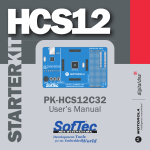
in braking on downhill grades. The actual MC9S12C MicroController Unit (MCU) is a
single-chip MCU with on-chip memory and peripheral functions, which resides on the
EVB. The EVB contains the necessary peripherals (e.g. RAM, RS-232 drivers and
receivers, etc.) which allow the user to communicate (i.e. run, debug, and evaluate
assembly code programs) with the actual HCS12 chip via a PC.
The MC9S12C (or HCS12 for short) is a 16-bit microcontroller family from Freescale
Semiconductor. Originally introduced in the mid 1990s, the architecture is an
enhancement of the Freescale 68HC11 previously described. Programs written for the
HC11 are usually compatible with the HCS12, which has a few extra instructions. Like
the 68HC11, the MC9S12C has two 8-bit accumulators A and B (referred to as a single
16-bit accumulator, D, when A & B are cascaded so as to allow for operations involving
16 bits), two 16-bit registers X and Y, a 16-bit program counter, a 16-bit stack pointer
and an 8 bit Condition Code Register.
Requirement 1A.1
Follow the steps listed below to establish communication between the HCS12 and the PC.
CML-12C32 Evaluation Board User’s Manual may be useful here.
1. Attach the serial cable (9 pin 'D') to one of the serial ports (com 1 or com 2 port) on the
back of the PC, and then to the terminal port connector on the EVB.
2. Use the included 9V wall adapter to supply power to the EVB
Communication using the “AxIDE” Program:
1. Type in the sample program, listed below, in the ASCII editor of your choice, and
save with the ASM extension (e.g. NAME.ASM). (AxIDE does not support long file
names; therefore it is better to store the file under C:\ and try not to use space for your
folder or file name)
2. Open AxIDE (There is a shortcut to the program located on the desktop)
3. When the main program window appears click on “File” then “Options,” the
“Options” dialog box should appear. In the Options dialog, change the port setting to:
baud 9600 , data bits 8, parity none, stop bits 1, and handshaking all off. Press the
“OK” button.
4. On the pull-down menu at the top of the window, select “CML12C32”
5. Press the Reset button on the EVB. The MON12 prompt (Axiom MON12 - HCS12
Monitor / Debugger. >) should appear on the PC screen. Press “E” for external
memory. If you do not get the MON12 prompt, unplug and reconnect the power
supply. If you still do not get the prompt see your TA.
6. Press the “Build” button. In the dialog box that appears, press the “browse” button
and select the file you created in step 1. Then press the “ok” button. A list file of your
program should appear. Check the list file. If there are no errors in the list file, a .S19
file with the same name of the file created in Step 1 was made (e.g. NAME.S19)
7. Type LOAD T then press [Return] (the HCS12 is now listening)
8. Select the “Upload” button.
9. In the “Upload” dialog box, click “Browse.” A file selection dialog box will appear.
10. Select the S19 file that you created and click on Ok
11. At the > prompt type GO 1000 to run your code
Requirement 1A.2
Answer the following questions explaining, possibly through examples, why each event
occurred.
1A.21 What are the contents of the stack pointer (SP) after execution of the PSHA
instruction?
1A.22 What is the status of the Z bit in the Condition Code Register (CCR) after
execution of the ANDA instruction?
1A.23 What are the contents of memory location 2000 hex after execution of the second
INC instruction?
1A.24 What is the status of the C bit in the CCR after execution of the ADDA
instruction?
1A.25 What are the contents of the stack pointer after execution of the PULA
instruction?
1A.26 Your report should include a copy of the sample program (with a title block listing
your name, lab number, and date), and the *.LST file.
Program Monitoring and Debugging using MON12
The EVB was designed along with a monitor/debugging program called MON12, which
is contained in the internal flash EEPROM (Electrically Erasable Programmable Read
Only Memory). A monitor program is a program that takes control of the computer when
it is first turned on so that it can be used. For example, in IBM-PC's and compatibles, the
monitor program starts by checking memory and then searching for a disk that contains
DOS (the Disk Operating System). On the EVB, MON12 takes control of the HCS12
upon start up and allows the user to read and write memory, as well as examine/debug
programs. Debugging is performed through the use of EVB monitor commands. These
commands can be used at the ‘>’ prompt after communication has been established with
the HCS12. Three examples are shown below. For further details of the debugger see the
“Mon12man.PDF” file located on the Axiom CD-Rom.
Register Modify command (RM). This command is used to read or modify the contents of
the HCS12's register set. This set includes the program counter (P), Y index (Y), X index
(X), A accumulator, (A), B accumulator (B), Condition Code Register (C), and stack
pointer (S) register contents.
>RM [Return]
P-1140 Y-F801 X-6FE3 A-DE B -0F C-E2 S-0054
P-1140 _
The first line is the command entered by the user. The second line is MON12 output,
which contains the current HCS12 register contents (in hex). The third line is also
MON12 output, which waits for the user to modify the contents of the program counter,
if desired. If you don’t wish to modify the register’s contents, a [Return] at this point will
return the user to the prompt without changing the contents of the program counter. To
modify the program counter contents just type in the new hex value at the cursor location
(indicated with the _ character) and press [Return]. (Note: if you want to debug your
program, starting at the first line of code, and you have just finished running your
program, you will need to reset the program counter to the starting address of your code.)
To modify the contents of any of the other registers just type the RM command followed
by a space and the letter which represents that register (e.g. >RM A [Return]).
Memory Display command (MD). This command is used to display a block of memory
specified by the user.
>MD 1150 1170 [Return]
1150 EF FF DE 23 2E E5 CD 33 45 67 BF BB 6B 4E DA A1
1160 55 41 46 72 05 00 FF E4 3B CA 67 7B 9D 33 BE B5
>
The first line is the command entered by the user. The second line is MON12 output,
which contains the current contents (in hex) of memory locations 1150 through 115F (i.e.
the contents of 1150 are EF, the contents of 1151 are FF, etc.). The third line contains the
current contents of memory locations 1160 through 116F. The user specifies the range of
addresses to display as shown above on line one. If the second address is not specified, 9
lines of memory are displayed starting at the address that was entered. The contents of
any RAM (Random Access Memory) locations can be changed using the Memory
Modify (MM) command. ROM (Read Only Memory) locations cannot be changed.
Trace command (TR or T). This command allows the user to monitor program execution
on an instruction-by-instruction basis.
>TR [Return]
Op-86
P-1102 Y-F801 X-6FE3 A-DE B -0F C-E2 S-0054
>
The first line is the command entered by the user. The second line is MON12 output,
which displays the Op-Code (Op-86) of the instruction (LDAA) at which the program
counter was pointing (1100). In this example 86 is the Op-Code for the LDAA (LoaD
Accumulator A) instruction, which is stored in memory at 1100. LDAA is a 2 byte
instruction, so it resides in memory at locations 1100 and 1101. To trace through several
lines of code type in the TR command followed by a hex number between 01 and FF (e.g.
TR 05).
Assembly programming definitions
Source Code A list of instructions (your program logic) and directives which the
assembler operates on. See sample program below.
Assembler A computer program that translates source code programs into machine
language programs that the HCS12 can use. We use the AS11 assembler which is
provided by Axiom with the EVB kit and can run on any IBM-PC or compatible.
Instruction A program command which can be executed by the HCS12 and used to
perform a logical operation. A program is a sequence of instructions, provided by the
programmer, which causes the computer (HCS12) to perform a given task.
Directive An instruction to the assembler, which is not a part of the program. The
directive directs the assembler to perform certain operations and defines the data and
variables used in the program.
Mneumonic An abridged form or acronym representing an assembly language instruction.
For example LDAA stands for LoaD Accumulator A.
Sample Program
* Program L1
* ME 4447 / ME 6405
*
* This program was written to demonstrate assembly language for the Motorola HCS12
* An * in the first column signifies that the line will be used for comments and not for
* mnemonic instructions
ORG $1000
ORG (ORiGin) is an assembler directive, which tells the assembler to assemble the code
for downloading into RAM starting at address $1000 (the $ character indicates to the
assembler that the number to follow will be in hex).
PSHA
PSHA (PuSH A) is a mnemonic instruction which tells the HCS12 to store the contents
of register A on the stack.
LDAA #%10101010
LDAA (LoaD Accumulator A) is a mnemonic instruction which tells the HCS12 to load
accumulator A with the binary number 10101010, which is equivalent to AA in hex. (The
% character indicates to the assembler that the number to follow will be in binary. The #
character indicates to the assembler that the following number is to be loaded directly
into the A accumulator. The statement LDAA $C200 would indicate to the assembler that
the value stored in memory at address C200 hex was to be loaded into the A
accumulator.)
ANDA #%01010101
ANDA (AND A) is a mnemonic instruction which tells the HCS12 to logically AND the
contents in accumulator A with the binary value 01010101 (55 in hex), and store the
result in accumulator A. The original contents in accumulator A will be overwritten.
STAA $2000
STAA (STore Accumulator A) is a mnemonic instruction which tells the HCS12 to store
the contents of accumulator A into memory at address 2000 hex.
INC $2000
INC (INCrement) is a mnemonic instruction which tells the HCS12 to increment the
contents of memory at address 2000 hex by 1.
INC $2000
INC (INCrement) is a mnemonic instruction which again tells the HCS12 to increment
the contents of memory at address 2000 hex by 1.
LDAA #$80
LDAA (LoaD Accumulator A) is a mnemonic instruction which tells the HCS12 to load
accumulator A with the hex number 80.
ADDA #$80
ADDA (ADD accumulator A) is a mnemonic instruction which tells the HCS12 to add 80
in hex to the contents of accumulator A and store the result in accumulator A. The
original contents in accumulator A will be overwritten.
LDX #100
LDX (LoaD register X) is a mnemonic instruction which tells the HCS12 to load the X
register with 100 in decimal.
DELAY DEX
DELAY is a user defined label. All labels must begin in the first column and have a
length of not more than 8 characters. DEX (DEcrement register X) is a mnemonic
instruction which tells the HCS12 to decrement the X register contents by 1.
BNE DELAY
BNE (Branch if Not Equal to zero) is a mnemonic instruction which tells the HCS12 to
branch to label DELAY if the result after execution of the last instruction was zero.
PULA
PULA (PULl A) is a mnemonic instruction which tells the HCS12 to retrieve the contents
of accumulator A which were stored on the stack with the last PSHA instruction, and
store the value in the A accumulator.
SWI
SWI (SoftWare Interrupt) is a mnemonic instruction which tells the HCS12 to store the
registers on the stack, set the I bit (the Interrupt bit) in the CCR, load the program counter
with the address stored in the SWI interrupt vector, and resume program execution at this
location. If no address is stored in the SWI vector, the main program will stop execution
at this point.
END
END (END) is an assembler directive, which tells the assembler that this is the end of the
code.
References
Georgia Institute of Technology, George W. Woodruff School of Mechanical
Engineering, “ME 4447: Control System Components, Laboratory Manual”, 1989.
Georgia Institute of Technology, George W. Woodruff School of Mechanical
Engineering, “ME 3056: Experimental Methodology, Laboratory Manual”, Summer
Quarter, 1994.
Motorola, “MC9S12C Family Reference Manual”, Motorola, Inc., Rev. 01.23, 2007.
Motorola, “MC9S12C Programming Reference Guide”, Motorola, Inc. , 2001.


