1
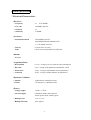
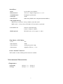
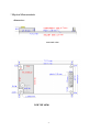
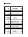
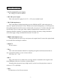
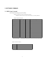
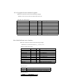
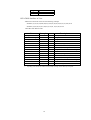
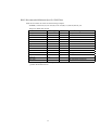
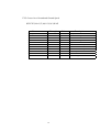
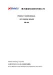
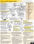
PG11 GPS
Receiver Engine Board
2005 User Manual
www.laipac.com
Laipac Technology,Inc.
55 West Beaver Creek Rd., Unit 1, Richmond Hill, Ontario, L4B 1K5 Canada
Tel:1-905-762-1228 Fax:1-905-763-1737
1.
<<Specification>>
Product Features
-- SiRF GPS Architecture
-- SiRF starII high performance and low power
consumption chip set
-- Support standard NMEA 0183 protocol
-- All-in-view 12-channel parallel processing
-- SnapLock 100ms re-acquisition time
-- Cold start under 45 seconds, average
-- Superior urban canyon performance
-- FoliageLock for weak signal tracking
-- Optional build-in SuperCap to reserve system data for
rapid satellite acquisition.
-- Full-duplex RS-232 port for navigation and control
messages
-- Differential GPS capability through 2nd RS-232 port
1
System Specification
* Electrical Characteristics
<Receiver>
-- Frequency
L1,
1575.42MHz
-- C/A code
1.023MHz chip rate
-- Channels
12
-- Sensitivity
-170dBW
<Accuracy>
-- Position Horizontal
15m 2d RMS (SA off)
10m 2d RMS,WAAS enable(SA off)
1 ~ 5 m, DGPS corrected
-- Velocity
0.1m/sec 95% (SA off),
-- Time
1 microsecond synchronized to GPS time
<Datum>
-- WGS-84
<Acquisition Rate>
-- Reacqusition
0.1 sec., average (recovery time for being interrupted)
-- Hot start
8 sec., average (with ephemeris and almanac valid)
-- Warm start
38 sec., average (with almanac but not ephemeris)
-- Cold start
48 sec., average (neither almanac nor ephemeris)
<Dynamic Condition>
-- Altitude
18,000 meters (60,000 feet) max.
– Velocity
515 meters/sec. (1000knots) max.
<Power>
-- Voltage supply
3.8Vdc ~ 6.5Vdc
-- Current supply
Continuous mode: 60mA typical
Trickle power mode: 25mA typical
-- Backup Power
+2.5V to +3.6V
-- Backup Current
10uA typical
2
<Serial Port>
-- Ports
one for GPS, one for DGPS
--Electrical level :
TTL level - Output voltage level : 0 ~ 3.5V
-- Communication
Full duplex asynchronous
-- Code type
ASCII
-- GPS Protocol
SiRF binary/NMEA 0183 changeable(Default:NMEA)
-- GPS Output Message
SiRF binary >> position, velocity, altitude, status and control
NMEA 0183 >> GGA, GSA, GSV, RMC (VTG and GLL are optional)
Software command setting
-- GPS transfer rate
(Default : 4800bps for NMEA )
-- DGPS protocol
RTCM SC-104, ver 2.00, type 1, 2, and 9
<Time Mark> (1 PPS Pulse)
-- Level
TTL
-- Pulse duration
100ms
-- Time reference
At the pulse positive edge
-- Measurement
Aligned to GPS sec., +/- 1us
<Active Antenna Connector>
--MCX ,SMA or others OEM specified connector available
* Environmental Characteristics
<Temperature>
-- Operating
-40 deg. C
to
+80 deg. C
-- Storage
-40 deg. C
to
+85 deg. C
3
* Physical Characteristics
<Dimension>
PCB SIDE VIEW
PCB TOP VIEW
4
Interface Connection
* Pin-out of the 20-pin interface connector
Pin
Number
Name
Description
Type
1
VANT
Antenna DC Voltage
Input
2
VDC
3.8V~6.5V DC Power Input
Input
3
VBAT
Backup Battery
Input
4
VDC
(Shorted with pin 2)
Input
5
PBRES
Push Button Reset Input (Active Low)
Input
6
RESERVED
7
SELECT
8
RESERVED
(Reserved)
9
RESERVED
(Reserved)
10
GND
Ground
11
TXA
Serial Data Output A (GPS Data)
Output
12
RXA
Serial Data Input A (Command)
Input
13
GND
Ground
14
TXB
Serial Data Output B (No Used)
Output
15
RXB
Serial Data Input B (DGPS Data)
Input
16
GND
Ground
17
RESERVED
(Reserved)
18
GND
Ground
19
TIMEMARK
1PPS Time Mark Output
20
RESERVED
(Reserved)
(Reserved)
Down-load data from RS232 to flash
ROM
(Reserved)
5
Output
Interface description
* VANT (antenna DC power input):
DC voltage is for active antenna.
* VDC (DC power input):
This is the main DC supply for a 3.8V ~ 6.5V power module board.
* VBAT (Backup battery):
This is the battery backup input that powers the SRAM and RTC when main power is
removed .Typical current draw is 10uA. Without an external backup battery or Gold-capacitor,
the module/engine board will execute a cold star after every turn on. To achieve the faster startup offered by a hot or warm start, either a battery backup must be connected or a Goldcapacitor should be installed. To maximize battery lifetime, the battery voltage should not
exceed the supply voltage and should be between 2.5v and 3.6v.
* PBRES (Push button reset):
This pin provides an active-low reset input to the engine board. It causes the engine board
to reset and start searching for satellites.
* SELECT :
Do not connect.
* TXA :
This is the main transmits channel for outputting navigation and measurement data to
user’s navigation software or user written software.
TTL level , 0V ~ 3.5V
* RXA :
This is the main receive channel for receiving software commands to the engine board
from SiRFdemo software or from user written software.
Normally this pin must be kept in high, and if you don’t use this pin please connect a
resistor to 3.5V to pull high.
* TXB :
No function as so far (Do not connect)
6
* RXB :
This is the auxiliary receive channel for inputting differential corrections to the engine
board to enable DGPS navigation.
* Time mark :
This pin provides one pulse-per-second output from the engine board that is synchronized
to GPS time.
* GND :
GND provides the ground for the engine board. Connect all grounds.
* Others :
Do not connect.
7
2. SOFTWARE COMMAND
2.1 NMEA Output Command
GGA-Global Positioning System Fixed Data
Table B-2 contains the values for the following example:
$GPGGA,161229.487,3723.2475,N,12158.3416,W,1,07,1.0,9.0,M,,,,0000*18
Table B-2 GGA Data Format
Name
Message ID
UTC Time
Latitude
N/S Indicator
Longitude
E/W Indicator
Position Fix Indicator
Satellites Used
HDOP
MSL Altitude1
Units
Geoid Separation1
Units
Age of Diff. Corr.
Diff. Ref. Station ID
Checksum
<CR><LF>
1.
Example
$GPGGA
161229.487
3723.2475
N
12158.3416
W
1
07
1.0
9.0
M
M
Units
Description
GGA protocol header
hhmmss.sss
ddmm.mmmm
N=north or S=south
dddmm.mmmm
E=east or W=west
See Table B-3
Range 0 to 12
Horizontal Dilution of Precision
meters
meters
meters
meters
second
Null fields when DGPS is not used
0000
*18
End of message termination
SiRF Technology Inc. does not support geoid corrections. Values are WGS84 ellipsoid heights.
Table B-3 Position Fix Indicator
Value
Description
0
Fix not available or invalid
1
GPS SPS Mode, fix valid
2
Differential GPS, SPS Mode , fix valid
3
GPS PPS Mode, fix valid
8
GLL-Geographic Position-Latitude/Longitude
Table B-4 contains the values for the following example:
$GPGLL,3723.2475,N,12158.3416,W,161229.487,A*2C
Table B-4 GLL Data Format
Name
Message ID
Latitude
N/S Indicator
Longitude
E/W Indicator
UTC Position
Status
Checksum
<CR><LF>
Example
$GPGLL
3723.2475
n
12158.3416
W
161229.487
A
*2C
Units
Description
GLL protocol header
ddmm.mmmm
N=north or S=south
dddmm.mmmm
E=east or W=west
hhmmss.sss
A=data valid or V=data not valid
End of message termination
GSA-GNSS DOP and Active Satellites
Table B-5 contains the values for the following example:
$GPGSA,A,3,07,02,26,27,09,04,15,,,,,,1.8,1.0,1.5*33
Table B-5 GSA Data Format
Name
Example
Units
Message ID
$GPGSA
Mode1
A
Mode2
3
Satellite Used1
07
Satellite Used1
02
…..
Satellite Used1
PDOP
1.8
HDOP
1.0
VDOP
1.5
Checksum
*33
<CR><LF>
1.
Satellite used in solution.
Description
GSA protocol header
See Table B-6
See Table B-7
Sv on Channel 1
Sv on Channel 2
Sv on Channel 12
Position dilution of Precision
Horizontal dilution of Precision
Vertical dilution of Precision
End of message termination
Table B-6 Mode1
Value
M
A
Description
Manual-forced to operate in 2D or 3D mode
2Dautomatic-allowed to automatically switch 2D/3D
Table B-7 Mode 2
Value
Description
9
1
2
3
Fix Not Available
2D
3D
GSV-GNSS Satellites in View
Table B-8 contains the values for the following example:
$GPGSV,2,1,07,07,79,048,42,02,51,062,43,26,36,256,42,27,27,138,42*71
$GPGSV,2,2,07,09,23,313,42,04,19,159,41,15,12,041,42*41
Table B-8 GSV Data Format
Name
Message ID
1
Number of Messages
1
Message Number
Satellites in View
Satellite ID
Elevation
Azimuth
SNR(C/No)
…….
Satellite ID
Elevation
Azimuth
SNR(C/No)
Checksum
<CR><LF>
1.
Example
$GPGSV
2
1
07
07
79
048
42
27
27
138
42
*71
Description
GSV protocol header
Range 1 to 3
Range 1 to 3
degrees
degrees
dBHz
Degrees
Degrees
dBHz
Channel 1(Range 1 to 32)
Channel 1(Maximum90)
Channel 1(True, Range 0 to 359)
Range 0 to 99,null when not tracking
…….
Channel 4 (Range 1 to 32)
Channel 4(Maximum90)
Channel 4(True, Range 0 to 359)
Range 0 to 99,null when not tracking
End of message termination
Depending on the number of satellites tracked multiple messages of GSV data may be required.
10
RMC-Recommended Minimum Specific GNSS Data
Table B-10 contains the values for the following example:
$GPRMC,161229.487,A,3723.2475,N,12158.3416,W,0.13,309.62,120598,,*10
Table B-10 RMC Data Format
Name
Message ID
UTC Time
Status
Latitude
N/S Indicator
Longitude
E/W Indicator
Speed Over Ground
Course Over Ground
Date
Magnetic Variation2
Checksum
<CR><LF>
Example
$GPRMC
161229.487
A
3723.2475
N
12158.3416
W
0.13
309.62
120598
Units
Description
RMC protocol header
hhmmss.sss
A=data valid or V=data not valid
ddmm.mmmm
N=north or S=south
dddmm.mmmm
E=east or W=west
knots
degrees
degrees
True
ddmmyy
E=east or W=west
*10
End of message termination
SiRF Technology Inc. does not support magnetic declination. All “course over ground” data are
geodetic WGS48 directions.
11
VTG-Course Over Ground and Ground Speed
$GPVTG,309.62,T,,M,0.13,N,0.2,K*6E
Name
Message ID
Course
Reference
Course
Reference
Speed
Units
Speed
Units
Checksum
<CR><LF>
Example
$GPVTG
309.62
T
Units
degrees
degrees
M
0.13
N
0.2
K
*6E
knots
Km/hr
Description
VTG protocol header
Measured heading
True
Measured heading
Magnetic
Measured horizontal speed
Knots
Measured horizontal speed
Kilometers per hour
End of message termination
12
2.2 NMEA Input Command
A). Set Serial Port
ID:100 Set PORTA parameters and protocol
This command message is used to set the protocol(SiRF Binary, NMEA, or USER1)
and/or the communication parameters(baud, data bits, stop bits, parity). Generally,this
command would be used to switch the module back to SiRF Binary protocol mode where a
more extensive command message set is available. For example,to change navigation
parameters. When a valid message is received,the parameters will be stored in battery backed
SRAM and then the receiver will restart using the saved parameters.
Format:
$PSRF100,<protocol>,<baud>,<DataBits>,<StopBits>,<Parity>*CKSUM
<CR><LF>
<protocol>
<baud>
<DataBits>
<StopBits>
<Parity>
0=SiRF Binary, 1=NMEA, 4=USER1
1200, 2400, 4800, 9600, 19200, 38400
8,7. Note that SiRF protocol is only valid f8 Data bits
0,1
0=None, 1=Odd, 2=Even
Example 1: Switch to SiRF Binary protocol at 9600,8,N,1
$PSRF100,0,9600,8,1,0*0C<CR><LF>
Example 2: Switch to User1 protocol at 38400,8,N,1
$PSRF100,4,38400,8,1,0*38<CR><LF>
**Checksum Field: The absolute value calculated by exclusive-OR the 8 data
bits of each character in the Sentence,between, but excluding “$”
and “*”. The hexadecimal value of the most significant and least
significant 4 bits of the result are convertted to two ASCII characters
(0-9,A-F) for transmission. The most
significant character is transmitted first.
**<CR><LF>
: Hex 0D 0A
13
B). Navigation lnitialization
ID:101 Parameters required for start
This command is used to initialize the module for a warm start, by providing current position
(in X, Y, Z coordinates),clock offset, and time. This enables the receiver to search for the
correct satellite signals at the correct signal parameters. Correct initialization parameters will
enable the receiver to acquire signals more quickly, and thus, produce a faster navigational
solution.
When a valid Navigation Initialization command is received, the receiver will restart using the
input parameters as a basis for satellite selection and acquisition.
Format:
$PSRF101,<X>,<Y>,<Z>,<ClkOffset>,<TimeOfWeek>,<WeekNo>,<chnlCount>,<ResetCfg>
*CKSUM<CR><LF>
<X>
<Y>
<Z>
<ClkOffset>
<TimeOf Week>
<WeekNo>
<chnlCount>
X coordinate position
INT32
Y coordinate position
INT32
Z coordinate position
INT32
Clock offset of the receiver in Hz, Use 0 for last saved
value if available. If this is unavailable, a default
value of 75000 for GSP1, 95000 for GSP 1/LX will
be used.
INT32
GPS Time Of Week
UINT32
GPS Week Number
UINT16
( Week No and Time Of Week calculation from
UTC time)
Number of channels to use.1-12. If your CPU
throughput is not high enough, you could decrease
14
needed throughput by reducing the number of
active channels
UBYTE
<ResetCfg>
bit mask
0×01=Data Valid warm/hotstarts=1
0×02=clear ephemeris warm start=1
0×04=clear memory. Cold start=1
UBYTE
Example: Start using known position and time.
$PSRF101,-2686700,-4304200,3851624,96000,497260,921,12,3*7F
C). Set DGPS Port
ID:102
Set PORT B parameters for DGPS
input
This command is used to control Serial Port B that is an input only serial port
used to receive
RTCM differential corrections.
Differential
receivers may output corrections using different
communication parameters.
The default
communication parameters for PORT B are 9600
Baud, 8data bits, 0 stop bits, and no parity.
If a DGPS
receiver is used which has different communication parameters, use this command to
allow the receiver to correctly decode the data. When a valid message is received, the
parameters will be stored in battery backed SRAM and then the receiver will restart using
the saved parameters.
Format:
$PSRF102,<Baud>,<DataBits>,<StopBits>,<Parity>*CKSUM<CR><LF>
<baud>
<DataBits>
<StopBits>
<Parity>
1200,2400,4800,9600,19200,38400
8
0,1
0=None,Odd=1,Even=2
Example: Set DGPS Port to be 9600,8,N,1
$PSRF102,9600,8,1.0*12
15
D). Query/Rate Control
and/or set output rate
ID:103
Query standard NMEA message
This command is used to control the output of standard NMEA message GGA, GLL, GSA,
GSV
RMC, VTG. Using this command message, standard NMEA message may be polled once,
or setup for periodic output. Checksums may also be enabled or disabled depending on
the needs of the receiving program. NMEA message settings are saved in battery backed
memory for each entry when the message is accepted.
Format:
$PSRF103,<msg>,<mode>,<rate>,<cksumEnable>*CKSUM<CR><LF>
<msg>
<mode>
<rate>
<cksumEnable>
0=GGA,1=GLL,2=GSA,3=GSV,4=RMC,5=VTG
0=SetRate,1=Query
Output every <rate>seconds, off=0,max=255
0=disable Checksum,1=Enable checksum for specified
message
Example 1: Query the GGA message with checksum enabled
$PSRF103,00,01,00,01*25
Example 2: Enable VTG message for a 1Hz constant output with checksum enabled
$PSRF103,05,00,01,01*20
Example 3: Disable VTG message
$PSRF103,05,00,00,01*21
16
E). LLA Navigation lnitialization
start using Lat/Lon/Alt
ID:104
Parameters required to
This command is used to initialize the module for a warm start, by providing current position
(in Latitude, Longitude, Altitude coordinates), clock offset, and time. This enables the
receiver to search for the correct satellite signals at the correct signal parameters. Correct
initialization parameters will enable the receiver to acquire signals more quickly, and thus,
will produce a faster navigational soution.
When a valid LLANavigationInitialization command is received,the receiver will restart using
the input parameters as a basis for satellite selection and acquisition.
Format:
$PSRF104,<Lat>,<Lon>,<Alt>,<ClkOffset>,<TimeOfWeek>,<WeekNo>,<ChannelCount>,
<ResetCfg>*CKSUM<CR><LF>
<Lat>
Latitude position, assumed positive north of equator and
negative south of equator float, possibly signed
<Lon>
Longitude position, it is assumed positive east of Greenwich
and negative west of Greenwich
Float, possibly signed
<Alt>
Altitude position
float, possibly signed
<ClkOffset>
Clock Offset of the receiver in Hz, use 0 for last saved value
if available. If this is unavailable, a default value of 75000
for GSP1, 95000 for GSP1/LX will be used.
INT32
<TimeOfWeek>
GPS Time Of Week
UINT32
<WeekNo>
GPS Week Number
UINT16
<ChannelCount> Number of channels to use. 1-12
UBYTE
<ResetCfg>
bit mask
0×01=Data Valid warm/hot starts=1
17
0×02=clear ephemeris warm start=1
0×04=clear memory. Cold start=1
UBYTE
Example: Start using known position and time.
$PSRF104,37.3875111,-121.97232,0,96000,237759,922,12,3*37
F). Development Data On/Off
Messages On/Off
ID:105
Switch Development Data
Use this command to enable development debug information if you are having trouble getting
commands accepted. Invalid commands will generate debug information that should
enable the user to determine the source of the command rejection. Common reasons for
input command rejection are invalid checksum or parameter out of specified range. This setting
is not preserved across a module reset.
Format: $PSRF105,<debug>*CKSUM<CR><LF>
<debug>
Example: Debug On
Example: Debug Off
0=Off,1=On
$PSRF105,1*3E
$PSRF105,0*3F
18