1
eDisplay (OP7200)
¼ VGA Operator Control Panel
User’s Manual
019–0116
• 090529–M
OP7200 User’s Manual
Part Number 019-0116 • 090529–M • Printed in U.S.A.
©2002–2009 Digi International Inc. • All rights reserved.
No part of the contents of this manual may be reproduced or transmitted in any form or by any means
without the express written permission of Digi International.
Permission is granted to make one or more copies as long as the copyright page contained therein is
included. These copies of the manuals may not be let or sold for any reason without the express written
permission of Digi International.
Digi International reserves the right to make changes and
improvements to its products without providing notice.
Trademarks
Rabbit and Dynamic C are registered trademarks of Digi International Inc.
Rabbit 2000, RabbitCore, and RabbitNet are trademarks of Digi International Inc.
The latest revision of this manual is available on the Rabbit Web site, www.rabbit.com,
for free, unregistered download.
Digi International Inc.
www.rabbit.com
eDisplay (OP7200)
TABLE OF CONTENTS
Chapter 1. Introduction
1
1.1 Features .................................................................................................................................................1
1.2 Development and Evaluation Tools......................................................................................................3
1.2.1 Tool Kit .........................................................................................................................................3
1.2.2 Software ........................................................................................................................................4
1.3 RabbitNet Peripheral Cards ..................................................................................................................5
1.4 CE Compliance .....................................................................................................................................6
1.4.1 Design Guidelines .........................................................................................................................7
1.4.2 Interfacing the OP7200 to Other Devices .....................................................................................7
Chapter 2. Getting Started
2.1
2.2
2.3
2.4
2.5
2.6
2.7
2.8
9
Power Supply Connections .................................................................................................................10
Demonstration Program on Power-Up ...............................................................................................11
Programming Cable Connections .......................................................................................................12
Installing Dynamic C ..........................................................................................................................13
Starting Dynamic C ............................................................................................................................13
PONG.C ..............................................................................................................................................14
Where Do I Go From Here? ...............................................................................................................14
Remove Battery Tab ...........................................................................................................................15
Chapter 3. Subsystems
17
3.1 OP7200 Pinouts ..................................................................................................................................18
3.1.1 Headers and Screw Terminals.....................................................................................................18
3.2 Indicators ............................................................................................................................................19
3.2.1 LEDs ...........................................................................................................................................19
3.2.2 Buzzer .........................................................................................................................................19
3.3 Digital I/O ...........................................................................................................................................20
3.3.1 Digital Inputs...............................................................................................................................20
3.3.2 Digital Outputs............................................................................................................................22
3.4 Analog Features (OP7200 only) .........................................................................................................24
3.4.1 A/D Converter Inputs..................................................................................................................24
3.4.2 Analog Current Measurements ...................................................................................................27
3.4.3 Calibrating the A/D Converter Chip ...........................................................................................28
3.4.4 Touchscreen ................................................................................................................................31
3.4.5 Analog Supply Voltage...............................................................................................................31
3.4.6 A/D Converter Reference Voltage (+V) .....................................................................................32
3.5 Serial Communication ........................................................................................................................33
3.5.1 RS-232 ........................................................................................................................................34
3.5.2 RS-485 ........................................................................................................................................34
3.5.3 RabbitNet Port.............................................................................................................................36
3.5.4 Ethernet Port ...............................................................................................................................37
3.5.5 Programming Port .......................................................................................................................38
3.6 Memory...............................................................................................................................................39
3.6.1 SRAM .........................................................................................................................................39
3.6.2 Flash Memory .............................................................................................................................39
3.7 Liquid Crystal Display Controller ......................................................................................................40
User’s Manual
3.8 Keypad ............................................................................................................................................... 41
3.9 OP7200 CPLD.................................................................................................................................... 42
3.10 Programming Cable.......................................................................................................................... 44
3.10.1 Changing Between Program Mode and Run Mode.................................................................. 44
3.11 Other Hardware ................................................................................................................................ 45
3.11.1 Spectrum Spreader.................................................................................................................... 45
Chapter 4. Software
47
4.1 Running Dynamic C........................................................................................................................... 47
4.1.1 Upgrading Dynamic C................................................................................................................ 49
4.1.2 Accessing and Downloading Dynamic C Libraries ................................................................... 50
4.2 Font and Bitmap Converter ................................................................................................................ 51
4.3 Sample Programs................................................................................................................................ 52
4.3.1 General OP7200 Sample Programs ............................................................................................ 52
4.3.2 Digital I/O................................................................................................................................... 52
4.3.3 Serial Communication ................................................................................................................ 53
4.3.4 A/D Converter Inputs ................................................................................................................. 54
4.3.5 Graphic Display.......................................................................................................................... 55
4.3.6 Keypad........................................................................................................................................ 55
4.3.7 Touchscreen (OP7200 only)....................................................................................................... 55
4.3.8 Using System Information from the RabbitCore Module .......................................................... 56
4.4 OP7200 Libraries ............................................................................................................................... 57
4.5 OP7200 Function APIs....................................................................................................................... 58
4.5.1 Board Initialization ..................................................................................................................... 58
4.5.2 Digital I/O................................................................................................................................... 59
4.5.3 LEDs........................................................................................................................................... 62
4.5.4 Serial Communication ................................................................................................................ 63
4.5.5 A/D Converter Inputs (OP7200 only) ........................................................................................ 65
4.5.6 Graphic Display Functions ......................................................................................................... 75
4.5.7 Keypad Functions....................................................................................................................... 96
4.6 Touchscreen (OP7200 only)............................................................................................................... 99
4.7 RabbitNet Port.................................................................................................................................. 111
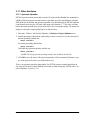
Chapter 5. Using the TCP/IP Features
113
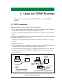
5.1 TCP/IP Connections ......................................................................................................................... 113
5.2 TCP/IP Sample Programs................................................................................................................. 115
5.2.1 How to Set IP Addresses in the Sample Programs................................................................... 115
5.2.2 How to Set Up Your Computer for Direct Connect ................................................................. 116
5.2.3 Run the PINGME.C Demo....................................................................................................... 117
5.2.4 Running More Demo Programs With a Direct Connection ..................................................... 118
5.3 Where Do I Go From Here? ............................................................................................................. 119
Chapter 6. Installation, Mounting, and Care Guidelines
121
6.1 Grounding......................................................................................................................................... 121
6.2 Installation Guidelines...................................................................................................................... 122
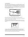
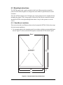
6.3 Mounting Instructions ...................................................................................................................... 123
6.3.1 Bezel-Mount Installation .......................................................................................................... 123
6.4 Care Guidelines ................................................................................................................................ 125
Appendix A. Specifications
127
A.1 Electrical and Mechanical Specifications........................................................................................ 128
A.1.1 Physical Mounting................................................................................................................... 130
A.2 Conformal Coating .......................................................................................................................... 131
A.3 Jumper Configurations .................................................................................................................... 132
A.4 Use of Rabbit 2000 Parallel Ports ................................................................................................... 135
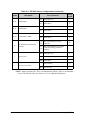
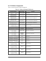
A.5 I/O Address Assignments................................................................................................................ 137
eDisplay (OP7200)
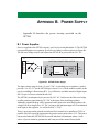
Appendix B. Power Supply
139
B.1 Power Supplies.................................................................................................................................139
B.1.1 Power for Analog Circuits........................................................................................................140
B.1.2 Grounds ....................................................................................................................................140
B.1.3 RabbitNet Power Supplies........................................................................................................140
B.2 Batteries and External Battery Connections ....................................................................................141
B.2.1 Replacing the Backup Battery ..................................................................................................141
B.2.2 External Battery........................................................................................................................142
B.2.3 Battery-Backup Circuit.............................................................................................................143
B.2.4 Power to VRAM Switch...........................................................................................................144
B.2.5 Reset Generator ........................................................................................................................144
B.3 Chip Select Circuit ...........................................................................................................................145
Appendix C. Demonstration Board Connections
147
C.1 Connecting Demonstration Board....................................................................................................147
Appendix D. RabbitNet
151
D.1 General RabbitNet Description........................................................................................................151
D.1.1 RabbitNet Connections ............................................................................................................151
D.1.2 RabbitNet Peripheral Cards......................................................................................................152
D.2 Physical Implementation..................................................................................................................153
D.2.1 Control and Routing .................................................................................................................153
D.3 Function Calls ..................................................................................................................................154
D.3.1 Status Byte ...............................................................................................................................160
Index
161
Schematics
165
User’s Manual
eDisplay (OP7200)
1. INTRODUCTION
The OP7200 intelligent operator interface is a small, highperformance, C-programmable data acquisition and display unit
that offers built-in I/O, Ethernet connectivity, and an optional
touchscreen. The OP7200 can be used in a control system with
RabbitNet™ expansion I/O cards. A Rabbit® 2000 microprocessor
operating at 22.1 MHz provides fast data processing.
The OP7200 is designed for panel mounting and is NEMA-4
compatible. The OP7200 incorporates the powerful Rabbit 2000
microprocessor, flash memory, static RAM, industrialized digital I/O ports, RS-232/RS-485 serial ports, a 10/100-compatible
Ethernet port, and eight optional A/D converter inputs and
touchscreen.
1.1 Features
• Small size: 4.4" × 5.7" × 1.7" (112 mm × 144 mm × 43 mm).
• ¼ VGA LCM display (320 × 240 pixels) with white LED backlight.
• Software-controlled LCD contrast and backlight on/off.
• 9-key keypad.
• LCD controller and SRAM compatible with OP7100.
• 4 status LEDs.
• 24 digital I/O: 16 filtered digital inputs with an input range of ±36 V DC and a switching point of 2.4 V, and 8 sourcing/sinking/tristate high-current outputs (250/350/0 mA).
• Rabbit 2000 microprocessor operating at 22.1 MHz.
• Audible alarm buzzer.
• 128K static RAM and 256K flash memory standard.
• One RJ-45 10/100-compatible Ethernet port with a 10Base-T Ethernet interface.
User’s Manual
1
• Four serial ports (2 RS-232 or 1 RS-232 with RTS/CTS, 1 RS-485 or RabbitNet™
expansion port, and 1 CMOS-compatible programming port).
• Onboard backup battery for real-time clock and SRAM, connection point for external
battery included.
• Watchdog.
• External reset input.
• Meets NEMA 4 watertightness specifications when front-panel mounted.
• Optional 8-channel 12-bit A/D converter.
• Optional 4096 × 4096 analog touchscreen.
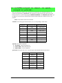
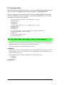
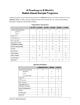
Two OP7200 models are available. Their standard features are summarized in Table 1.
Table 1. OP7200 Models
Feature
Microprocessor
OP7200
OP7210
Rabbit 2000 running at 22.1 MHz
Static RAM
128K
Flash Memory
256K
RJ-45 Ethernet Connector and
Filter Capacitors
Yes
RabbitCore Module Used
RCM2200
A/D Converter Inputs
Yes
No
4096 × 4096 Touchscreen
Yes
No
Additional 512K flash/512K SRAM memory options are available for custom orders
involving nominal lead times. Contact your Rabbit sales representative or authorized
distributor for more information.
Throughout this manual, the term OP7200 refers to the complete series of OP7200 operator interfaces unless other production models are referred to specifically.
Appendix A provides detailed specifications.
Visit our Web site for up-to-date information about additional add-ons and features as
they become available. The Web site also has the latest revision of this user’s manual.
2
eDisplay (OP7200)
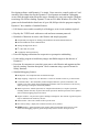
1.2 Development and Evaluation Tools
1.2.1 Tool Kit
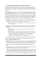
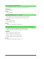
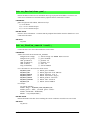
A Tool Kit contains the hardware essentials you will need to use your OP7200. The items
in the Tool Kit and their use are as follows.
• OP7200 Getting Started instructions.
• Dynamic C CD-ROM, with complete product documentation on disk.
• Programming cable, used to connect your PC serial port to the OP7200.
• Universal AC adapter, 12 V DC, 1 A (includes Canada/Japan/U.S., Australia/N.Z.,
U.K., and European style plugs).
• Demonstration Board with pushbutton switches and LEDs. The Demonstration Board
can be hooked up to the OP7200 to demonstrate the I/O.
• Wire assembly to connect Demonstration Board to OP7200.
• Screwdriver.
• Rabbit 2000 Processor Easy Reference poster.
• Registration card.
DIAG
Programming
Cable
Universal
AC Adapter
with Plugs
PROG
Screwdriver
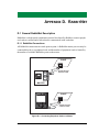
eDisplay (OP7200)
The OP7200 intelligent operator interface is a small, high-performance, C-programmable data acquisition
and display unit that offers built-in I/O, Ethernet connectivity, and an optional touchscreen. These Getting
Started instructions included with the Tool Kit will help you get your OP7200 up and running so that you
can run the sample programs to explore its capabilities and develop your own applications.
Tool Kit Contents
Demo Board
Wire
The OP7200 Tool Kit contains the following items:
• Dynamic C CD-ROM, with complete product documentation on disk.
• Demonstration Board with pushbutton switches and LEDs.
• Wire assembly to connect Demonstration Board to OP7200.
• Programming cable, used to connect your PC serial port to the OP7200.
• Universal AC adapter, 12 V DC, 1 A (includes Canada/Japan/U.S., Australia/N.Z., U.K., and European
style plugs).
• Screwdriver.
• Getting Started instructions.
• Rabbit 2000 Processor Easy Reference poster.
• Registration card.
J1
·
·
·
·
·
·
·
·
·
·
·
·
Visit our online Rabbit store at www.rabbit.com/store/ for the latest information on peripherals and accessories that are available for the OP7200 operator interface.
H2
Before doing any development, you must install Dynamic C. Insert the CD from the Tool Kit in your PC’s
CD-ROM drive. If the installation does not auto-start, run the setup.exe program in the root directory
of the Dynamic C CD. Install any Dynamic C modules after you install Dynamic C.
LED1 LED2 LED3 LED4
SW4
BUZZER
H
SW3
1
SW2
2-
SW1
· ·1
· · 8-7
· · 6-5
· · 4-3
· · 1-2
· · 3-4 DEMO BOARD
· · 5-6
Rabbit and Dynamic C are registered trademarks of Digi International Inc.
Getting Started
Instructions
B
U
Z
LE ZE
D R
L 4
E
D
LE 3
D
LE 2
D
K 1
+5
V
S
W
4
SW
3
S
W
2
SW
1
G
N
D
Step 1 — Install Dynamic C®
Demo Board
Figure 1. OP7200 Tool Kit
User’s Manual
3
1.2.2 Software
The OP7200 is programmed using version 7.30 or later of Rabbit’s Dynamic C. A compatible version is included on the Tool Kit CD-ROM. Dynamic C v. 9.60 includes the popular
µC/OS-II real-time operating system, point-to-point protocol (PPP), FAT file system, RabbitWeb, and other select libraries that were previously sold as individual Dynamic C modules.
Rabbit also offers for purchase the Rabbit Embedded Security Pack featuring the Secure
Sockets Layer (SSL) and a specific Advanced Encryption Standard (AES) library. In addition to the Web-based technical support included at no extra charge, a one-year telephonebased technical support subscription is also available for purchase. Visit our Web site at
www.rabbit.com for further information and complete documentation, or contact your
Rabbit sales representative or authorized distributor.
4
eDisplay (OP7200)
1.3 RabbitNet Peripheral Cards
RabbitNet™ is an SPI serial protocol that uses a robust RS-422 differential signalling interface (twisted-pair differential signaling) to run at a fast 1 Megabit per second serial rate. The
OP7200 has one RabbitNet port, which can support one peripheral card. Distances between a
master processor unit and peripheral cards can be up to 10 m or 33 ft.
The following low-cost peripheral cards are currently available.
• Digital I/O
• A/D converter
• D/A converter
• Display/Keypad interface
• Relay card
Appendix D provides additional information on RabbitNet peripheral cards and the RabbitNet protocol. Visit our Web site for up-to-date information about additional add-ons and features as they become available.
User’s Manual
5
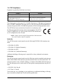
1.4 CE Compliance
Equipment is generally divided into two classes.
CLASS A
CLASS B
Digital equipment meant for light industrial use
Digital equipment meant for home use
Less restrictive emissions requirement:
less than 40 dB µV/m at 10 m
(40 dB relative to 1 µV/m) or 300 µV/m
More restrictive emissions requirement:
30 dB µV/m at 10 m or 100 µV/m
These limits apply over the range of 30–230 MHz. The limits are 7 dB higher for frequencies
above 230 MHz. Although the test range goes to 1 GHz, the emissions from Rabbit-based
systems at frequencies above 300 MHz are generally well below background noise levels.
The OP7200 has been tested and was found to be in conformity with
the following applicable immunity and emission standards. The OP7210
is also CE qualified as it is a sub-version of the OP7200. Boards that
are CE-compliant have the CE mark.
NOTE: Earlier versions of the OP7200 sold before 2003 that do not
have the CE mark are not CE-compliant.
Immunity
The OP7200 operator control panels meet the following EN55024/1998 immunity standards.
• EN61000-4-2 (ESD)
• EN61000-4-3 (Radiated Immunity)
• EN61000-4-4 (EFT)
• EN61000-4-6 (Conducted Immunity)
Additional shielding or filtering may be required for a heavy industrial environment.
Emissions
The OP7200 operator control panels meet the following emission standards emission standards with the Rabbit 2000 spectrum spreader turned on and set to the normal mode. The
spectrum spreader is only available with Rev. C or higher of the Rabbit 2000 microprocessor. This microprocessor is used on the OP7200 operator control panels that carry the CE
mark.
• EN55022:1998 Class B
• FCC Part 15 Class B
Your results may vary, depending on your application, so additional shielding or filtering
may be needed to maintain the Class B emission qualification.
6
eDisplay (OP7200)
1.4.1 Design Guidelines
Note the following requirements for incorporating the OP7200 operator control panels
into your application to comply with CE requirements.
General
• The power supply provided with the Tool Kit is for development purposes only. It is the
customer’s responsibility to provide a CE-compliant power supply for the end-product
application.
• When connecting the OP7200 to outdoor cables, the customer is responsible for providing CE-approved surge/lightning protection.
• Rabbit recommends placing digital I/O or analog cables that are 3 m or longer in a
metal conduit to assist in maintaining CE compliance and to conform to good cable
design practices. Rabbit also recommends using properly shielded I/O cables in noisy
electromagnetic environments.
• While the OP7200 meets the EN61000-4-2 (ESD) requirements in that it can withstand
contact discharges of ± 4 kV and air discharges of ± 8 kV, it is the responsibility of the
end-user to use proper ESD precautions to prevent ESD damage when installing or servicing the OP7200.
• To meet electromagnetic compatibility requirements, and in particular to prevent misoperation or damage from electrostatic discharges, connect the bezel to a protective
ground via a low-impedance path as explained in Section 6.1.
Safety
• For personal safety, all inputs and outputs to and from the OP7200 must not be connected to voltages exceeding SELV levels (42.4 V AC peak, or 60 V DC). Damage to
the Rabbit 2000 microprocessor may result if voltages outside the design range of 0 V
to 5.5 V DC are applied directly to any of its digital inputs.
• The lithium backup battery circuit on the OP7200 has been designed to protect the battery from hazardous conditions such as reverse charging and excessive current flows.
Do not disable the safety features of the design.
1.4.2 Interfacing the OP7200 to Other Devices
Since the OP7200 operator control panels are designed to be connected to other devices,
good EMC practices should be followed to ensure compliance. CE compliance is ultimately the responsibility of the integrator. Additional information, tips, and technical
assistance are available from your authorized Rabbit distributor, and are also available on
our Web site at www.rabbit.com.
User’s Manual
7
8
eDisplay (OP7200)
2. GETTING STARTED
Chapter 2 explains how to connect the programming cable and
power supply to the OP7200.
User’s Manual
9
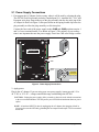
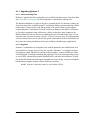
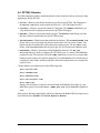
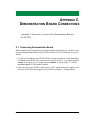
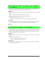
2.1 Power Supply Connections
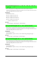
1. First prepare the AC adapter for the country where it will be used by selecting the plug.
The OP7200 Tool Kit presently includes Canada/Japan/U.S., Australia/N.Z., U.K., and
European style plugs. Snap in the top of the plug assembly into the slot at the top of the
AC adapter as shown in Figure 2, then press down on the spring-loaded clip below the
plug assembly to allow the plug assembly to click into place.
Connect the bare ends of the power supply to the +PWR and -PWR positions on pins 1
and 2 of screw terminal header J3 as shown in Figure 2. The polarity of your connections is not important because the power-supply circuit has a full-wave bridge rectifier.
USR
PWR
R37
R39
D8
Q11
C16
C30
D9
OUT0
R55
Q10
RXD
R89
R85
R84
R83
R82
IN6
C40
TXD
J10
Q31
RXC
R36
R169
TXC
R87
R162
R88
IN5
R86
JP9
IN4
R165
R164
IN7
R71
IN15
RESET
input
1
IN11
IN13
IN12
IN10
C50
C51
LNK
J12
ACT 1
J10
JP3
IN9
R90
C48
J15
E-Net
Remove slot cover,
insert tab into slot
Assemble
AC Adapter
IN14
IN8
R72
R59
R60
R66
J6
GND
485
R149
J16
PROG
J9
C84
IN3
1
C43
C85
R79
R78
R77
R76
R75
R74
C36
IN2
J1
JP2
IN1
D24
GND
D11
D10
R151
R152
IN0
J8
L9
1
D20
+485
J6
C82
R81
R80
/RST
JP7
J2
D23
C39
L2 C31
+K
+
PWR
C13
C49
+PWR
R64
R62
AGND
1
R65
R45
AIN7
Q13
C29 C86
R56
R43
AIN6
Battery
C18
C17
D6
SLAVE
LS1
GND
OUT7
J3
Q6
OUT6
OUT5
D4
4
OUT4
R38
2
3
C32
C44
C8
C6
D5
Q7
MSTR
1
Q12
R46
Q8
OUT3
R22
R147
AIN5
R40 R42
J7
Q3
D2
C66
JP10
JP6
AIN4
CAUTION: Disconnect J14
power
before making or removing
terminal connections.
C7
OUT2
R23
JP5
R27 R30
AIN3
R29
R31
R41
R44
R14
D3
C57
AIN2
JP8
R159
J2
C65
R108
AIN1
R19 R26
JP4
R61
R25
R28
Q4
OUT1
R24
C2
AIN0
C60
R16
R17
C61
C4
C33
R15
IN18
R18
IN17
Y1
D1
Q2
60
J3
R91
TVS1
C1
JP1
1
U2
DS2
1
D15
J13
C5
R2
R1
IN16
R20
D14
D12
DS1
Q5
D13
2
Snap plug into place
R-Net
Figure 2. Power Supply Connections
2. Apply power.
Plug in the AC adapter. If you are using your own power supply, it must provide 9 V to
40 V DC or 24 V AC—voltages outside this range could damage the OP7200.
CAUTION: Unplug the power supply while you make or otherwise work with the connections
to the screw-terminal headers. This will protect your OP7200 from inadvertent shorts or power
spikes.
NOTE: A hardware RESET is done by unplugging the AC adapter, then plugging it back in.
You may also reset the OP7200 by grounding the reset input located on pin 5 of screw-terminal
header J10.
10
eDisplay (OP7200)
2.2 Demonstration Program on Power-Up
A repeating sequence of graphics and menus will be displayed on the LCD when power is
first applied to the OP7200. Press any of the five keypad buttons immediately below the
LCD to select the corresponding demonstration. When you are in a menu demo screen,
press the diamond-shaped keypad button in the middle row to enter the menu choice that
is highlighted, or press the up and down keys above and below the diamond-shaped keypad button to move around the menu.
Note that the programming cable should not be connected for this demonstration.
This demonstration will be replaced by a new program when the programming cable is
attached and the new program is compiled and run. The demonstration is available for
future reference in the Dynamic C SAMPLES\OP7200 directory as FUN.C.
User’s Manual
11
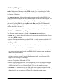
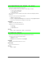
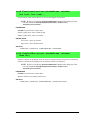
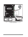
2.3 Programming Cable Connections
Connect the programming cable to download programs from your PC and to program and
debug the OP7200.
NOTE: Use only the programming cable that has a red shrink wrap around the RS-232
level converter (Part No. 101-0513), which is supplied with the OP7200 Tool Kit. Other
Rabbit programming cables might not be voltage-compatible or their connector sizes
may be different.
Connect the 10-pin PROG connector of the programming cable to header J1 on the
OP7200’s RabbitCore module. Ensure that the colored edge lines up with pin 1 as shown.
(Do not use the DIAG connector, which is used for monitoring only.) Connect the other end
of the programming cable to a COM port on your PC. Make a note of the port to which
you connect the cable, as Dynamic C will need to have this parameter configured. Note
that COM1 on the PC is the default COM port used by Dynamic C.
J1
PROG
NOTE: Never disconnect the programming cable
by pulling on the ribbon cable. Carefully pull on
the connector to remove it from the header.
USR
J3
D
OUT6
D2
OUT5
OUT4
D5
OUT3
D4
OUT2
D6
OUT1
D8
OUT0
D9
+K
C29
C8
6
R62
R65
+PWR
D20
TVS1
D
GN
R149
+485
C84
485
RXD
JP6
GND
EGND
TXD
RXC
TXC
C40
R-Net
R71
R72
R59
R60
R66
DS1
LNK
IN10
IN13
DS2
/RST
JP1
IN15
C29 GND
1
IN14
R36
R169
C30
JP2
Q31
JP5
Y3
GN
D3
R23
R37
R16
OUT7
R24
R38
C14
ACT
JP9
LNK
E-Net
D23
C85
R151
R152
JP3
JP4
R165
R164
R162
C25
R21 R22
R90
J10
C7
J16
Fla
EPRsh
OM
R78R41
R88 R89
R87
R83
R85
R82
R84
JP3
IN9
C13
U8 U7
R79
C27 R38
R77
R76
R75
R74
C36
R11
J2
R86
C1
J8
R39
C3
JP2
IN8
Q5
C18
C17
C16
C30
C13
C49
C82
J6
IN5
IN7
C48
Q4
Q6
Q11
R56 R64
JP7
J2
R13
IN4
U2
D1
RT1
D3
J9
U3
C2
C28
Q3
Q7
2
4
R55
ND
IN3
R37
R18
R20
MSTR
R39
AG
R36
L9
D11
Y2
R14
C7
C8
C6
R22
C57
R45
AIN7
C39
R81
D24
U6
R8
C43
C44
R19
1
SLAVE
Q13
1
Battery
D10
D2
R7
R15
C12
R17
Q2
C60
JP8
R147
R43
AIN6
C31
C8
U1
LS1
Q10
PROG
R2
Y1 C4
R1 C17
IN2
IN6
BT1
C65
R108
R42
AIN5
IN1
R9
C33
C2 JP4
JP6
R40
AIN4
IN0
J1
J6
C61
C4
C66
R30
JP5
R27
AIN2
AIN3
JP10
3
R80
Red
shrink wrap
Q8
1
J14
J7
C32
L2
DS2
C1
JP1
R159
D1
Q4
Q3
CAUTION
R46
R91
Q2
60
Y1
Q12
R41
R44
J3
U2
R61
R25
R28
1
1
D15
C5
R2
AIN1
R19R
26
AIN0
R20
R29
R31
D14
D12
J13
DS1
D13
R1
IN18
R18
R17
R15
R16
IN17
PROG
DIAG
Programming
Cable
Q5
J2
PWR
Colored edge
IN16
To
PC COM port
PWR
CAUTION: Disconnect power
before making or removing
terminal connections.
1
ACT
C50
C51
J10
IN12
IN11
J12
J15
Figure 3. Programming Cable Connections
NOTE: Some PCs now come equipped only with a USB port. It may be possible to use an
RS-232/USB converter (Part No. 20-151-0178) with the programming cable supplied
with the OP7200 Tool Kit. Note that not all RS-232/USB converters work with
Dynamic C.
12
eDisplay (OP7200)
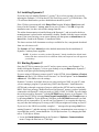
2.4 Installing Dynamic C
If you have not yet installed Dynamic C version 7.30 (or a later version), do so now by
inserting the Dynamic C CD from the OP7200 Tool Kit in your PC’s CD-ROM drive. The
CD will auto-install unless you have disabled auto-install on your PC.
If the CD does not auto-install, click Start > Run from the Windows Start button and
browse for the Dynamic C setup.exe file on your CD drive. Click OK to begin the
installation once you have selected the setup.exe file.
The online documentation is installed along with Dynamic C, and an icon for the documentation menu is placed on the workstation’s desktop. Double-click this icon to reach the
menu. If the icon is missing, create a new desktop icon that points to default.htm in the
docs folder, found in the Dynamic C installation folder.
The latest versions of all documents are always available for free, unregistered download
from our web sites as well.
The Dynamic C User’s Manual provides detailed instructions for the installation of
Dynamic C and any future upgrades.
NOTE: If you have an earlier version of Dynamic C already installed, the default installation of the later version will be in a different folder, and a separate icon will appear on
your desktop.
2.5 Starting Dynamic C
Once the OP7200 is connected to your PC and to a power source, start Dynamic C by
double-clicking the Dynamic C icon on your desktop or in your Start menu. Dynamic C
uses the serial port specified during installation
If you are using a USB port to connect your PC to the OP7200, choose Options > Project
Options and check “Use USB to Serial Converter” in “Serial Options” on the Communications tab. Click OK to save the settings.
Dynamic C assumes, by default, that you are using serial port COM1 on your PC when
you are running a program. If you are using COM1, then Dynamic C should detect the
OP7200 and go through a sequence of steps to cold-boot the OP7200 and to compile the
BIOS. If the error message “Rabbit Processor Not Detected” appears, you have probably
connected to a different PC serial port such as COM2, COM3, or COM4. You can change
the serial port used by Dynamic C with the OPTIONS menu, then try to get Dynamic C to
recognize the OP7200 by selecting Reset Target/Compile BIOS on the Compile menu or
by pressing <Ctrl-Y>. Try the different COM ports in the OPTIONS menu until you find
the one you are connected to. If you still can’t get Dynamic C to recognize the target on
any port, then the hookup may be wrong or the COM port might not working on your PC.
If you receive the “BIOS successfully compiled …” message after pressing <Ctrl-Y> or
starting Dynamic C, and this message is followed by a communications error message, it
is possible that your PC cannot handle the 115,200 bps baud rate. Try changing the baud
rate to 57,600 bps as follows.
• Locate the Serial Options dialog in the Dynamic C Options > Communications
menu. Change the baud rate to 57,600 bps.
User’s Manual
13
2.6 PONG.C
You are now ready to test your set-up by running a sample program.
Find the file PONG.C, which is in the Dynamic C SAMPLES folder. To run the program,
open it with the File menu (if it is not still open), then compile and run it by pressing F9 or
by selecting Run in the Run menu. The STDIO window will open on the PC and will display a small square bouncing around in a box.
This program shows that the CPU is working. The sample program described in
Section 5.2.3, “Run the PINGME.C Demo,” tests the TCP/IP portion of the board.
2.7 Where Do I Go From Here?
NOTE: If you purchased your OP7200 through a distributor or Rabbit partner, contact
the distributor or partner first for technical support.
If there are any problems at this point:
• Use the Dynamic C Help menu to get further assistance with Dynamic C.
• Check the Rabbit Technical Bulletin Board and forums at www.rabbit.com/support/bb/
and at www.rabbit.com/forums/.
• Use the Technical Support e-mail form at www.rabbit.com/support/.
If the sample program ran fine, you are now ready to go on to explore other OP7200 features and develop your own applications.
The following sample programs illustrate the features and operation of the OP7200.
Basic
BUFFLOCK.C
CONTRAST.C
PRIMITIVES.C
SCROLLING.C
TEXT.C
Keypad
KP_16KEY.LIB
KP_ANALOG.C
KP_BASIC.C
KP_MENU.C
Touchscreen
BTN_16KEY.C
BTN_BASICS.C
BTN_KEYBOARD.C
CAL_TOUCHSCREEN.C
RD_TOUCHSCREEN.C
These sample programs can be used as templates for applications you may wish to
develop.
Chapter 3, “Subsystems,” provides a description of the OP7200’s features, Chapter 4,
“Software,” describes the Dynamic C software libraries and introduces some sample programs. Chapter 5, “Using the TCP/IP Features,” explains the TCP/IP features.
14
eDisplay (OP7200)
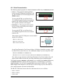
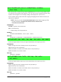
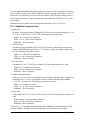
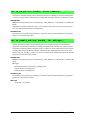
2.8 Remove Battery Tab
The backup battery on the OP7200 has a plastic tab to protect the battery against discharging before the OP7200 is placed into service. Although the battery is located inside the
OP7200’s protective casing, it is possible to reach the plastic tab using pliers or tweezers
from the opening on the side of the OP7200 shown in Figure 4.
USR
J3
D3
R23
OUT6
D2
OUT5
D5
OUT3
D4
OUT2
D6
OUT1
D8
OUT0
D9
+K
C29
PW
R
C86
R65
+PW
R
D20
TVS1
GN
D
+485
R14
9
485
RXD
GND
EGND
R-Net
RXC
TXC
R71
R72
R59
R60
R66
DS1
LNK
IN10
IN13
DS2
TXD
1
C40
/RST
Q31
IN15
C29 GND
JP6
IN14
ACT
JP5
Y3
C84
R36
R169
C30
JP2
JP1
E-Net
OUT7
R24
R38
R62
R16
D23
C85
R165
R164
R162
LNK
JP9
C14
C7
R15
R15 1
2
JP3
JP4
R21 R22
R90
U8 U7
J16
C25
JP3
IN9
C13
C1
J8
U3
C2
Fla
EPRsh
OM
R78R41
R85
R88 R89
J2
R86
D11
Y2
C49
J10
D24
D1
RT1
R87
R84
R83
R82
U2
L9
R79
C27 R38
R77
R76
R75
R74
C36
IN5
R11
R13
IN4
IN8
Q5
C16
C30
C13
C82
R81
R39
C3
JP2
IN3
J9
R18
C48
Q4
C18
C17
R37
R45
JP7
J2
J6
IN2
R36
D3
C43
IN7
Q3
Q11
R56 R64
R43
AGN
D
IN1
R8
R37
R15
C12
R17
R20
Q6
SLAVE
Q13
C39
U6
Y1 C4
R1 C17
C44
R19
Q7
2
4
Q10
D10
D2
R7
R14
C7
C8
C6
R55
R14
7
R40
R42
LS1
MSTR
1
R39
C66
JP6
J7
PROG
R2
D1
R22
C57
JP8
C65
R10
8
JP5
AIN
3
R27
R30
AIN
2
JP10
3
C28
Q2
C60
C33
C2 JP4
Q8
1
J14
1
C31
C8
U1
C61
C4
AIN
1
R19
R26
AIN
0
AIN
5
AIN
7
L2
DS2
JP1
C1
R18
R
R15 17
R16
IN18
AIN
4
AIN
6
IN0
IN6
BT1
Q3
C32
J1
J6
Y1
R159
R80
R9
Q4
Battery
R46
R91
Q2
60
Q12
R41
R44
J3
U2
R61
R25
R28
1
1
D15
C5
R2
R1
IN16
IN17
R20
R29
R31
D14
D12
J13
GN
D
Q5
D13
OUT4
1
J2
PWR
CAUTION: Disconnect power
before making or removing
terminal connections.
DS1
Pull
Plastic
Tab
ACT
C50
C51
J10
IN12
IN11
J12
J15
Figure 4. Remove Battery Tab
NOTE: Rabbit recommends that the battery tab not be removed until you are ready to
place the OP7200 in normal service with regular power connected to header J3.
The backup battery protects the contents of the SRAM and keeps the real-time clock
running when regular power to the OP7200 is interrupted. If you plan to use the real-time
clock functionality in your application, you will need to set the real-time clock once you
remove the plastic tab. Set the real-time clock using the onscreen prompts in the demonstration program. Alternatively, you may set the real-time clock using the SETRTCKB.C
sample program from the Dynamic C SAMPLES\RTCLOCK folder. The RTC_TEST.C
sample program in the Dynamic C SAMPLES\RTCLOCK folder provides additional examples of how to read and set the real-time clock.
User’s Manual
15
16
eDisplay (OP7200)
3. SUBSYSTEMS
Chapter 3 describes the principal subsystems for the OP7200.
• Digital I/O
• Analog Features (OP7200 only)
• Serial Communication
• Memory
• Liquid Crystal Display Controller
• Keypad
• OP7200 CPLD
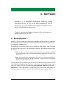
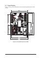
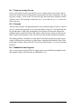
Figure 5 shows these Rabbit-based subsystems designed into the OP7200.
32 kHz 11 MHz
osc
osc
SRAM
Flash
RABBIT
2000
RS-232
RS-485
CPLD
Digital
Input
Digital
Output
A/D
Converter
Ethernet
RabbitCore Module
Touchscreen
Controller
Interface to
LCD/Keypad
Figure 5. OP7200 Subsystems
The memory and microprocessor are located on the RabbitCore module. The RCM2200
module is used on the OP7200. If you have more than one OP7200 or other Rabbit products
built around RabbitCore modules, take care not to swap the RabbitCore modules since they
contain system ID block information and calibration constants that are unique to the board
they were originally installed on. It is a good idea to save the calibration constants should
you need to replace a RabbitCore module in the future. See Section 4.3.8, “Using System
Information from the RabbitCore Module,” for more information.
User’s Manual
17
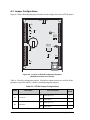
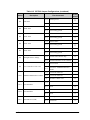
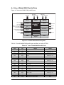
3.1 OP7200 Pinouts
The OP7200 pinouts are shown in Figure 6.
Digital
Inputs
Analog
Inputs
IN16
J3
J2
OUT7
IN18
OUT6
AIN0
OUT5
AIN1
OUT4
AIN2
OUT3
AIN3
OUT2
AIN4
OUT1
AIN5
OUT0
Battery
AIN6
AIN7
+K
-PWR
AGND
IN0
+PWR
J6
J10
+485
IN2
485
C3
D2
R7
RXC
RS-485
RS-232
TXC
/RST
U2
J2
C30
JP2
JP1
R15
C12
R17
R18
R19
C13
C14
R16
JP6
DS2
DS1
Q5
R21 R22
Y3
LNK
Q4
R20
IN14
C29 GND
JP5
C28
Q3
Power
Supply
Reset
IN15
U1
Q2
K
RXD/CTS
C7
IN13
GND
Digital
Inputs
IN12
C25
IN11
JP3
JP4
IN10
U8 U7
C1
TXD/RTS
RT1
D3
R11
BT1
U3
D1
R37
C8
IN8
IN9
R36
Y2 C2
R41
R9
R13
IN7
R8
R38
Y1 C4
R1 C17
C27
U6
IN5
IN6
R39
R2
Flash
EPROM
J1
IN4
Digital
Outputs
GND
IN1
IN3
Digital
Inputs
GND
IN17
EGND
ACT
Ethernet
RabbitNet
Figure 6. OP7200 Pinouts
NOTE: Screw-terminal header J2 and the associated analog and digital I/O are not available on the OP7210.
3.1.1 Headers and Screw Terminals
Standard OP7200 models are equipped with four 1 × 12 screw terminal strips (J2, J3, J6,
and J10), and a 2 × 5 programming header and an RJ-45 Ethernet jack on the RCM2200
RabbitCore module.
The RJ-45 jack labeled RabbitNet is a serial I/O expansion port for use with RabbitNet
I/O cards. The RabbitNet jack does not support Ethernet connections. Be careful to connect
your Ethernet cable to the jack labeled Ethernet.
18
eDisplay (OP7200)
3.2 Indicators
3.2.1 LEDs
The OP7200 has two LEDs, Power Good and Microprocessor Bad.
The green Power Good LED at DS2 indicates when power is applied to the OP7200 and
that Vcc is within the proper operating range of 4.5 to 5.5 V. The LED turns off when the
OP7200 is being reset.
The red Microprocessor Bad LED at DS1 indicates the status of the OP7200. Following
reset, DS1 will be ON and will remain ON until turned OFF by Dynamic C. Once the
microprocessor comes out of reset and finishes all its internal checks and initializes the
system, it should turn DS1 OFF.
The operation of DS1 may be redefined in any manner desired with the caveat that DS1
comes ON after reset. The USR label on the dust cover refers to the LED at DS1 and
reflects its secondary purpose as a user-defined indicator.
3.2.2 Buzzer
An audible buzzer is turned on and off through the use of a programmed I/O bit defined in
software.
User’s Manual
19
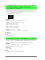
3.3 Digital I/O
3.3.1 Digital Inputs
The OP7200 has 19 digital inputs, IN0–IN18, each of which is protected over a range of
–36 V to +36 V. The inputs are factory-configured to be pulled up to +5 V, but they can
also be pulled down to 0 V in banks of eight by changing a surface-mounted 0 Ω resistor.
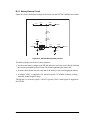
Figure 7 shows a sample digital input circuit. All 19 inputs are protected against noise
spikes by a low-pass filter composed of a 22 kΩ series resistor and a 10 nF capacitor.
JP3
0W
Vcc
Factory
Default
27 kW
22 kW
10 nF
Rabbit 2000®
Microprocessor
GND
Figure 7. OP7200 Digital Inputs [Pulled Up—Factory Default]
OP7200 series boards can be made to order in volume with the banks of digital inputs
pulled down to 0 V. Contact your authorized Rabbit distributor or your Rabbit sales
representative for more information.
For IN0–IN7 the actual switching point between a zero and a one is 1.5 V max and 3.5 V
min respectively. The range between 1.5 and 3.5 V is undefined. For IN8–IN15 the actual
switching point between a zero and a one is 0.8 V max and 2.0 V min respectively. The
range between 0.8 and 2.0 V is undefined. For IN16–IN17, which are available only on
the OP7200 model, the actual switching point between a zero and a one is 0.8 V max and
3.5 V min respectively. The range between 0.8 V and 3.5 V is undefined.
Therefore, the input voltage must be less than 0.8 V for all the digital inputs as a group to
ensure that a zero is being read, and the input voltage must be must be greater than 3.5 V
for a one.
IN16–IN18 interface to the A/D converter chip serially with an access time of 100 µs,
which is different from the access time of 5 µs for IN0–IN15, which interface in parallel
with the Rabbit 2000 microprocessor.
20
eDisplay (OP7200)
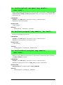
The digital inputs are each fully protected over a range of -36 V to +36 V, and can handle
short spikes of ±40 V.
Normal Switching
Levels
Digital Input Voltage
+40 V
+36 V
Spikes
Spikes
+3.3 V
40 V
Spikes
Figure 8. OP7200 Digital Input Protected Range
User’s Manual
21
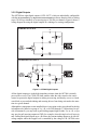
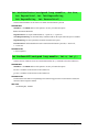
3.3.2 Digital Outputs
The OP7200 has eight digital outputs, OUT0–OUT7, which are individually configurable
with the digoutConfig or digoutTriStateConfig software function calls as sinking
(up to 350 mA per channel) or as sourcing (up to 250 mA per channel). Figure 9 shows a
wiring diagram for using the digital outputs in a sinking or a souring configuration.
SINKING OUTPUTS
+K
Current
Flow
CPLD
SINK
CONTROL
SIGNAL
SOURCING OUTPUTS
+K
CPLD
SOURCE
CONTROL
SIGNAL
Current
Flow
Figure 9. OP7200 Digital Outputs
All the digital outputs are in the high-impedance tristate when the OP7200 is initially
powered on or reset. The CPLD (U4) then enables either the sink control or the source
control to operate the digital outputs as sinking or sourcing, and thereby serves as a hardware block to prevent both sinking and sourcing drivers from being activated at the same
time in a given channel.
Although the components are not installed, there is provision on the circuit board for the digital outputs to be pulled as a group to Vcc, +K, or to GND through 27 kΩ resistors. In special circumstances, you may need to pull sinking outputs high to either Vcc or +K, or you
may need to pull sourcing outputs to GND, for example, when driving low-level logic signals. Pulling the digital outputs up to +K allows the current-sinking outputs to be used as
voltage outputs where their upper level is controlled by the voltage of +K. OP7200 series
22
eDisplay (OP7200)
boards can be made to order in volume with the digital outputs pulled up to Vcc or +K, or
pulled down to GND. Contact your authorized Rabbit distributor or your Rabbit sales representative for more information.
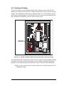
+K is an externally supplied voltage of 9–40 V DC used primarily in combination with
current sourcing outputs, and should be capable of delivering up to 2 A. Although a connection to a +K supply is not absolutely required with sinking outputs, it is highly recommended to protect against current spikes when driving inductive loads.
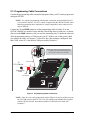
Connect the positive +K supply to pin 3 of screw-terminal header J3 and the negative side
of the supply to pin 12 of screw-terminal header J3. Exercise care to connect this supply
correctly because the +K inputs are not protected against reverse polarity, and serious
damage to the OP7200 may result if you connect this supply backwards.
When you are using the same DC power supply as the main power supply for the OP7200
and as the +K power supply, Rabbit recommends that you tie the -PWR connection to
ground. Since this step will bypass the reverse-polarity protection afforded by the fullwave bridge rectifier, ensure that the positive leads from the power supply are connected
correctly to prevent damage to the OP7200.
Tie -PWR to GND
if using same
power supply for
OP7200 and +K
PWR
J3
USR
GND
IN16
1
OUT7
IN17
OUT6
IN18
Load
OUT5
AIN0
OUT4
OUT3
AIN2
AIN3
OUT1
AIN4
J3
Load
OUT0
AIN5
+K
AIN6
AGND
PWR
+PWR
AIN7
+
1
J2
D23
J6
Connected to
Sinking
Output
-PWR
AC
Adapter
GND
485
GND
IN4
IN5
OUT2
RXD
Load
Connected to
Sinking
Output
IN11
LNK
IN13
ACT 1
+K
6
3
IN12
IN10
Connected to
Sourcing
Output
J10
IN9
IN14
IN8
IN15
IN7
/RST
IN6
Load
TXD
9
RXC
IN3
J10
PROG
OUT5
12
TXC
IN2
J1
IN1
1
+
+PWR
D20
+485
IN0
1
J6
External
+K Power
Supply
OUT2
AIN1
CAUTION: Disconnect power
before making or removing
terminal connections.
J2
Connected to
Sourcing
Output
J15
E-Net
R-Net
Figure 10. +K, Power Supply, and Sample Load Connections
User’s Manual
23
3.4 Analog Features (OP7200 only)
The single A/D converter used in the OP7200 (the OP7210 does not have analog or touchscreen capabilities) has a resolution of 11 bits (single-ended mode) or 12 bits (differential
mode). There are eight channels of A/D conversion, and the OP7200 also has provision
for up to four digital inputs. Three of the four digital inputs are available on screw terminal
header J2. The fourth digital input serves as a board status bit, and is controlled by a 0 Ω
surface-mount resistor R159. The factory default is for R159 to not be installed, which
leaves this fourth input pulled up to Vcc.
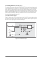
3.4.1 A/D Converter Inputs
Figure 11 shows a pair of A/D converter input circuits. Each A/D converter input consists
of resistors and a capacitor. The resistors form a10:1 attenuator, and the capacitor protects
the A/D converter input against electrostatic discharges.
+V
AIN0
180 kW
ADC
ADC
AIN1
20 kW
1 nF 1 nF
20 kW
180 kW
2.048 V
0W
AGND
Factory
Default
Figure 11. A/D Converter Inputs
24
eDisplay (OP7200)
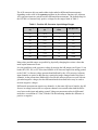
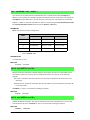
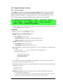
The A/D converter chip can make either single-ended or differential measurements
depending on the value of the opmode parameter in the software function call. Adjacent
A/D converter inputs are paired to make differential measurements. The default setup for
the OP7200 is to measure only positive voltages for the ranges listed in Table 2.
Table 2. Positive A/D Converter Input Voltage Ranges
Min. Voltage
(V)
Max. Voltage
(V)
Amplifier
0.0
+20.0
1
10
0.0
+10.0
2
5
0.0
+5.0
4
2.5
0.0
+4.0
5
2.0
0.0
+2.5
8
1.25
0.0
+2.0
10
1.0
0.0
+1.25
16
0.625
0.0
+1.0
20
0.500
Gain
mV per Tick
Many other possible ranges are possible by physically changing the resistor values that
make up the attenuator circuit.
It is also possible to read a negative voltage by moving the 0 Ω jumper (see Figure 11) on
header JP4, JP5, JP6, or JP7 associated with the A/D converter input from analog ground
to the 2.048 V reference voltage generated and buffered by the A/D converter. Adjacent
input channels are paired so that moving a particular jumper changes both of the paired
channels. At the present time Rabbit does not offer the software drivers to work with single-ended negative voltages, but the differential mode described below may be used to
measure negative voltages.
Differential measurements require two channels. As the name differential implies, the difference in voltage between the two adjacent channels is measured rather than the difference between the input and analog ground. Voltage measurements taken in differential
mode have a resolution of 12 bits, with the 12th bit indicating whether the difference is
positive or negative.
User’s Manual
25
The A/D converter chip can only accept positive voltages. When the 0 Ω resistor shown in
Figure 11 ties the A/D attenuator circuit to analog ground, both differential inputs must be referenced to analog ground, and both inputs must be positive with respect to analog ground.
If a device such as a battery is connected across two channels for a
differential measurement, and it is
not referenced to analog ground,
then the current from the device
will flow through both sets of
attenuator resistors as shown in
Figure 12. This will generate a
negative voltage at one of the
inputs, AIN1, which will almost
certainly lead to inaccurate A/D
conversions.
180 kW
AIN0
Device +
AIN1
0
1 nF
I
ADC
20 kW
+
1 nF
180 kW
20 kW
1
Figure 12. Current Flow from Ungrounded
or Floating Source
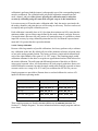
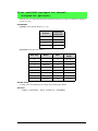
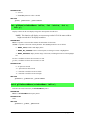
To make such differential measurements, move the 0 Ω resistor jumper (see Figure 11)
associated with the A/D converter inputs (JP4, JP5, JP6, or JP7) from analog ground to the
2.048 V reference voltage. This allows input voltages that are negative with respect to
analog ground. Table 3 provides the differential voltage ranges for this setup.
Table 3. Differential Voltage Ranges
26
Min. Differential
Voltage
(V)
Max. Differential
Voltage
(V)
Amplifier
0
±20.0
×1
10
0
±10.0
×2
5
0
±5.0
×4
2.5
0
±4.0
×5
2.0
0
±2.5
×8
1.25
0
±2.0
×10
1.00
0
±1.25
×16
0.625
0
±1.0
×20
0.500
Gain
mV per Tick
eDisplay (OP7200)
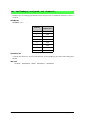
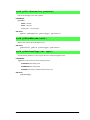
The input circuit of the OP7200 was designed to use the differential mode in a unique way
to support measuring voltages in an equal range above and below ground. This method
also requires you to move the 0 Ω jumper (see Figure 11) on the header associated with the
A/D converter inputs (JP4, JP5, JP6, or JP7) from analog ground to the 2.048 V reference
voltage. The input is connected to the even-numbered channel, and the odd-numbered
channel is tied to analog ground. Table 4 provides the bipolar voltage ranges for this setup.
Table 4. Bipolar Voltages
Min. Voltage
(V)
Max. Voltage
(V)
Amplifier
-20.0
+20.0
1
10
-10.0
+10.0
2
5
-5.0
+5.0
4
2.5
-4.0
+4.0
5
2.0
-2.5
+2.5
8
1.25
-2.0
+2.0
10
1.00
-1.25
+1.25
16
0.625
-1.0
+1.0
20
0.500
Gain
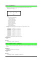
mV per Tick
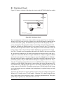
3.4.2 Analog Current Measurements
The A/D converter inputs can also be used with 4–20 mA
current sources by measuring the resulting analog voltage drop across a 100 Ω 1% precision resistor placed
between the analog input and analog ground as shown in
Figure 13.
AIN0AIN7
100 W
1%
AGND
The single-ended scale of 0–2.56 V with a gain of 8 is
used to get an A/D current conversion of 12.5 µA/tick. Figure 13. Resistor for 4–20 mA
Current Sources
User’s Manual
27
3.4.3 Calibrating the A/D Converter Chip
Manufacturing tolerances for resistors, bias currents, offset voltages, gain, and the like
introduce errors into the A/D conversions. Ideally there would be a one-to-one straightline relationship between the input voltage and the output of the A/D converter, and a
graph of such a line would have a slope of 1 and would pass through the (0,0) coordinate.
However, the errors arising from manufacturing tolerances introduce a deviation between
the applied input voltage and the voltage that is output by the A/D converter. The actual
plot of voltage in vs. the voltage out from A/D converter is not actually a straight line.
However, a straight line is a very good first-order approximation, and the calibration routines provided for the OP7200 are based on a straight line with a slope of 1 and an offset
from (0,0). The calibration routines use two known measurement points on the voltage-in
vs. voltage-out line as the basis to calculate calibration constants that will be used to adjust
for the slope of the line and the offset from (0,0). The calibration routines typically use
input voltage points that are 10% less then the maximum and 10% more than the minimum readings possible for the A/D converter on any given range.
Quality calibration procedures are extremely important in obtaining good A/D converter
results. No matter how high a resolution the A/D converter has, it cannot compensate for
improper calibration. A/D converter results will never be more accurate than the meter
used in the calibration process. Therefore, use the best digital volt and milli-amp meter
available that meets or exceeds the accuracy of the A/D converter chip.
3.4.3.1 Modes
The OP7200 A/D converter operates in three different modes:
• the single-ended mode,
• the differential mode, and
• the milli-amp mode
The calibration and read routines provided correspond to these three modes.
3.4.3.2 Calibration Constants
The A/D converter has eight individual input channels, and each channel has eight programmable gains. Additionally, the A/D converter has the capability for adjacent inputs
to be paired to make differential measurements with eight different gains, and provision is
also made to convert 4–20 mA analog current measurements.
28
eDisplay (OP7200)
To get the best results form the A/D converter, it is necessary to calibrate each mode for
each of its gains. The following table provides a grid for each possible set of calibration
constants.
Mode
Single-Ended
Gain
Code
1
2
4
5
8
10
mA
16
20
4
Differential
1
2
4
5
8
10
16
20
0
1
Input
2
3
4
5
6
7
For the single-ended mode there are calibration constants for each channel and for each of
its gains, for a total of 64 sets of calibration constants. The milli-amp mode covers 4–20 mA
(actually 0–25 mA) currents. Separate calibration and read-back routines are provided for
this. Since only one range of current measurement is provided, these routines use only one
gain (4). One set of calibration constants is provided for each of the eight input channels.
The differential-mode routines use a pair of input channels to make measurements. In this
case, calibration constants are stored for each pair of channels and for each of the eight
gains, for a total of 32 sets of calibration constants.
When a calibration is performed, it fills in one of the squares in the table with a set of calibration constants representing the corresponding mode, channel, and gain. These constants are stored in flash memory, and are thus maintained even when power is been
removed from the OP7200. Note that calibration constants are stored for each of the
modes. Since A/D converter read routines select the appropriate calibration constants based
on the mode, it is possible for software calls to move from one mode to another without
recalibration.
3.4.3.3 Calibration Recommendations
It is imperative that you calibrate each of the A/D converter inputs in the same manner as
they are to be used in the application. For example, if you will be performing floating differential measurements or differential measurements using a common analog ground, then
calibrate the A/D converter in the corresponding manner. The calibration must be done
with the attenuator reference selection jumper in the desired position (see Figure 11). If a
User’s Manual
29
calibration is performed and the jumper is subsequently moved, the corresponding input(s)
must be recalibrated. The calibration table only holds calibration constants based on
mode, channel, and gain. Other factors affecting the calibration must be taken into
account by calibrating using the same mode and gain setup as in the intended use.
It is not necessary to fill out the entire calibration table. Only the entries associated with
the modes, channels, and gains that you will be using are necessary. This fact can be used
to simplify and speed up the calibration process.
Each calibration is normally done at 10% less than the maximum and 10% more than the
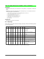
minimum within a given voltage range defined by the mode, channel, and gain. However,
if an application is known to use only portion of a particular range, it is possible to obtain
improved accuracy by using calibration points that are 10% less than the expected maximum and 10% greater than the expected minimum.
3.4.3.4 Factory Calibration
Because of the large number of possible calibrations, the factory performs only a rudimentary calibration on the unit. By default, all four of the attenuator reference selection jumpers are in the analog ground position. The factory performs a single-ended calibration on
each of the eight channels with a gain of 1 (0–20 V range). The remaining single-ended
calibration constants for the other seven gains are approximated and are filled in based on
the initial calibration. The milli-amp and differential portions of the table are filled in
using typical expected values. All read routines will work properly with these factory-initialized calibration constants, but only the single-ended mode should be expected to return
accurate results over a range of 0–20 V until you recalibrate the OP7200 for your use.
Sample programs are provided to illustrate how to read and calibrate the various A/D
inputs for the three operating modes.
Mode
Read
Calibrate
Single-Ended, one channel
ADRD_SE_CH.C
ADCAL_SE_CH.C
Single-Ended, all channels
ADRD_SE_ALL.C
ADCAL_SE_ALL.C
Milli-Amp
ADRD_MA_CH.C
ADCAL_MA_CH.C
Differential, analog ground
ADRD_DIFF_GND.C
ADCAL_DIFF_GND.C
Differential, 2 V reference
ADRD_DIFF_2V.C
ADCAL_DIFF_2V.C
These sample programs are found in the ADC subdirectory in SAMPLES\OP7200. See
Section 4.3, “Sample Programs,” for more information on these sample programs and how
to use them.
30
eDisplay (OP7200)
3.4.4 Touchscreen
The OP7200 analog touchscreen provides a high-resolution matrix of 4096 × 4096
elements. The touchscreen is mounted to the front of and is the same size as the LCD module. A four-conductor flex cable connects the touchscreen to the OP7200 at connector J13.
The inputs from the touchscreen are protected from ESD by ferrite beads, capacitors, and
shunt diodes. The ferrite beads and capacitors also serve to eliminate EMI radiating from
the cable. Ferrite beads rather than resistors are used in series with the inputs to maintain
the most accurate measurement of the touchscreen x,y position.
A reference voltage is applied across the touchscreen. When the touchscreen is touched,
resistances that represent the x,y position are presented at the input circuit. The touchscreen
controller chip U9 converts these resistances into digital form for use by the software.
NOTE: Should you touch two or more different points on the touchscreen simultaneously,
the resistance presented to the input circuit will represent some difference between the
resistances corresponding to the points. This can lead to a different or an unknown
key’s value being processed. To prevent this from happening, exercise care to “touch”
only one point or position on the touchscreen at a time.
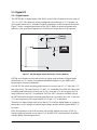
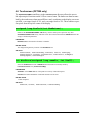
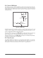
3.4.5 Analog Supply Voltage
The analog section is isolated from digital noise generated by other components by way of a
low-pass filter composed of L2, C31, and C32 as shown in the left side of Figure 14. The +V
analog power supply powers the A/D converter chip.
+V
Vcc
+V
ADC Chip
Internal
Reference
Voltage
L2
C31
100 nF
C32
100 nF
1 2 3
JP8
To
A/D Converter
R148
100 W
R150
453 W
U12
C91
100 nF
Figure 14. Analog Supply and Voltage Reference Circuits
User’s Manual
31
3.4.6 A/D Converter Reference Voltage (+V)
A reference voltage of 2.048 V is generated by the A/D converter chip. The reference voltage is used by the touchscreen controller chip, and may also be used to bias the input
attenuator circuits when bipolar inputs are to be measured. As shown in Figure 14, the
factory default is for a surface-mounted 0 Ω resistor to connect pins 1–2 on header JP8.
This enables the internal reference voltage of 2.048 V generated by the A/D converter chip.
By connecting pins 2–3 on header JP8 instead, a ratiometric reference can be provided by
the divider consisting of R148 and R150. A fixed reference can be configured by removing R150 and installing a zener diode at U12. The zener diode will then set the reference
voltage. C91 would be always installed, and provides filtering. None of these components
(R148, R150, C91, or U12) is factory-installed.
32
eDisplay (OP7200)
3.5 Serial Communication
The OP7200 has two RS-232 serial ports, which can be configured as one RS-232 serial
channel (with RTS/CTS) or as two RS-232 (3-wire) channels using the serMode software
function call. Table 5 summarizes the options.
Table 5. Serial Communication Configurations
Serial Port
Software
Mode
*
B
C
D
0
RS-485
RS-232, 3-wire
RS-232, 3-wire
1
RS-485
RS-232, 5-wire
CTS/RTS
2
not initialized*
RS-232, 3-wire
RS-232, 3-wire
3
not initialized*
RS-232, 5-wire
CTS/RTS
Use modes 2 and 3 when Serial Port B is going to used by other libraries such as
PACKET.LIB.
The OP7200 also has one RS-485 serial channel and a CMOS serial channel that serves as
the programming port. When you are using the OP7200 in a RabbitNet network, Serial
Port B is configured as a clocked serial port and the RS-485 chip drives the RabbitNet
port—the OP7200 then cannot be used for RS-485 serial communication.
All four serial ports operate in an asynchronous mode up to the baud rate of the system
clock divided by 32. An asynchronous port can handle 7 or 8 data bits. A 9th bit address
scheme, where an additional bit is sent to mark the first byte of a message, is also supported. Serial Port A, the programming port, and Serial Port B can be operated alternately
in the clocked serial mode. In this mode, a clock line synchronously clocks the data in or
out. Either of the two communicating devices can supply the clock. When the Rabbit provides the clock, the baud rate can be up to ¼ of the system clock frequency, or more than
5.525 Mbps for a 22.1 MHz clock speed.
The OP7200 boards use all four serial ports. Serial Port A is used in the clocked serial
mode to provide cold-boot, download, and emulation functions. Serial Port B is used
either for RS-485 or for RabbitNet communication, and Serial Ports C and D are used for
RS-232 communication. The OP7200 uses an 11.0592 MHz crystal, which is doubled to
22.1184 MHz. At this frequency, the OP7200 supports standard asynchronous baud rates
up to a maximum of 230,400 bps.
User’s Manual
33
3.5.1 RS-232
The OP7200 RS-232 serial communication is supported by an RS-232 transceiver. This
transceiver provides the voltage output, slew rate, and input voltage immunity required to
meet the RS-232 serial communication protocol. Basically, the chip translates the Rabbit
2000’s CMOS/TTL signals to RS-232 signal levels. Note that the polarity is reversed in an
RS-232 circuit so that a +5 V output becomes approximately -10 V and 0 V is output as
+10 V. The RS-232 transceiver also provides the proper line loading for reliable communication.
RS-232 can be used effectively at the OP7200’s maximum baud rate for distances of up to
15 m.
If you are planning to use any of the RS-232 serial ports and the RabbitNet port on the
OP7200, initialize the serial port(s) before you initialize the RabbitNet port. Section 4.5.4
provides some sample code to illustrates the sequence.
3.5.2 RS-485
The OP7200 has one RS-485 serial channel, which is connected to the Rabbit 2000 Serial
Port B through an RS-485 transceiver. The half-duplex communication uses an output
from the CPLD (U4) to control the transmit enable on the communication line. Using this
scheme a strict master/slave relationship must exist between devices to insure that no two
devices attempt to drive the bus simultaneously.
GND
RS485+
RS-485
GND
RS485+
RS-485
GND
RS485+
RS-485
The OP7200 can be used in an RS-485 multidrop network spanning up to 1200 m (4000 ft),
and there can be as many as 32 attached devices. Connect the 485+ to 485+ and 485– to
485– using single twisted-pair wires as shown in Figure 15. Note that a common ground is
recommended.
Figure 15. OP7200 Multidrop Network
34
eDisplay (OP7200)
The OP7200 comes with a 220 Ω termination resistor and two 681 Ω bias resistors
installed and enabled with jumpers across pins 1–2 and 4–6 on header J8, as shown in
Figure 16.
C18
C17
OUT3
D4
Q6
OUT1
D9
Q10
OUT0
R55
+K
R65
R64
R62
R45
AIN7
C29 C86
R56
R43
AIN6
Q13
PWR
R147
C16
C30
D8
JP6
Q11
OUT2
D6
4
SLAVE
OUT6
D5
OUT5
D2
C8
C6
R39
C66
3
GND
D3
Q8
R37
2
C7
OUT7
R14
R38
1
LS1
Battery
R46
R22
JP5
AIN5
R69
681 W
bias
J7
Q3
Q7
MSTR
JP10
Q12
R41
R44
R68
220 W
J14
485
R40 R42
AIN4
R29
R31
Q4
R23
C57
6
C65
R159
JP8
R108
AIN3
R27 R30
AIN2
R25
R28
termination
D1
Q2
R24
R61
C60
JP4
AIN1
R19 R26
AIN0
Y1
R91
60
J3
C5
C33
1
4
C61
2
C2
R16
R17
C4
R15
IN18
R18
J8
U2
R70
681 W
bias
DS2
1
D15
JP1
C1
C13
AGND
+PWR
C32
U2
R90
J2
C30
JP2
R16
DS2
DS1
Y3
LNK
Q5
C50
R20
C51
Q4
J12
C14
JP6
+485
GND
C25
IN11
R19
R21 R22
485
RXD
C29 GND
JP5
IN12
IN10
Q3
R18
C13
R71
R72
R59
R60
R66
JP1
C12
R17
Q2
TXC
C40
C28
5
IN13
JP3
IN9
U1
3
RXC
Q31
R36
R169
C48
R15
1
TXD
C7
IN8
BT1
6
/RST
JP3
JP4
R11
R13
IN7
D3
4
IN15
R89
R86
U8 U7
C1
2
IN14
R162
RT1
Flash
EPROM
R41
R84
R37
R149
R165
R164
R88
R38
R87
R36
R85
R83
R82
IN6
C44
C27
IN5
C8
R8
J9
C84
D1
C3
IN4
R9
Y1 C4
R1 C17
U3
JP9
R39
IN3
U6
C43
C85
R78
R79
R77
R76
R75
R74
C36
IN2
D2
R7
J16
Y2 C2
R2
R151
R152
JP2
IN1
D24
GND
J8
IN0
D11
D10
D20
J8
J6
L9
J1
D23
C82
R81
R80
EGND
J10
JP7
J2
C49
C39
L2 C31
Factory
Default
TVS1
IN17
6
7
R20
Q5
D14
J13
R2
R1
IN16
U6
D12
DS1
D13
OUT4
Vcc
485+
ACT
J15
Figure 16. RS-485 Termination and Bias Resistors
For best performance, the termination resistors in a multidrop network should be enabled
only on the end nodes of the network, but not on the intervening nodes. Jumpers on boards
whose termination resistors are not enabled may be stored across pins 1–3 and 5–6 of
header J8.
NOTE: Remove the back cover from the OP7200 to access the bias and termination
resistor jumpers on header J8.
User’s Manual
35
3.5.3 RabbitNet Port
The RJ-45 jack labeled RabbitNet is a serial I/O expansion port for use with RabbitNet
I/O cards. The RabbitNet jack does not support Ethernet connections. There is also no
provision for the OP7200 to supply power to any RabbitNet peripheral cards.
When you are using the OP7200 in a RabbitNet network, Serial Port B is configured as a
clocked serial port and the RS-485 chip drives the RabbitNet port—the OP7200 then
cannot be used for RS-485 serial communication.
If you are planning to use any of the RS-232 serial ports and the RabbitNet port on the
OP7200, initialize the serial port(s) before you initialize the RabbitNet port. Section 4.5.4
provides some sample code to illustrates the sequence.
In principle, the OP7200 can operate either as a master controller with RabbitNet expansion I/O, or it can operate as a slave operator interface in a RabbitNet network. Jumper
settings on header JP10 are used to configure the OP7200 for master or slave operation as
shown in Appendix A.3, “Jumper Configurations.” The factory default is for the OP7200
to be configured as a RabbitNet master.
At the present time, Dynamic C does not support the operation of the OP7200 as a slave,
and so the OP7200 is restricted to being used as a master.
Appendix D provides additional information about the RabbitNet system.
36
eDisplay (OP7200)
3.5.4 Ethernet Port
Figure 17 shows the pinout for the Ethernet port (J2 on the OP7200’s RabbitCore module).
Note that there are two standards for numbering the pins on this connector—the convention
used here, and numbering in reverse to that shown. Regardless of the numbering convention followed, the pin positions relative to the spring tab position (located at the bottom of
the RJ-45 jack in Figure 17) are always absolute, and the RJ-45 connector will work properly with off-the-shelf Ethernet cables.
ETHERNET
1
8
1.
2.
3.
6.
RJ-45 Plug
E_Tx+
E_Tx
E_Rx+
E_Rx
RJ-45 Jack
Figure 17. RJ-45 Ethernet Port Pinout
RJ-45 pinouts are sometimes numbered opposite to the way shown in Figure 17.
Two LEDs are placed next to the RJ-45 Ethernet jack, one to indicate a live Ethernet link
(LNK) and one to indicate Ethernet activity (ACT).
The transformer/connector assembly ground is connected to the OP7200’s RabbitCore
module printed circuit board digital ground via a 0 Ω resistor “jumper,” R29, as shown in
Figure 18.
RJ-45 Ethernet Plug
R29
Board
Ground
Chassis
Ground
Figure 18. Isolation Resistor R29
The factory default is for the 0 Ω resistor “jumper” at R29 to be installed. In high-noise
environments, remove R29 and ground the transformer/connector assembly directly
through the chassis ground by using the EGND terminal on the RabbitCore module. This
will be especially helpful to minimize ESD and/or EMI problems.
User’s Manual
37
3.5.5 Programming Port
The RabbitCore module on the OP7200 has a 10-pin programming header. The programming port uses the Rabbit 2000’s Serial Port A for communication. Dynamic C uses the
programming port to download and debug programs.
The programming port is also used for the following operations.
• Cold-boot the Rabbit 2000 on the RabbitCore module after a reset.
• Remotely download and debug a program over an Ethernet connection using the
RabbitLink EG2110.
• Fast copy designated portions of flash memory from one Rabbit-based board (the
master) to another (the slave) using the Rabbit Cloning Board.
Alternate Uses of the Serial Programming Port
All three clocked Serial Port A signals are available as
• a synchronous serial port
• an asynchronous serial port, with the clock line usable as a general CMOS input
The serial programming port may also be used as a serial port via the DIAG connector on
the serial programming cable.
In addition to Serial Port A, the Rabbit 2000 startup-mode (SMODE0, SMODE1), status,
and reset pins are available on the serial programming port.
The two startup mode pins determine what happens after a reset—the Rabbit 2000 is
either cold-booted or the program begins executing at address 0x0000.
The status pin is used by Dynamic C to determine whether a Rabbit microprocessor is
present. The status output has three different programmable functions:
1. It can be driven low on the first op code fetch cycle.
2. It can be driven low during an interrupt acknowledge cycle.
3. It can also serve as a general-purpose CMOS output.
The /RESET_IN pin is an external input that is used to reset the Rabbit 2000 and the
onboard peripheral circuits on the RabbitCore module. The serial programming port can be
used to force a hard reset on the RabbitCore module by asserting the /RESET_IN signal.
The green Power Good LED goes off momentarily during a reset.
Refer to the Rabbit 2000 Microprocessor User’s Manual for more information.
38
eDisplay (OP7200)
3.6 Memory
3.6.1 SRAM
The OP7200’s RabbitCore module is designed to accept 128K to 512K of SRAM packaged in an SOIC case. The standard OP7200’s RabbitCore modules come with 128K of
SRAM.
3.6.2 Flash Memory
The OP7200 is also designed to accept 128K to 512K of flash memory. The standard
OP7200’s RabbitCore modules comes with one 256K flash memory.
NOTE: Rabbit recommends that any customer applications should not be constrained by
the sector size of the flash memory since it may be necessary to change the sector size
in the future.
A Flash Memory Bank Select jumper configuration option based on 0 Ω surface-mounted
resistors exists at header JP2 on the RabbitCore module. This option, used in conjunction
with some configuration macros, allows Dynamic C to compile two different co-resident
programs for the upper and lower halves of the 256K program flash in such a way that
both programs start at logical address 0000. This is useful for applications that require a
resident download manager and a separate downloaded program. See Technical Note 218,
Implementing a Serial Download Manager for a 256K Flash, for details.
User’s Manual
39
3.7 Liquid Crystal Display Controller
The LCD module controller chip provides support for the LCD module. The controller
chip is attached to the data bus on the OP7200’s RabbitCore module, and is mapped to the
I/O address space. This interface is composed of eight data bits, one address line, and three
control lines (/IORD, /IOWR, and /LCDM-CS).
The interface from the LCD controller to the LCD module is unidirectional. Data flow from
the controller chip to the LCD module. A number of control lines are provided for this function, but not all of them are used for a particular LCD module. The controller continually
reads the SRAM (which is included on the LCD controller chip used after January,2006)
for data placed there by the microprocessor and refreshes the display periodically.
Other functions support the LCD module to adjust its contrast and to turn the white LED
backlight on and off. A variable resistor between two of the LCD module’s terminals sets
the contrast. U5 is a digitally controlled potentiometer that is controlled by software. Once
the value is set, the value will be maintained. A single programmed I/O bit is used to turn
the LED backlight on or off. Since this bit does not have enough drive current to light the
LED directly, it is buffered by the FET Q1.
The controller chip used in OP7200’s sold before 2006 supported either 32K or 64K of
SRAM. These OP7200s were designed using a dual-footprint SRAM to accept either one
32K or one 128K SRAM. The 128K part was standard. The full 64K supported by the
controller is available with the 128K SRAM, plus an additional 64K can be swapped in
and out by using the programmed I/O bit VA16. Pins 1–2 on header JP9 are normally connected by a 0 Ω surface-mounted resistor, but pins 2–3 should be connected instead for
video SRAM paging with I/O bit VA16.
OP7200 units sold after January, 2006, have a new LCD controller chip because the previously used LCD controller chip is no longer available. The new LCD controller chip has
32K of internal SRAM. Figure 19 shows the area of the OP7200 that changed to accommodate the new LCD controller chip. The new LCD controller is not 100% code-compatible
with the old chip—Section 4.1.2.1 explains how to handle programs developed using
versions of Dynamic C before v. 9.40.
PRE-2006 OP7200
DS2
DS1
GND
J3
OUT7
C7
OUT4
GND
OUT3
OUT2
C17
GND
OUT1
C30
GND
OUT0
D4
D6
D8
D9
OUT5
C6
OUT6
D2
D5
GND
D3
Q3
R22
Q7
+K
PWR
C86
GND
R64
R56
C16
+PWR
C13
C49
D23
D20
+485
GND
C82
L9
D24
D11
C36
IN1
D10
J8
C85
R81
TVS1
C39
C31
R152
R151
JP7
C18
C29
Q13
C32
L2
C8
R37
SLAVE
R62
R43
Battery
R46
R45
Q6
R39
4
Q11
2
3
R55
J7
LS1
MSTR
1
Q10
C66
R147
R38
R10
C5
J14
Q8
R23
Q4
R24
C98
C100
R11
C61
1
JP10
C57
JP8
C101
C65
C95
R65
JP12
C97
C104
C102
JP4
R26 R19
R108
JP5
R30
JP6
R42
16
BT1
JP2
IN0
C84
C85
R151
R152
JP2
IN1
GND
JP11
D12
D15
D14
D13
R2
R15
C4
R18
R16
C2
JP1
R17
C1
R1
J3
GND
OUT7
OUT6
OUT5
OUT4
OUT3
OUT2
OUT1
OUT0
Q12
R41
R44
GND
+K
GND
TVS1
R159
R40
PWR
GND
R27
+PWR
GND
R29
R31
C96
C60
R14
D1
R91
Q2
Y1
R61
R80
J8
IN0
D24
C33
J6
J6
L9
D11
D10
D20
Q5
C99
U1
R28R25
J2
D23
C82
R81
AGND
JP7
J2
R80
AIN7
AGND
C49
C39
L2 C31
AIN6
R64
R62
R65
C29 C86
R56
C13
AIN5
D9
R45
AIN7
Q13
AIN4
R55
R43
AIN6
Battery
C32
AIN3
Q11
Q10
Q12
C16
C30
D8
R147
LS1
R39
JP6
AIN5
R40 R42
AIN4
SLAVE
J7
Q6
D6
4
R37
2
3
D4
C66
1
AIN2
R38
MSTR
JP10
AIN1
D5
Q7
J14
C18
C17
1
J13
R20
AIN0
R22
Q8
GND
C8
C6
D2
Q3
IN18
R23
C57
C65
JP5
AIN3
R27 R30
AIN2
JP8
R108
R159
C7
D3
JP4
AIN1
R19 R26
R61
R46
Q4
R14
IN17
R24
C2
AIN0
R41
R44
C60
R16
R17
C61
C4
C33
R15
R18
IN18
Y1
D1
Q2
60
IN16
JP1
C1
IN17
R25
R28
R29
R31
R91
C5
R2
R1
IN16
R20
U2
+485
1
D15
J13
DS2
D14
D12
DS1
Q5
D13
CURRENT OP7200
Figure 19. How to Identify Pre-2006 OP7200 Boards
40
eDisplay (OP7200)
3.8 Keypad
The OP7200 is equipped with a nine-position keypad. The keypad is attached to the front
bezel with an adhesive backing and is connected through J16 to the OP7200 printedcircuit board with a flex cable. Only 7 of the 10 conductors in the cable are used at the
present time. The extra lines are reserved for an expanded keypad or LED indicators. The
interface to the keypad is through programmed I/O bits composed of four scan rows of
three keys each. Driving a particular scan line (/KB–S0:3) low will read back a zero on the
keypad data lines (/PB0:2–K0:2) associated with the three keys on the selected row.
Diodes D16–D19 prevent feedback, allowing the software to read the keypad even when
multiple keys are pressed simultaneously. Resistors R138–R141 and capacitors C79–C81
and C83 form a low-pass filter to protect against ESD damage. These same circuits help to
eliminate EMI from being radiated from the keypad or its flex cable. R149, R151–R152,
and C82–C84 perform a similar function for the keypad data lines. The tri-state receiver
chip U13 connects the key data to the microprocessor data bus at the appropriate time
when directed by the control signals /IORD and /PE5-IO-CS1. Note that only the loworder three bits of the data bus are connected. The software must mask off the high 5 bits
since they are undefined.
Figure 20 shows how the keypad is encoded with respect the scan and data lines. For
example, if /KB–S2 is asserted low, then keys D, H, and E are read back on data lines K0,
K1, and K2 respectively. A zero read on the data lines indicates that the key is pressed and
a one indicates that it is not. Ones are always read back on data lines that are not assigned
to any particular key. Once the values read from the keypad remain constant for a length of
time, the read can be assumed to be valid.
A
B
C
D
F
G
H
J
E
/KBS0
/KBS1
/KBS2
/KBS3
/PB0K0 /PB1K1 /PB2K2
B
F
C
G
J
D
H
E
A
Figure 20. OP7200 Keypad Encoding
User’s Manual
41
3.9 OP7200 CPLD
All the random logic used to control the OP7200 is contained within a single ComPlex
Logic Device (CPLD). The AMD ATF1500A contains 32 macrocells and is packaged in a
44-pin TQFP. This device contains decoding and a number of I/O bits that can be set to
high or low to control various functions of the OP7200.
The CPLD interfaces to the address and data bus on the RabbitCore module, and is writeonly. Two chip select lines, /PE4 and /PE5, are used to enable the device. /PE4 and /PE5
are configured in software as I/O strobes, and set the base address used by the CPLD. /PE4
is used when selecting one of the sixteen I/O control bits associated with the eight driver
circuits. /PE5 is used with the remainder of the controls. The control bits within the CPLD
normally can be set and reset independently of one another. The SINK and SOURCE outputs are different in that both the SINK and SOURCE outputs for a particular driver cannot be asserted simultaneously. If either the SINK or SOURCE output is asserted, and the
software tries to set the other, the operation is ignored and the bit will not be set. The purpose of this interlock is to prevent damage to the driver circuit by not allowing both current sourcing and sinking to be enabled simultaneously.
Table 6. CPLD Parameters
42
/PE5
/PE4
A3–0
D0
Signal
Function
1
0
0000
1
SINK0
Enable Sink Output 0
1
0
0000
0
SINK0
Disable Sink Output 0
1
0
0001
1
SINK1
Enable Sink Output 1
1
0
0001
0
SINK1
Disable Sink Output1
1
0
0010
1
SINK2
Enable Sink Output 2
1
0
0010
0
SINK2
Disable Sink Output 2
1
0
0011
1
SINK3
Enable Sink Output 3
1
0
0011
0
SINK3
Disable Sink Output 3
1
0
0100
1
SINK4
Enable Sink Output 4
1
0
0100
0
SINK4
Disable Sink Output 4
1
0
0101
1
SINK5
Enable Sink Output 5
1
0
0101
0
SINK5
Disable Sink Output 5
1
0
0110
1
SINK6
Enable Sink Output 6
1
0
0110
0
SINK6
Disable Sink Output 6
1
0
0111
1
SINK7
Enable Sink Output 7
1
0
0111
0
SINK7
Disable Sink Output 7
1
0
1000
1
SOURCE0 Enable Source Output 0
1
0
1000
0
SOURCE0 Disable Source Output 0
1
0
1001
1
SOURCE1 Enable Source Output 1
1
0
1001
0
SOURCE1 Disable Source Output 1
1
0
1010
1
SOURCE2 Enable Source Output 2
1
0
1010
0
SOURCE2 Disable Source Output 2
eDisplay (OP7200)
Table 6. CPLD Parameters (continued)
/PE5
/PE4
A3–0
D0
1
0
1011
1
SOURCE3 Enable Source Output 3
1
0
1011
0
SOURCE3 Disable Source Output 3
1
0
1100
1
SOURCE4 Enable Source Output 4
1
0
1100
0
SOURCE4 Disable Source Output 4
1
0
1101
1
SOURCE5 Enable Source Output 5
1
0
1001
0
SOURCE5 Disable Source Output 5
1
0
1110
1
SOURCE6 Enable Source Output 6
1
0
1110
0
SOURCE6 Disable Source Output 6
1
0
1111
1
SOURCE7 Enable Source Output 7
1
0
1111
0
SOURCE7 Disable Source Output 7
0
1
0000
1
/KB-S0
Assert Keypad Scan Line S0
0
1
0000
0
/KB-S0
Deassert Keypad Scan Line S0
0
1
0001
1
/KB-S1
Assert Keypad Scan Line S1
0
1
0001
0
/KB-S1
Deassert Keypad Scan Line S1
0
1
0010
1
/KB-S2
Assert Keypad Scan Line S2
0
1
0010
0
/KB-S2
Deassert Keypad Scan Line S2
0
1
0011
1
/KB-S3
Assert Keypad Scan Line S3
0
1
0011
0
/KB-S3
Deassert Keypad Scan Line S3
0
1
0100
1
BKLT-ON Turn On the LCDM Backlight
0
1
0100
0
BKLT-ON Turn Off the LCDM Backlight
0
1
0101
1
RS485-EN Enable the 485 Transmitter
0
1
0101
0
RS485-EN Disable the 485 Transmitter
0
1
0110
1
ALARM
Turn On the Buzzer
0
1
0110
0
ALARM
Turn Off the Buzzer
0
1
0111
1
VA16
Assert the VA16 Address Line/RabbitNet CS
0
1
0111
0
VA16
Deassert the VA16 Address Line/RabbitNet CS
0
1
1000
1
/CS
Assert X9015 Chip Select
0
1
1000
0
/CS
Deassert X9015 Chip Select
0
1
1001
1
U_D
Set X9015 to Count Up
0
1
1001
0
U_D
Set X9015 to Count Down
0
1
1010
*
INC
Increment the X9015 Counter
0
1
1011
*
NA
Reserved
0
1
1100
*
NA
Reserved
0
1
1101
*
NA
Reserved
0
1
1110
*
NA
Reserved
0
1
1111
*
NA
Reserved
User’s Manual
Signal
Function
43
3.10 Programming Cable
The programming cable is used to connect the programming port of the RabbitCore module
to a PC serial COM port. The programming cable converts the RS-232 voltage levels used
by the PC serial port to the TTL voltage levels used by the Rabbit 2000.
When the PROG connector on the programming cable is connected to the RabbitCore
module’s programming header, programs can be downloaded and debugged over the serial
interface.
The DIAG connector of the programming cable may be used on the programming header of
the RabbitCore module with the module operating in the Run Mode. This allows the programming port to be used as a regular serial port.
3.10.1 Changing Between Program Mode and Run Mode
The OP7200 is automatically in Program Mode when the PROG connector on the programming cable is attached to the RabbitCore module, and is automatically in Run Mode
when no programming cable is attached. When the Rabbit 2000 is reset, the operating
mode is determined by the status of the SMODE pins. When the programming cable’s
PROG connector is attached, the SMODE pins are pulled high, placing the Rabbit 2000 in
the Program Mode. When the programming cable’s PROG connector is not attached, the
SMODE pins are pulled low, causing the Rabbit 2000 to operate in the Run Mode.
Program Mode
Run Mode
J3
GND
OUT7
OUT6
OUT5
OUT4
+K
OUT0
OUT1
OUT2
OUT3
J3
PWR
+
1
D23
D20
J6
GND
+485
485
RXD
TXD
RXC
TXC
/RST
IN15
IN14
IN11
LNK
ACT 1
J15
J15
E-Net
IN13
IN10
J6
IN12
IN9
J10
J10
GND
+485
485
IN14
RXD
RXC
TXC
/RST
IN15
IN8
IN13
1
PROG
J10
IN7
IN11
IN6
IN10
IN5
IN9
DIAG
IN8
IN12
IN4
IN7
ACT 1
IN3
IN6
LNK
IN2
IN5
PROG
IN4
J6
1
J1
IN3
J10
PROG
IN1
IN2
J1
IN1
1
IN0
IN0
1
TXD
J6
To
PC COM port
Programming
Cable
CAUTION: Disconnect power
before making or removing
terminal connections.
J2
J2
J2
D20
PWR
1
+PWR
GND
OUT7
OUT6
OUT5
OUT4
OUT3
OUT2
OUT1
OUT0
+K
PWR
+PWR
AGND
AGND
AIN7
AIN7
AIN6
AIN6
AIN5
AIN5
AIN4
AIN4
AIN3
AIN3
AIN2
AIN2
AIN1
AIN1
D23
AIN0
AIN0
+
1
IN18
IN18
J3
IN17
IN17
CAUTION: Disconnect power
before making or removing
terminal connections.
J2
IN16
IN16
Colored edge
USR
PWR
J3
USR
1
R-Net
E-Net
R-Net
RESET OP7200 when changing mode:
Cycle power off/on
after removing or attaching programming cable.
Figure 21. OP7200 Program Mode and Run Mode Set-Up
A program can be run in either mode, but can only be downloaded and debugged when the
OP7200 is in the Program Mode.
Refer to the Rabbit 2000 Microprocessor User’s Manual for more information on the programming port and the programming cable.
44
eDisplay (OP7200)
3.11 Other Hardware
3.11.1 Spectrum Spreader
OP7200 operator control panels that carry the CE mark on their RabbitCore module have
a Rabbit 2000 microprocessor that features a spectrum spreader, which helps to mitigate
EMI problems. By default, the spectrum spreader is on automatically for OP7200 operator
control panels that carry the CE mark when used with Dynamic C 7.30 or later versions,
but the spectrum spreader may also be turned off or set to a stronger setting. The means for
doing so is through a simple global macro as shown below.
1. Select the “Defines” tab from the Dynamic C Options > Project Options menu.
2. Normal spreading is the default, and usually no entry is needed. If you need to specify
normal spreading, add the line
ENABLE_SPREADER=1
For strong spreading, add the line
ENABLE_SPREADER=2
To disable the spectrum spreader, add the line
ENABLE_SPREADER=0
NOTE: The strong spectrum-spreading setting is not needed for the OP7200.
3. Click OK to save the macro. The spectrum spreader will now remain off whenever you
are in the project file where you defined the macro.
There is no spectrum spreader functionality for OP7200 operator control panels that do
not carry the CE mark on their RabbitCore module or when using any OP7200 with a version of Dynamic C prior to 7.30.
User’s Manual
45
46
eDisplay (OP7200)
4. SOFTWARE
Dynamic C is an integrated development system for writing
embedded software. It runs on an IBM-compatible PC and is
designed for use with single-board computers and other devices
based on the Rabbit microprocessor.
Chapter 4 provides the libraries, function calls, and sample programs related to the OP7200.
4.1 Running Dynamic C
You have a choice of doing your software development in the flash memory or in the static
RAM included on the OP7200. The flash memory and SRAM options are selected with
the Options > Compiler menu.
The advantage of working in RAM is to save wear on the flash memory, which is limited
to about 100,000 write cycles. The disadvantage is that the code and data might not both
fit in RAM.
NOTE: An application can be developed in RAM, but cannot run standalone from RAM
after the programming cable is disconnected. Standalone applications can only run from
flash memory.
NOTE: Do not depend on the flash memory sector size or type. Due to the volatility of
the flash memory market, the OP7200 and Dynamic C were designed to accommodate
flash devices with various sector sizes.
OP7200s that are special-ordered with 512K flash/512K SRAM memory options have two
256K flash memories. By default, Dynamic C will use only the first flash memory for program code in these OP7200s. Uncomment the USE_2NDFLASH_CODE macro within the
RABBITBIOS.C file in the Dynamic C BIOS folder to allow the second flash memory to
hold any program code that is in excess of the available memory in the first flash.
User’s Manual
47
Developing software with Dynamic C is simple. Users can write, compile, and test C and
assembly code without leaving the Dynamic C development environment. Debugging
occurs while the application runs on the target. Alternatively, users can compile a program
to an image file for later loading. Dynamic C runs on PCs under Windows 98 or later. Programs can be downloaded at baud rates of up to 460,800 bps after the program compiles.
Dynamic C has a number of standard features.
• Full-feature source and/or assembly-level debugger, no in-circuit emulator required.
• Royalty-free TCP/IP stack with source code and most common protocols.
• Hundreds of functions in source-code libraries and sample programs:
X Exceptionally fast support for floating-point arithmetic and transcendental functions.
X RS-232 and RS-485 serial communication.
X Analog and digital I/O drivers.
X I2C, SPI, GPS, file system.
X LCD display and keypad drivers.
• Powerful language extensions for cooperative or preemptive multitasking
• Loader utility program to load binary images into Rabbit targets in the absence of
Dynamic C.
• Provision for customers to create their own source code libraries and augment on-line
help by creating “function description” block comments using a special format for
library functions.
• Standard debugging features:
X Breakpoints—Set breakpoints that can disable interrupts.
X Single-stepping—Step into or over functions at a source or machine code level, µC/OS-II aware.
X Code disassembly—The disassembly window displays addresses, opcodes, mnemonics, and
machine cycle times. Switch between debugging at machine-code level and source-code level by
simply opening or closing the disassembly window.
X Watch expressions—Watch expressions are compiled when defined, so complex expressions
including function calls may be placed into watch expressions. Watch expressions can be updated
with or without stopping program execution.
X Register window—All processor registers and flags are displayed. The contents of general registers
may be modified in the window by the user.
X Stack window—shows the contents of the top of the stack.
X Hex memory dump—displays the contents of memory at any address.
X STDIO window—printf outputs to this window and keyboard input on the host PC can be
detected for debugging purposes. printf output may also be sent to a serial port or file.
48
eDisplay (OP7200)
4.1.1 Upgrading Dynamic C
4.1.1.1 Patches and Bug Fixes
Dynamic C patches that focus on bug fixes are available from time to time. Check the Web
site www.rabbit.com/support/ for the latest patches, workarounds, and bug fixes.
The default installation of a patch or bug fix is to install the file in a directory (folder) different from that of the original Dynamic C installation. Rabbit recommends using a different directory so that you can verify the operation of the patch without overwriting the
existing Dynamic C installation. If you have made any changes to the BIOS or to libraries,
or if you have programs in the old directory (folder), make these same changes to the
BIOS or libraries in the new directory containing the patch. Do not simply copy over an
entire file since you may overwrite a bug fix; of course, you may copy over any programs
you have written. Once you are sure the new patch works entirely to your satisfaction, you
may retire the existing installation, but keep it available to handle legacy applications.
4.1.1.2 Upgrades
Dynamic C installations are designed for use with the board they are included with, and
are included at no charge as part of our low-cost kits. Dynamic C is a complete software
development system, but does not include all the Dynamic C features. Rabbit also offers
add-on Dynamic C modules containing the popular µC/OS-II real-time operating system,
as well as PPP, Advanced Encryption Standard (AES), and other select libraries. In addition to the Web-based technical support included at no extra charge, a one-year telephonebased technical support module is also available for purchase.
NOTE: Dynamic C RabbitSys cannot be used with the OP7200.
User’s Manual
49
4.1.2 Accessing and Downloading Dynamic C Libraries
The libraries needed to run the OP7200 are available on the CD included with the Development Kit. Upgrades may be downloaded from www.rabbit.com/support/downloads/ on
our Web site. You may need to download upgraded or additional libraries to run selected
RabbitNet peripheral boards or to use an OP7200 purchased after January, 2006, with a
Dynamic C release prior to v. 9.40.
When downloading the libraries from the Web site, click on the product-specific links
until you reach the links for the OP7200 download you require. You will be able to either
run the download directly from the Web site, or you may choose to save it to run later.
Once you run the download, InstallShield will install the additional or upgraded software.
A readme file associated with the installation will then guide you to add to, replace, or edit
Dynamic C libraries or sample programs.
You will be able to use the revamped Dynamic C installation with the OP7200 and you
will continue to be able to use this upgraded installation with all the other Rabbit products
you were able to use before.
4.1.2.1 New LCD Controller Chip
OP7200 units sold after January, 2006, have a new LCD controller chip because the previously used LCD controller chip is no longer available. The new LCD controller is not
100% code-compatible with the old chip, and therefore changes were made to the LCD
drivers. The updated drivers for the OP7200 are included in Dynamic C v. 9.40 and later,
and are backward-compatible for use with the old LCD controller chip.
If you are using a program developed with an earlier version of Dynamic C, you will need
to replace the existing Dynamic C SED1335F.LIB library in your Dynamic C installation in the LIB\DISPLAYS\GRAPHIC\320x240 folder. Once you have the new
SED1335F.LIB library, you will have to recompile your program.
The new SED1335F.LIB library is available for download from our Web site at
www.rabbit.com/support/downloads/downloads_prod.shtml, and has been tested for
compatibility with Dynamic C versions 7.33 and later.
The changes to the SED1335F.LIB library will improve the OP7200 screen update time
by a factor of four. Otherwise, the form, fit, and function of the OP7200 are not affected
by the changes.
50
eDisplay (OP7200)
4.2 Font and Bitmap Converter
The Font and Bitmap Converter is a utility included with Dynamic C to convert Windows
fonts and monochrome bitmaps to a library file format compatible with Dynamic C applications and Rabbit’s graphic displays. These library files may be added to applications
with the statement #use LIBRARYFILENAME.LIB or by cutting and pasting from the
library file directly into the application. Remember to enter LIBRARYFILENAME.LIB into
LIB.DIR, which is located in the Dynamic C directory if you #use LIBRARYFILENAME.LIB.
To start the Font and Bitmap Converter, use the Windows Start > Run menu or Windows
Explorer to launch fbmcnvtr.exe from the root folder where Dynamic C is installed.
Click on Help in the Font and Bitmap Converter utility to get complete use information
about the utility.
User’s Manual
51
4.3 Sample Programs
Sample programs are provided in the Dynamic C SAMPLES folder. The sample program
PONG.C demonstrates the output to the STDIO window. The various directories in the
SAMPLES folder contain specific sample programs that illustrate the use of the corresponding Dynamic C libraries.
The SAMPLES\OP7200 folder provides sample programs specific to the OP7200. Each
sample program has comments that describe the purpose and function of the program. Follow the instructions at the beginning of the sample program.
To run a sample program, open it with the File menu (if it is not still open), then compile
and run it by pressing F9 or by selecting Run in the Run menu. The OP7200 must be in
Program mode (see Section 3.10) and must be connected to a PC using the programming
cable as described in Section 2.3.
More complete information on Dynamic C is provided in the Dynamic C User’s Manual.
4.3.1 General OP7200 Sample Programs
The following sample programs are found in the SAMPLES\OP7200 directory.
• BOARD_ID.C—Detects the model of the board you are using and displays the information in the STDIO window.
• FUN.C—Demonstrates the features of the OP7200. A variable customer-supplied 0–10 V
DC power supply is recommended to demonstrate the analog input section.
4.3.2 Digital I/O
The following sample programs are found in the IO subdirectory in SAMPLES\OP7200.
• BUZZER.C—Demonstrates the use of the OP7200 buzzer.
• DIGIN.C—Demonstrates the use of the digital inputs. Using the Demonstration Board,
you can see an input channel toggle from HIGH to LOW when pressing a pushbutton
on the Demonstration Board.
• DIGOUT.C—Demonstrates the use of the high-current outputs configured as either
sinking or sourcing outputs. Using the Demonstration Board, you can see an LED
toggle on/off via a high-current output.
• LED.C—Toggles the LEDs on the OP7200.
• PWM.C—Demonstrates the use of Timer B to generate a 42 Hz PWM signal on digital
output OUT0. The PWM duty cycle may be adjusted from 1 to 99%. Connect +K to
+PWR (pins 1 and 3 on screw-terminal header J3) to run this sample program.
• TRISTATE.C—Demonstrates the use of the high-current outputs configured as sinking, sourcing, or tristate outputs. Using the Demonstration Board, you can see a bank of
channels toggle the corresponding LEDs on/off via the high-current outputs.
52
eDisplay (OP7200)
4.3.3 Serial Communication
The following sample programs are found in the RS232 subdirectory in SAMPLES\OP7200.
J10
IN12
IN13
IN14
IN15
/RST
TXC
RXC
TXD/RTS
RXD/CTS
485
+485
GND
IN12
IN13
IN14
IN15
/RST
TXC
RXC
TXD/RTS
RXD/CTS
485
+485
GND
• PUTS.C—This program transmits and then
receives an ASCII string on Serial Ports C and
D. The serial data received are displayed in the
STDIO window.
To set up the OP7200, you will need to tie
TxC and RxD together on the screw-terminal
header at J10, and you will also tie TxD and
RxC together as shown in the diagram.
J10
To set up the OP7200, you will need to tie
TxC and RxD together on the screw-terminal
header at J10.
GND
DTR
Tx (out)
Rx (in)
DCD
Then connect your PC COM port to screw-terminal
header J10 as follows.
X PC Tx to RxC on J10
X PC Rx to TxD on J10
X PC GND to GND on J10
5
COM
9
2
3
4
8
7
1
6
RING
CTS
RTS
DSR
• RELAYCHR.C—This program echoes characters to or from a serial utility such as HyperTerminal or Tera Term.
Set up HyperTerminal or Tera Term as follows: 19200 bps, 8 data bits, no parity, 1 stop
bit, and no flow control. Here are a few additional settings if you are using Tera Term.
X Disable Local Echo in the Terminal setup
X Enable the receive and line feed options (CR + LF) under New line in the Terminal setup
Now when you type characters in the HyperTerminal or Tera Term window, they will
appear in the window because they are being echoed back by the sample program.
Two sample programs, MASTER.C and SLAVE.C, are available in the RS485 subdirectory
in SAMPLES\OP7200 to illustrate RS-485 master/slave communication. To run these
sample programs, you will need a second Rabbit-based system with RS-485—another
Rabbit single-board computer or OP7200 may be used as long as you use the master or
slave sample program associated with that board.
The RS-485 connections between the slave and master devices are as follows.
•
RS485+ to RS485+
•
RS485– to RS485–
•
GND to GND
User’s Manual
53
• MASTER.C—This program demonstrates a simple RS-485 transmission of lower case
letters to a slave. The slave will send back converted upper case letters back to the
master OP7200 and display them in the STDIO window. Use SLAVE.C to program the
slave.
• SLAVE.C—This program demonstrates a simple RS-485 transmission of lower case
letters to a master OP7200. The slave will send back converted upper case letters back
to the master OP7200 and display them in the STDIO window. Use MASTER.C to program the master OP7200.
4.3.4 A/D Converter Inputs
The following sample programs are found in the ADC subdirectory in SAMPLES\OP7200.
• ADCAL_DIFF_2V.C—Demonstrates how to recalibrate an A/D input channel being
used for a differential input with the input attenuator tied to the 2 V reference voltage.
• ADCAL_DIFF_GND.C—Demonstrates how to recalibrate an A/D input channel being
used for a differential input with the input attenuator tied to analog ground.
• ADCAL_MA_CH.C—Demonstrates how to recalibrate an A/D input channel being used to
convert analog current measurements to generate the calibration constants for that channel.
• ADCAL_SE_ALL.C—Demonstrates how to recalibrate all single-ended A/D input channels for a given gain.
• ADCAL_SE_CH.C—Demonstrates how to recalibrate one single-ended A/D input channels to generate the calibration constants for that channel.
NOTE: The above sample programs will overwrite the calibration constants set at the factory.
• ADRD_DIFF_2V.C—Demonstrates how to read an A/D input channel being used for a
differential input with the input attenuator tied to the 2 V reference voltage.
• ADRD_DIFF_GND.C—Demonstrates how to read an A/D input channel being used for
a differential input with the input attenuator tied to analog ground.
• ADRD_MA_CH.C—Demonstrates how to read an A/D input channel being used to convert analog current measurements using previously defined calibration constants for
that channel.
• ADRD_SE_ALL.C—Demonstrates how to read all single-ended A/D input channels
using previously defined calibration constants.
• ADRD_SE_CH.C—Demonstrates how to read one single-ended A/D input channels
using previously defined calibration constants.
54
eDisplay (OP7200)
4.3.5 Graphic Display
The following sample program is found in the LCD_BASIC subdirectory in
SAMPLES\OP7200.
• BUFFLOCK.C—Demonstrates how to improve LCD performance by using the
glBuffLock and glBuffUnlock functions.
• CONTRAST.C—Demonstrates how to adjust the contrast on the LCD.
• PRIMITIVES.C—Demonstrates the primitive graphic functions to draw lines, circles,
polygons, and bitmaps.
• SCROLLING.C—Demonstrates the scrolling features of the GRAPHIC.LIB library.
• TEXT.C—Demonstrates the text features of the GRAPHIC.LIB library.
4.3.6 Keypad
The following sample programs are found in the LCD_KEYPAD subdirectory in
SAMPLES\OP7200.
• KP_16KEY.C—Demonstrates using 9-key keypad instead of touchscreen to control virtual keypad.
• KP_ANALOG.C—Demonstrates using 9-key keypad instead of touchscreen to control
virtual keypad.
• KP_BASIC.C—Demonstrates the keypad functions.
• KP_MENU.C—Demonstrates how to implement a menu system using the GLMENU.LIB
library.
4.3.7 Touchscreen (OP7200 only)
The following sample program is found in the LCD_TOUCHSCREEN subdirectory in
SAMPLES\OP7200.
• BTN_16KEY.C—Demonstrates the use of a virtual keypad for data entry.
• BTN_BASICS.C—Demonstrates the basic functionality of the touchscreen buttons.
• BTN_KEYBOARD.C—Demonstrates the use of a virtual keypad for data entry.
• CAL_TOUCHSCREEN.C—Demonstrates how to recalibrate the touchscreen coordinates.
• RD_TOUCHSCREEN.C—Demonstrates how to read the touchscreen in debounced or
real-time modes.
• TSCUST16KEY.LIB—Sample library demonstrating how to make custom keysets
using GLTOUCHSCREEN.LIB.
• TSCUSTKEYBOARD.LIB—Sample library demonstrating how to make custom keysets
using GLTOUCHSCREEN.LIB functions.
User’s Manual
55
4.3.8 Using System Information from the RabbitCore Module
Calibration constants for the A/D converter are stored in the simulated EEPROM area of
the flash memory. You may find it useful to retrieve the calibration constants and save
them for future use, for example, if you should need to replace the RabbitCore module on
the OP7200.
The following sample programs, found in the Calib_Save_Retrieve subdirectory in
SAMPLES\OP7200, illustrate how to save or retrieve the calibration constants. Note that
both sample programs prompt you to use a serial number for the OP7200. This serial number can be any 5-digit number of your choice, and will be unique to a particular OP7200.
Do not use the MAC address on the bar code label of the RabbitCore module attached to
the OP7200 since you may at some later time use that particular RabbitCore module on
another OP7200, and the previously saved calibration data would no longer apply.
• SAVECALIB.C—This program demonstrates how to save your analog calibration coefficients using a serial port and a PC serial utility such as Tera Term.
NOTE: Use the sample program GETCALIB.C to retrieve the data and rewrite it to the
single-board computer.
• GETCALIB.C—This program demonstrates how to retrieve your analog calibration
data to rewrite it back to the simulated EEPROM in flash with using a serial utility such
as Tera Term.
NOTE: Calibration data must be saved previously in a file by the sample program
SAVECALIB.C.
NOTE: In addition to loading the calibration constants on the replacement RabbitCore
module, you will also have to add the product information for the OP7200 to the ID
block associated with the RabbitCore module. The sample program WRITE_
IDBLOCK.C, available on the our Web site at www.rabbit.com/support/feature_
downloads.shtml, provides specific instructions and an example.
Two sample programs are available to show how to get information on ID and user blocks,
and how to clear the contents in the user block. These sample programs are in the
Dynamic C SAMPLES\USERBLOCK folder.
• USERBLOCK_INFO.C—This program reports on the size and capabilities of the ID and
user blocks. It will report the version of the ID block, the size of the ID and user blocks,
the size of the user blocks reserved for calibration constants, whether the ID or user
blocks are mirrored, and the total amount of flash memory used by the ID and user
blocks.
• USERBLOCK_CLEAR.C—This program clears the contents of the user block. Note that
it does not clear the calibration constants or the system ID block.
When you run this sample program in the Program Mode, there is a 300 ms timer delay
after each writeUserBlock() call to allow Dynamic C and the OP7200 to exchange
a debug packet in order to inform the debug kernel that the OP7200 is still “alive.” The
timer delay is not necessary in the Run Mode with nodebug or when single-stepping.
56
eDisplay (OP7200)
4.4 OP7200 Libraries
The following library folders contain the libraries whose function calls are used to develop
applications for the OP7200.
• OP7200—libraries associated with features specific to the OP7200. The functions in
the OP72xx.LIB library are described in Section 4.5, “OP7200 Function APIs.”.
• DISPLAYS—libraries associated with the LCD display. The GLMENU.LIB library provides function calls to display menus on the OP7200 LCD display.
• KEYPADS—libraries associated with the keypad. The KEYPAD9.LIB library provides
function calls to keypad menus for the OP7200 keypad.
• TOUCHSCREENS—libraries associated with the touchscreen. The GLTOUCHSCREEN.LIB
library allows you to link adjacent pixel locations on the LCD to create a button. The
button can then be translated by the touchscreen when pressed. The TS_R4096.LIB
library in the TouchScreens directory provides low-level touchscreen function calls.
• RABBITNET—libraries associated with the RabbitNet network. The RN_CFG_
OP72.LIB library is used to configure the OP7200 for use as a master with RabbitNet
peripheral cards. The function calls in the RNET.LIB library are used to set up the RabbitNet network, and are described in Appendix D. Each RabbitNet I/O card also has its
own library in this folder, and these function calls are described in the user’s manual for
each I/O card.
Call the libraries you intend to use in the following order.
#use "OP72xx.LIB"
#use "GLMENU.LIB"
#use "KEYPAD9.LIB"
#use "RN_CFG_OP72.LIB"
#use "NET.LIB"
Finally, call the library or libraries associated with the RabbitNet I/O card(s) in your
RabbitNet system, for example, #use "RNET_DIO.LIB" for the RabbitNet digital I/O
card
Other generic functions applicable to all devices based on the Rabbit 2000 microprocessor
are described in the Dynamic C Function Reference Manual.
User’s Manual
57
4.5 OP7200 Function APIs
4.5.1 Board Initialization
void brdInit (void);
Call this function at the beginning of your program. This function initializes the system I/O ports and
loads all the A/D converter calibration constants from flash memory into SRAM for use by your program. This function will turn off LED DS1 (Microprocessor Bad) to indicate that the initialization was
successful.
The ports are initialized according to Table A-3.
58
eDisplay (OP7200)
4.5.2 Digital I/O
void digOutConfig(char outputMode);
This functions is used to configure the high-current outputs as either a sinking or a sourcing type output.
Note that brdInit must be executed before calling this function.
PARAMETERS
outputMode is an 8-bit parameter where each bit corresponds to a high-current output:
Bit 7
Bit 6
Bit 5
Bit 4
Bit 3
Bit 2
Bit 1
Bit 0
= OUT7
= OUT6
= OUT5
= OUT4
= OUT3
= OUT2
= OUT1
= OUT0
To set the outputs, set the corresponding bit to one of the following states:
0 = Sinking type circuit
1 = Sourcing type circuit
EXAMPLE
digOutConfig(0x81);
// OUT0 and OUT7 are sourcing, OUT1–OUNT6 are sinking
SEE ALSO
brdInit, digIn, digOut, triStateConfig, digOutTriState
void digOut(int channel, int state);
Sets the state of a digital output (OUT0–OUT7).
The output channel is set to the state that is specified. If the output is configured as sinking, set to 0 for
the driver to be sinking, or set to 1 for the driver to be OFF (high-impedance state). If the output is configured as sourcing, set to 0 for the driver to be OFF (high-impedance state), or set to 1 for the driver to
be sourcing.
Remember to call brdInit and digOutConfig before executing this function.
A runtime error will occur for the following conditions:
1. channel or state out of range.
2. brdInit or digOutConfig was not executed before executing digOut.
3. Your tried to use a channel configured as a tri-state output.
PARAMETERS
channel is the output channel number (0–7).
state is the output value (0 or 1).
SEE ALSO
brdInit, digOutConfig, triStateConfig, digOutTriState
User’s Manual
59
void digTriStateConfig(char triState);
Allows a given channel to be configured as a tristate type output. When a channel is configured as a
tristate output, then digOutTriState can be used to control that channel.
A run-time error will occur for the following conditions:
1. digOut is disabled from controlling any channel that is configured as a tristate output.
2. brdInit was not executed before executing digTriStateConfig.
PARAMETER
triState is an 8-bit parameter where each bit corresponds to a high-current output:
Bit 7
Bit 6
Bit 5
Bit 4
Bit 3
Bit 2
Bit 1
Bit 0
= OUT7
= OUT6
= OUT5
= OUT4
= OUT3
= OUT2
= OUT1
= OUT0
To set the outputs, set the corresponding bit to one of the following states:
0 = tristate operation disabled
1 = tristate operation enabled
EXAMPLE
digTriStateConfig(0x02); // OUT1 tristate is enabled,
// Out0, OUT2–OUNT7 tristate are disabled
SEE ALSO
brdInit, digIn, digOutConfig, digOut, digOutTriState
60
eDisplay (OP7200)
void digOutTriState(int channel, int state);
Sets the state of a digital output channel (OUT0–OUT7).
This function is intended to control a given channel as a tristate output, for example:
0 = Active low state (GND potential)
1 = Active High state (+K potential)
2 = High-Impedance state.
Since switching from one state to another has some software overhead, the switching delay should be
less than 1 µs.
A run-time error will occur for the following conditions:
1. channel or state out of range.
2. brdInit or digTriStateConfig was not executed before executing digOutTriState.
3. Your tried to use a channel that is not configured as a tristate output.
PARAMETERS
channel is the output channel number (0–7).
state is set to one of the following output states.
0 = Active Low.
1 = Active High
2 = High-Impedance state.
SEE ALSO
brdInit, digIn, digOutConfig, digOut, triStateConfig
int digIn(int channel);
Reads the state of an input channel (IN0–IN18 for OP7200, IN0–IN15 for OP7210).
A run-time error will occur for the following conditions:
1. channel out of range.
2. brdInit was not executed before executing digIn.
PARAMETER
channel is the input channel number (0–18 or 0–15)
RETURN VALUE
The logic state of the input (0 or 1).
SEE ALSO
brdInit, digOut
User’s Manual
61
4.5.3 LEDs
void ledOut(int led, int value)
Turns LED DS1 (Microprocessor Bad) on or off.
NOTE: Once the brdInit function executes, then the Microprocessor Bad indicator is
available for other use in the application.
PARAMETERS
led is the LED to control
0 = LED DS1 (Microprocessor Bad indicator)
value is used to control whether the LED is on or off
0 = OFF
1 = ON
SEE ALSO
brdInit
62
eDisplay (OP7200)
4.5.4 Serial Communication
Library files included with Dynamic C provide a full range of serial communication support. The RS232.LIB library provides a set of circular-buffer-based serial functions. The
PACKET.LIB library provides packet-based serial functions where packets can be delimited by the 9th bit, by transmission gaps, or with user-defined special characters. Both
libraries provide blocking functions, which do not return until they are finished transmitting or receiving, and nonblocking functions, which must be called repeatedly until they
are finished. For more information, see the Dynamic C Function Reference Manual and
Technical Note 213, Rabbit 2000 Serial Port Software.
If you are planning to use any of the RS-232 serial ports and the RabbitNet port on the
OP7200, initialize the serial port(s) before you initialize the RabbitNet port. The following sample code illustrates this sequence.
// Initialize Serial Port C, set baud rate to 19200
serCopen(19200);
serCwrFlush();
serCrdFlush();
// Initialize Serial Port D, set baud rate to 19200
serDopen(19200);
serDwrFlush();
serDrdFlush();
// Set serial mode...must be done after serXopen function(s)
and before Rabbitnet initialization
serMode(0);
// Initialize RabbitNet port
rn_init(RN_PORTS, 1);
Use the following function calls with the OP7200. Note that Serial Port B is used for both
RS-485 and the RabbitNet port, so that RS-485 is no longer available once you have configured Serial Port B as a RabbitNet port.
User’s Manual
63
int serMode(int mode);
User interface to set up OP7200 serial communication lines. Call this function after serXOpen().
Whether you are opening one or multiple serial ports, this function must be executed after executing the last
serXOpen function AND before you start using any of the serial ports. This function is non-reentrant.
If Mode 1 or Mode 3 is selected, CTS/RTS flow control is exercised using the serCflowcontrolOn
and serCflowcontrolOff functions from the RS232.LIB library.
PARAMETER
mode is the defined serial port configuration.
Serial Port
Mode
*
B
C
D
0
RS-485
RS-232, 3-wire
RS-232, 3-wire
1
RS-485
RS-232, 5-wire
CTS/RTS
2
not initialized*
RS-232, 3-wire
RS-232, 3-wire
3
not initialized*
RS-232, 5-wire
CTS/RTS
Use modes 2 and 3 when Serial Port B is going to used by other libraries
such as PACKET.LIB.
RETURN VALUE
0 if valid mode, 1 if not.
SEE ALSO
ser485Tx, ser485Rx
void ser485Tx(void);
Enables the RS-485 transmitter. Transmitted data get echo'ed back into the receive data buffer. These
echo'ed data could be used to know when to disable the transmitter by using one of the following
methods:
Byte mode—disable the transmitter after the same byte that is transmitted is detected in the receive
data buffer.
Block data mode—disable the transmitter after the same number of bytes transmitted is detected in the
receive data buffer.
serMode() must be executed before running this function.
SEE ALSO
serMode, ser485Rx
void ser485Rx(void);
Disables the RS-485 transmitter. This puts the OP7200 in listen mode, which allows it to receive data
from the RS-485 interface. serMode() must be executed before running this function.
SEE ALSO
serMode, ser485Tx
64
eDisplay (OP7200)
4.5.5 A/D Converter Inputs (OP7200 only)
unsigned int anaIn(int channel, int opmode,
int gaincode);
Reads the state of an analog input channel.
PARAMETERS
channel is the analog input channel number (0 to 7) corresponding to AIN0–AIN7:
channel
Single-Ended Input
Differential Input
0
+AIN0
+AIN0 -AIN1
1
+AIN1
—
2
+AIN2
+AIN2 -AIN3
3
+AIN3
—
4
+AIN4
+AIN4 -AIN5
5
+AIN5
—
6
+AIN6
+AIN6 -AIN7
7
+AIN7
—
opmode is the mode of operation:
0 = SE_MODE—single-ended input line
1 = DIFF_MODE—differential input line
2 = mAMP_MODE—4–20 mA input line
gaincode is the gain code of 0 to 7 for both single-ended and differential measurements:
Gain Code
Macro
Gain
0
GAIN_X1
×1
1
GAIN_X2
×2
2
GAIN_X4
×4
3
GAIN_X5
×5
4
GAIN_X8
×8
5
GAIN_X10
×10
6
GAIN_X16
×16
7
GAIN_X20
×20
RETURN VALUE
A value corresponding to the voltage on the analog input channel, which will be:
0–2047 for 11-bit A/D conversions (signed 12th bit)
SEE ALSO
anaInVolts, anaInCalib, brdInit, anaInmAmps, anaInDiff
User’s Manual
65
int anaInCalib(int channel, int opmode,
int gaincode, int value1, float volts1,
int value2, float volts2);
Calibrates the response of the A/D converter channel as a linear function using the two conversion points
provided. Four values are calculated and placed into global table _adcCalib to be stored later into
using the function anaInEEWr(). Each channel will have the following information:
a linear constant,
a voltage offset,
a calculation gain code used to calculate calibrations, and
a user gain code to set voltage range (defaults to the calculation gain code).
PARAMETERS
channel is the analog input channel number (0 to 7) corresponding to AIN0–AIN7:
channel
Single-Ended Input
Differential Input
0
+AIN0
+AIN0 -AIN1
1
+AIN1
—
2
+AIN2
+AIN2 -AIN3
3
+AIN3
—
4
+AIN4
+AIN4 -AIN5
5
+AIN5
—
6
+AIN6
+AIN6 -AIN7
7
+AIN7
—
opmode is the mode of operation:
0 = SE_MODE—single-ended input line
1 = DIFF_MODE—differential input line
2 = mAMP_MODE—4–20 mA input line
gaincode is the gain code of 0 to 7 for both single-ended and differential measurements:
66
Gain Code
Macro
Gain
0
GAIN_X1
×1
1
GAIN_X2
×2
2
GAIN_X4
×4
3
GAIN_X5
×5
4
GAIN_X8
×8
5
GAIN_X10
×10
6
GAIN_X16
×16
7
GAIN_X20
×20
eDisplay (OP7200)
value1 is the first A/D converter channel value (0–2047).
volts1 is the voltage or current corresponding to the first A/D converter channel value.
value2 is the second A/D converter channel value (0–2047).
volts2 is the voltage or current corresponding to the first A/D converter channel value.
RETURN VALUE
0 if successful.
-1 if not able to make calibration constants.
SEE ALSO
anaIn, anaInVolts, brdInit, anaInmAmps, anaInDiff, anaInEERd, anaInEEWr
User’s Manual
67
float anaInVolts(int channel, int gaincode);
Reads the state of a single-ended analog input channel and uses the previously set calibration constants to
convert the reading to volts.
PARAMETERS
channel is the analog input channel number (0 to 7) corresponding to AIN0–AIN7:
channel
Single-Ended Input
0
+AIN0
1
+AIN1
2
+AIN2
3
+AIN3
4
+AIN4
5
+AIN5
6
+AIN6
7
+AIN7
gaincode is the gain code of 0 to 7 for both single-ended and differential measurements:
Gain Code
Macro
Gain
Voltage
Range
0
GAIN_X1
×1
0–20 V
1
GAIN_X2
×2
0–10 V
2
GAIN_X4
×4
0–5 V
3
GAIN_X5
×5
0–4 V
4
GAIN_X8
×8
0–2.5 V
5
GAIN_X10
×10
0–2 V
6
GAIN_X16
×16
0–1.25 V
7
GAIN_X20
×20
0–1 V
RETURN VALUE
A voltage value corresponding to the voltage on the analog input channel.
SEE ALSO
anaInCalib, anaIn, brdInit, anaInmAmps, anaInDiff
68
eDisplay (OP7200)
float anaInDiff(unsigned int channel,
unsigned int gaincode);
Reads the state of a differential analog input channel and uses the previously set calibration constants to
convert it to volts.
PARAMETERS
channel is the channel number (0, 2, 4, 6):
Channel
Differential
Input Lines
0
+AIN0 -AIN1
2
+AIN2 -AIN3
4
+AIN4 -AIN5
6
+AIN6 -AIN7
gaincode is the gain code of 0 to 7:
Gain Code
Macro
Gain
Voltage
Range
0
GAIN_X1
×1
-20 to 20 V
1
GAIN_X2
×2
-10 to 10 V
2
GAIN_X4
×4
-5 to 5 V
3
GAIN_X5
×5
-4 to 4 V
4
GAIN_X8
×8
-2.5 to 2.5 V
5
GAIN_X10
×10
-2 to 2 V
6
GAIN_X16
×16
-1.25 to 1.25 V
7
GAIN_X20
×20
-1 to 1V
RETURN VALUE
A voltage value corresponding to the voltage on the analog input channel.
SEE ALSO
brdInit, anaInCalib, anaIn, anaInVolts, anaInmAmps
User’s Manual
69
int anaInmAmps(unsigned int channel);
Reads the state of an analog input channel and uses the previously set calibration constants to convert it
to current.
PARAMETER
channel is 0–7:
Channel
4–20 mA
Input Lines
0
AIN0
1
AIN1
2
AIN2
3
AIN3
4
AIN4
5
AIN5
6
AIN6
7
AIN7
RETURN VALUE
A current value between 4–20 mA (0.004 and 0.020 A) corresponding to the current on the analog input
channel.
SEE ALSO
brdInit, anaInCalib, anaIn, anaInVolts, anaInDiff
70
eDisplay (OP7200)
int anaInEERd(unsigned int channel, int opmode,
unsigned int gaincode);
Reads the calibration constants, gain, and offset for an input based on its designated channel code
position into global table _adcCalib. The constants are stored in the top 1K of the reserved user
block memory area. Use the sample program USERBLOCKINFOR.C in SAMPLES\OP7200 to get
the addresses reserved for the calibration data constants and the addresses available for use by your
program.
NOTE: This function cannot be run in RAM.
PARAMETERS
channel is the analog input channel number (0 to 7) corresponding to AIN0–AIN7:
channel
Single-Ended Input
Differential Input
0
+AIN0
+AIN0 -AIN1
1
+AIN1
—
2
+AIN2
+AIN2 -AIN3
3
+AIN3
—
4
+AIN4
+AIN4 -AIN5
5
+AIN5
—
6
+AIN6
+AIN6 -AIN7
7
+AIN7
—
-1
ALL_CHANNELS
ALL_CHANNELS
opmode is the mode of operation:
0 = SE_MODE—single-ended input line
1 = DIFF_MODE—differential input line
2 = mAMP_MODE—4–20 mA input line
gaincode is the gain code of 0 to 7 for both single-ended and differential measurements:
User’s Manual
Gain Code
Macro
Gain
0
GAIN_X1
×1
1
GAIN_X2
×2
2
GAIN_X4
×4
3
GAIN_X5
×5
4
GAIN_X8
×8
5
GAIN_X10
×10
6
GAIN_X16
×16
7
GAIN_X20
×20
71
RETURN VALUE
0 if successful.
-1 if address is invalid or out of range.
SEE ALSO
anaInEEWr, anaInCalib, brdInit
72
eDisplay (OP7200)
int anaInEEWr(unsigned int channel, int opmode,
unsigned int gaincode);
Writes the calibration constants, gain, and offset for an input based on its designated channel code
position from global table _adcCalib. The constants are stored in the top 1K of the reserved user
block memory area. Use the sample program USERBLOCKINFOR.C in SAMPLES\OP7200 to get
the addresses reserved for the calibration data constants and the addresses available for use by your
program.
NOTE: This function cannot be run in RAM.
channel is the analog input channel number (0 to 7) corresponding to AIN0–AIN7:
channel
Single-Ended Input
Differential Input
0
+AIN0
+AIN0 -AIN1
1
+AIN1
—
2
+AIN2
+AIN2 -AIN3
3
+AIN3
—
4
+AIN4
+AIN4 -AIN5
5
+AIN5
—
6
+AIN6
+AIN6 -AIN7
7
+AIN7
—
-1
ALL_CHANNELS
ALL_CHANNELS
opmode is the mode of operation:
0 = SE_MODE—single-ended input line
1 = DIFF_MODE—differential input line
2 = mAMP_MODE—4–20 mA input line
gaincode is the gain code of 0 to 7 for both single-ended and differential measurements:
User’s Manual
Gain Code
Macro
Gain
0
GAIN_X1
×1
1
GAIN_X2
×2
2
GAIN_X4
×4
3
GAIN_X5
×5
4
GAIN_X8
×8
5
GAIN_X10
×10
6
GAIN_X16
×16
7
GAIN_X20
×20
73
RETURN VALUE
0 if successful.
-1 if address is invalid or out of range.
SEE ALSO
anaInEERd, brdInit
74
eDisplay (OP7200)
4.5.6 Graphic Display Functions
4.5.6.1 On-Screen Menus
The GLMENU.LIB library in the LIB\DISPLAYS\GRAPHIC directory provides function
calls to display menus on the OP7200 LCD display. When x and y coordinates on the
display screen are specified, x can range from 0 to 319, and y can range from 0 to 239.
These numbers represent pixels counted from the top left corner of the display.
int glMenuInit(windowMenu *menu, fontInfo *pFont,
int border, int shadow, char **menu_options,
char* title, maxOptDisplayed);
Initializes a menu structure with the required parameters to automatically build and display a text menu
when the glMenu function is executed.
PARAMETERS
menu is a pointer to the windowMenu descriptor
pFont is a pointer to the fontInfo descriptor
border describes the menu border options:
0 = NO_BORDER, no border drawn
1 = SINGLE_LINE, draw a single-line border around the text menu
2 = DOUBLE_LINE, draw a double-line border around the text menu
shadow describes the menu shadow options:
0 = NO_SHADOW, no shadowing provided
1 = SHADOWING, shadowing is provided on the menu
menu_options is a pointer to the list of menu options—here is an example of a list of options for the
menu system:
// Menu options........set as needed for your application
const char *main_menu [] =
{
"1.Increase Menu size",
"2.Decrease Menu size",
"3.Backlight menu",
""
};
It is possible to insert or delete menu options. The highlight bar is set up to start with the first menu
option and stop at the last menu option in the menu.
When adding or deleting menu options you must match up the case statements to the menu option number.
title is the menu title
ASCII string = title
null string = no title
maxOptDisplayed indicates the maximum number of options to be displayed by the menu:
-1 = forces all options to be displayed
>0 = menu box will only display the number of options indicated, which will require the user to use
the scroll keys to bring an option into the menu box view area for the selection
User’s Manual
75
RETURN VALUE
0 = success
-1 = border parameter value is invalid
SEE ALSO
glMenu, glMenuClear, glRefreshMenu
int glMenu(windowMenu *mPtr, int *state, int x,
int y);
Displays a menu on the LCD display and get the menu options from the user.
NOTE: This function will display an error message on the LCD if the menu width or
height exceeds the LCD display boundaries.
PARAMETERS
mPtr is a pointer to structure that contains the information for the menu
state is a pointer to the menu control parameter. The state parameters are as follows:
0 = MENU_INIT, initialize and display menu
1 = MENU_NO_CHANGE, return to selected option, no changes to menu or highlight bar.
2 = MENU_REFRESH, display the last image of the menu, including the location of the highlight
bar.
x is the x coordinate of where the text menu is to start
y is the y coordinate of where the text menu is to start
RETURN VALUE
0 = no option is selected
>0 = option the user has selected
-1 = menu has exceeded LCD screen width
-2 = menu has exceeded LCD screen height
SEE ALSO
glMenuInit, glMenuClear, glRefreshMenu
void glRefreshMenu(windowMenu *mPtr);
Refreshes the menu indicated by the WindowMenu pointer.
PARAMETER
mPtr is a windowMenu descriptor pointer
RETURN VALUE
None.
SEE ALSO
glMenuInit, glMenu, glMenuClear
76
eDisplay (OP7200)
glMenuClear(windowMenu *mPtr);
Clears the menu indicated by the WindowMenu descriptor pointer.
PARAMETER
mPtr is a windowMenu descriptor pointer
RETURN VALUE
None.
SEE ALSO
glRefreshMenu, glMenu, glMenuInit
User’s Manual
77
4.5.6.2 Graphic Drawing Routines
The GRAPHIC.LIB library in the DISPLAYS\GRAPHIC directory provides function calls
for primitive graphic drawing routines such as lines, circles, and polygons.
void glInit(void);
Initializes the display devices, clears the screen. This function call must be made prior to any other
graphic function calls.
SEE ALSO
glDispOnOFF, glBacklight, glSetContrast, glPlotDot, glBlock, glPlotPolygon,
glPlotCircle, glHScroll, glVScroll, glXFontInit, glPrintf, glPutChar,
glSetBrushType, glBuffLock, glBuffUnlock, glPlotLine
void glBuffLock(void);
Increments LCD screen-locking counter. Graphics calls are recorded in the LCD memory buffer, and are
not transferred to the LCD if the counter is non-zero.
NOTE: Functions glBuffLock() and glBuffUnlock() can be nested up to a level
of 255, but be sure to balance the calls. It is not a requirement to use these procedures,
but a set of glBuffLock() and glBuffUnlock() bracketing a set of related
graphics calls significantly speeds up the rendering.
SEE ALSO
glBuffUnlock, glSwap
void glBuffUnlock(void);
Decrements LCD screen-locking counter. The contents of the LCD buffer are transferred to the LCD if
the counter goes to zero.
SEE ALSO
glBuffLock, glSwap
void glSwap(void);
Checks the LCD screen-locking counter. The contents of the LCD buffer are transferred to the LCD if the
counter is zero.
SEE ALSO
glBuffLock, glBuffUnlock
78
eDisplay (OP7200)
void glFillScreen(int pattern);
Fills the LCD display screen with a pattern.
PARAMETER
pattern
0xFF = all black
0x00 = all white
anything else = vertical stripes
SEE ALSO
glBlock, glBlankScreen, glPlotPolygon, glPlotCircle
void glBlankScreen(void);
Blanks (sets to white) the LCD display screen.
SEE ALSO
glFillScreen, glBlock, glPlotPolygon, glPlotCircle
void glSetBrushType(int type);
Sets the drawing method (or color) of pixels drawn by subsequent graphics calls.
PARAMETER
type is the value can be one of the following macros:
PIXBLACK draws black pixels
PIXWHITE draws white pixels
PIXXOR draws old pixel XOR'ed with the new pixel
SEE ALSO
glGetBrushType
User’s Manual
79
void glGetBrushType(void);
Gets the current method (or color) of pixels drawn by subsequent graphics calls.
RETURN VALUE
The current brush type.
SEE ALSO
glSetBrushType
void glPlotDot(int x, int y);
Draws a single pixel in the LCD buffer, and on the LCD if the buffer is unlocked.
If the coordinates are outside the LCD display area, the dot will not be plotted.
PARAMETERS
x is the x coordinate of the dot
y is the y coordinate of the dot
SEE ALSO
glPlotline, glPlotPolygon, glPlotCircle
void glPlotLine(int x0, int y0, int x1, int y1);
Draws a line in the LCD buffer, and on the LCD if the buffer is unlocked.
Any portion of the line that is beyond the LCD display area will be clipped.
PARAMETERS
x0 is the x coordinate of one endpoint of the line
y0 is the y coordinate of one endpoint of the line
x1 is the x coordinate of the other endpoint of the line
y1 is the y coordinate of the other endpoint of the line
SEE ALSO
glPlotDot, glPlotPolygon, glPlotCircle
80
eDisplay (OP7200)
void glBlock(int x, int y, int bmWidth, int
bmHeight);
Draws a rectangular block in the page buffer, and on the LCD if the buffer is unlocked.
Any portion of the block that is outside the LCD display area will be clipped.
PARAMETER
x is the x coordinate of the upper left corner of the block
y is the y coordinate of the left top corner of the block
bmWidth is the width of the block
bmHeight is the height of the block
SEE ALSO
glFillScreen, glBlankScreen, glPlotPolygon, glPlotCircle
void glPlotPolygon(int n, int x1, int y1, int x2,
int y2, ...);
Plots the outline of a polygon in the LCD page buffer, and on the LCD if the buffer is unlocked.
Any portion of the polygon that is outside the LCD display area will be clipped. The function will also
return, doing nothing, if there are less than 3 vertices.
PARAMETERS
n is the number of vertices
x1 is the x coordinate of the first vertex
y1 is the y coordinate of the first vertex
x2 is the x coordinate of the second vertex
y2 is the y coordinate of the second vertex
... coordinates of additional vertices
SEE ALSO
glPlotVPolygon, glFillPolygon, glFillVPolygon
User’s Manual
81
void glFillPolygon(int n, int x1, int y1, int x2,
int y2, ...);
Draws a filled polygon in the LCD page buffer, and on the LCD if the buffer is unlocked.
Any portion of the polygon that is outside the LCD display area will be clipped. The function will also
return, doing nothing, if there are less than 3 vertices.
PARAMETERS
n is the number of vertices
x1 is the x coordinate of the first vertex
y1 is the y coordinate of the first vertex
x2 is the x coordinate of the second vertex
y2 is the y coordinate of the second vertex
... coordinates of additional vertices
SEE ALSO
glFillVPolygon, glPlotPolygon, glPlotVPolygon
void glPlotVPolygon(int n, int *pFirstCoord);
Plots the outline of a polygon in the LCD page buffer, and on the LCD if the buffer is unlocked.
Any portion of the polygon that is outside the LCD display area will be clipped. The function will also
return, doing nothing, if there are less than 3 vertices.
PARAMETERS
n is the number of vertices
pFirstCoord is a pointer to an array of vertex coordinates x1,y1, x2,y2, x3,y3, ...
SEE ALSO
glPlotPolygon, glFillPolygon, glFillVPolygon
void glFillVPolygon(int n, int *pFirstCoord);
Draws a filled polygon in the LCD page buffer, and on the LCD if the buffer is unlocked.
Any portion of the polygon that is outside the LCD display area will be clipped. The function will also
return, doing nothing, if there are less than 3 vertices.
PARAMETERS
n is the number of vertices
pFirstCoord is a pointer to an array of vertex coordinates x1,y1, x2,y2, x3,y3, ...
SEE ALSO
glFillPolygon, glPlotPolygon, glPlotVPolygon
82
eDisplay (OP7200)
void glPlotCircle(int xc, int yc, int rad);
Draws a circle in the LCD page buffer, and on the LCD if the buffer is unlocked.
Any portion of the circle that is outside the LCD display area will be clipped.
PARAMETERS
xc is the x coordinate of the center of the circle
yc is the y coordinate of the center of the circle
rad is the radius of the circle (in pixels)
SEE ALSO
glFillCircle, glPlotPolygon, glFillPolygon
void glFillCircle(int xc, int yc, int rad);
Draws a filled circle in the LCD page buffer, and on the LCD if the buffer is unlocked.
Any portion of the circle that is outside the LCD display area will be clipped.
PARAMETERS
xc is the x coordinate of the center of the circle
yc is the y coordinate of the center of the circle
rad is the radius of the circle (in pixels)
SEE ALSO
glPlotCircle, glPlotPolygon, glFillPolygon
void glXFontInit(fontInfo *pInfo, char pixWidth,
char pixHeight, unsigned startChar, unsigned
endChar, unsigned long xmemBuffer);
Initializes the font descriptor structure, where the font is stored in xmem. Each font character's bitmap is
column-major and byte-aligned.
PARAMETERS
pInfo is a pointer to the font descriptor to be initialized
pixWidth is the width of each font item (in pixels)
pixHeight is the height of each font item (in pixels)
startChar is the value of the first printable character in the font character set
endChar is the value of the last printable character in the font character set
xmemBuffer is an xmem address of the pointer to a linear array of font bitmaps
SEE ALSO
glPrinf
User’s Manual
83
void glPrintf(int x, int y, fontInfo *pInfo,
char *fmt, ...);
Prints a formatted string (much like printf) on the LCD screen. Only the character codes that exist in
the font set are printed, all others are skipped over. For example, '\b', '\t', '\n', and '\r'
(ASCII backspace, tab, new line, and carriage return, respectively) will be printed if they exist in the font
set, but will not have any effect as control characters.
Any portion of the bitmap character that is outside the LCD display area will be clipped.
PARAMETERS
x is the x coordinate (column) of the upper left corner of the text
y is the y coordinate (row) of the left top corner of the text
pInfo is a pointer to the window frame descriptor
fmt is a formatted string
... is a formatted string of conversion parameter(s)
EXAMPLE
glprintf(0,0, &fi12x16, "Test %d\n", count);
SEE ALSO
glXFontInit
void glSetPfStep(int stepX, int stepY);
Sets the glPrintf() printing step direction. The x and y step directions are independent signed values. The actual step increments depend on the height and width of the font being displayed, which are
multiplied by the step values.
Use glGetPfStep() to examine the current x and y printing step direction.
PARAMETERS
stepX is the glPrintf x step value
stepY is the glPrintf y step value
SEE ALSO
glGetPfStep
void glGetPfStep(void);
Gets the current glPrintf() printing step direction. Each step direction is independent of the other,
and is treated as an 8-bit signed value. The actual step increments depends on the height and width of the
font being displayed, which are multiplied by the step values.
Use glSetPfStep() to control the x and y printing step direction.
RETURN VALUE
The x step is returned in the MSB, and the y step is returned in the LSB of the integer result.
SEE ALSO
glSetPfStep
84
eDisplay (OP7200)
unsigned long glFontCharAddr(fontInfo *pInfo,
char letter);
Returns the xmem address of a character from the specified font set.
PARAMETERS
pInfo is the xmem address of the bitmap font set
latter is an ASCII character
RETURN VALUE
The xmem address of the bitmap character font, column-major and byte-aligned.
SEE ALSO
glPutFont, glPrintf
void glPutFont(int x, int y, fontInfo *pInfo,
char code);
Puts an entry from the font table to the page buffer, and on the LCD if the buffer is unlocked. Each font
character's bitmap is column-major and byte-aligned.
Any portion of the bitmap character that is outside the LCD display area will be clipped.
PARAMETERS
x is the x coordinate (column) of the upper left corner of the text
y is the y coordinate (row) of the left top corner of the text
pInfo is a pointer to the window frame descriptor
code is the ASCII character to display
SEE ALSO
glFontCharAddr, glPrintf
void glPutChar(char ch, char *ptr, int *cnt,
glPutCharInst *pInst)
Provides an interface between the STDIO string handling functions and the graphic library. The
STDIO string formatting function will call this function, one character at a time, until the entire formatted string has been parsed.
Any portion of the bitmap character that is outside the LCD display area will be clipped.
PARAMETERS
ch is the character to be displayed on the LCD
ptr is not used, and is a place holder due to the STDIO string functions
cnt is not used, and is a place holder due to the STDIO string functions
pInfo is a pointer to the window frame descriptor
SEE ALSO
glPrintf, glPutFont
User’s Manual
85
int TextWindowFrame(windowFrame *window,
fontInfo *pFont, int x, int y, int winWidth,
int winHeight)
Defines a text-only display window. This function provides a way to display characters within the text
window only using character row and column coordinates.
The text window feature provides end-of-line wrapping and clipping after the character in the last column and row is displayed.
NOTE: Be sure to execute the TextWindowFrame function before using any of the
text-only functions (TextGotoXY, TextPutChar, TextPrintf,
TextCursorLocation).
PARAMETERS
window is a pointer to the window frame
pFont is a pointer to the window frame descriptor
x is the x coordinate of where the text window frame is to start
y is the y coordinate where the text window frame is to start
winWidth is the width of the text window frame
winHeight is the height of the text window frame
RETURN VALUE
0 = window frame was successfully created
-1 = x coordinate + width has exceeded the display boundary
-2 = y coordinate + height has exceeded the display boundary
SEE ALSO
TextPutChar, TextPrintf, TextCursorLocation, TextGotoXY
void TextGotoXY(windowFrame *window, int col,
int row);
Sets the cursor location on the display of where to display the next character. The display location is
based on the height and width of the character to be displayed.
NOTE: Be sure to execute the TextWindowFrame function before using any of the
text-only functions (TextGotoXY, TextPutChar, TextPrintf,
TextCursorLocation).
PARAMETERS
window is a pointer to the window frame
col is the character column location
row is the character row location
SEE ALSO
TextPutChar, TextPrintf, TextWindowFrame, TextCursorLocation
86
eDisplay (OP7200)
void TextCursorLocation(windowFrame *window,
int *col, int *row);
Gets the current cursor location that was set by one of the graphic text functions.
NOTE: Be sure to execute the TextWindowFrame function before using any of the
text-only functions (TextGotoXY, TextPutChar, TextPrintf,
TextCursorLocation).
PARAMETERS
window is a pointer to the window frame
col is a pointer to the cursor column variable
row is a pointer to the cursor row variable
RETURN VALUE
lower word = cursor row location
upper word = cursor column location
SEE ALSO
TextGotoXY, TextPrintf, TextWindowFrame, TextPutChar
void TextPutChar(struct windowFrame *window,
char ch);
Displays a character on the display where the cursor is currently pointing. If any portion of the bitmap
character is outside the LCD display area, the character will not to be displayed.
NOTE: Be sure to execute the TextWindowFrame function before using any of the
text-only functions (TextGotoXY, TextPutChar, TextPrintf,
TextCursorLocation).
PARAMETERS
window is a pointer to the window frame
ch is the character to be displayed on the LCD
SEE ALSO
TextGotoXY, TextPrintf, TextWindowFrame, TextCursorLocation
User’s Manual
87
void TextPrintf(struct windowFrame *window,
char *fmt, ...);
This function prints a formatted string (much like printf) on the LCD screen. Only printable characters in the font set are printed; escape sequences '\r' and '\n' are also recognized. All other escape
sequences will be skipped over. For example, nothing will be displayed for '\b' and 't'.
The text window feature provides end-of-line wrapping and clipping after the character in the last column and row is displayed.
NOTE: Be sure to execute the TextWindowFrame function before using any of the
text-only functions (TextGotoXY, TextPutChar, TextPrintf,
TextCursorLocation).
PARAMETERS
window is a pointer to the window frame
fmt is a formatted string
... formatted-string conversion parameter(s)
EXAMPLE
TextPrintf(&TextWindow, "Test %d\n", count);
SEE ALSO
TextGotoXY, TextPutChar, TextWindowFrame, TextCursorLocation
void glLeft1(int left, int top, int cols, int rows);
Scrolls byte-aligned window left one pixel, right column filled by current pixel type (color).
PARAMETERS
left is the upper left corner of bitmap, must be evenly divisible by 8
top is the left top corner of the bitmap
cols is the number of columns in the window, must be evenly divisible by 8
rows is the number of rows in the window
SEE ALSO
glHScroll, glRight1
void glRight1(int left, int top, int cols,
int rows);
Scrolls byte-aligned window right one pixel, left column filled by current pixel type (color).
PARAMETERS
left is the upper left corner of bitmap, must be evenly divisible by 8
top is the left top corner of the bitmap
cols is the number of columns in the window, must be evenly divisible by 8
rows is the number of rows in the window
SEE ALSO
glHScroll, glLeft1
88
eDisplay (OP7200)
void glHScroll(int left, int top, int cols,
int rows, int nPix);
Scrolls right or left within the defined window by nPix number of pixels. The opposite edge of the
scrolled window will be filled in with white pixels. The window must be byte-aligned.
Parameters will be verified for the following:
1. The left and column parameters will be verified that they are evenly divisible by 8. If not,
they will be changed to be a value that is a multiple of 8.
2. Parameters will be checked to verify that the scrolling area is valid. The minimum scrolling area is
a width of 8 pixels and a height of one row.
PARAMETERS
left is the upper left corner of bitmap, must be evenly divisible by 8
top is the left top corner of the bitmap
cols is the number of columns in the window, must be evenly divisible by 8
rows is the number of rows in the window
nPix is the number of pixels to scroll within the defined window (negative value to scroll left)
SEE ALSO
glVScroll
void glUp1(int left, int top, int cols, int rows);
Scrolls byte-aligned window up one pixel, bottom row filled by current pixel type (color).
PARAMETERS
left is the upper left corner of bitmap, must be evenly divisible by 8
top is the left top corner of the bitmap
cols is the number of columns in the window, must be evenly divisible by 8
rows is the number of rows in the window
SEE ALSO
glVScroll, glDown1
void glDown1(int left, int top, int cols, int rows);
Scrolls byte-aligned window down one pixel, top row filled by current pixel type (color).
PARAMETERS
left is the upper left corner of bitmap, must be evenly divisible by 8
top is the left top corner of the bitmap
cols is the number of columns in the window, must be evenly divisible by 8
rows is the number of rows in the window
SEE ALSO
glVScroll, glUp1
User’s Manual
89
void glVScroll(int left, int top, int cols,
int rows, int nPix);
Scrolls up or down within the defined window by nPix number of pixels. The opposite edge of the
scrolled window will be filled in with white pixels. The window must be byte-aligned.
Parameters will be verified for the following:
1. The left and column parameters will be verified that they are evenly divisible by 8. If not,
they will be changed to be a value that is a multiple of 8.
2. Parameters will be checked to verify that the scrolling area is valid. The minimum scrolling area is
a width of 8 pixels and a height of one row.
PARAMETERS
left is the upper left corner of bitmap, must be evenly divisible by 8
top is the left top corner of the bitmap
cols is the number of columns in the window, must be evenly divisible by 8
rows is the number of rows in the window
nPix is the number of pixels to scroll within the defined window (negative value to scroll up)
SEE ALSO
glHScroll
void glXPutBitmap(int left, int top, int width,
int height, unsigned long bitmap);
Draws bitmap in the specified space. The data for the bitmap are stored in xmem. This function automatically calls glXPutFastmap if the bitmap is byte-aligned (left edge and width are each evenly divisible by 8).
Any portion of a bitmap image or character that is outside the LCD display area will be clipped.
PARAMETERS
left is the upper left corner of bitmap, must be evenly divisible by 8
top is the left top corner of the bitmap
width is the width of the bitmap
height is the height of the bitmap
bitmap is the address of the bitmap in xmem
SEE ALSO
glXPutFastmap, glPrintf
90
eDisplay (OP7200)
void glXPutFastmap(int left, int top, int width,
int height, unsigned long bitmap);
Draws bitmap in the specified space. The data for the bitmap are stored in xmem. This is like
glXPutBitmap, except that it's faster. The restriction is that the bitmap must be byte-aligned.
Any portion of a bitmap image or character that is outside the LCD display area will be clipped.
PARAMETERS
left is the upper left corner of bitmap, must be evenly divisible by 8
top is the left top corner of the bitmap
width is the width of the bitmap
height is the height of the bitmap
bitmap is the address of the bitmap in xmem
SEE ALSO
glXPutBitmap, glPrintf
void glXGetBitmap(int x, int y, int bmWidth,
int bmHeight, unsigned long xBm);
Gets a bitmap from the LCD page buffer and stores it in xmem RAM. This function automatically calls
glXGetFastmap if the bitmap is byte-aligned (left edge and width are each evenly divisible by 8).
PARAMETERS
x is the x coordinate of the left edge of the bitmap (in pixels)
y is the y coordinate of the top edge of the bitmap (in pixels)
bmWidth is the width of the bitmap (in pixels)
bmHeight is the height of the bitmap (in pixels)
xBm is the address of the bitmap in xmem RAM
SEE ALSO
glXPutFastmap, glPrintf
User’s Manual
91
void glXGetFastmap(int left, int top, int width,
int height, unsigned long xmemptr);
Draws bitmap in the specified space. The data for the bitmap are stored in xmem. This is like
glXPutBitmap, except that it's faster. The restriction is that the bitmap must be byte-aligned.
Any portion of a bitmap image or character that is outside the LCD display area will be clipped.
PARAMETERS
left is the upper left corner of bitmap, must be evenly divisible by 8
top is the left top corner of the bitmap
width is the width of the bitmap
height is the height of the bitmap
xmemptr is the address of the bitmap in xmem
SEE ALSO
glXPutBitmap, glPrintf
void TextBorderInit(windowFrame *wPtr, int border,
char *title);
Initializes the window frame structure with the border and title information. The TextWindowFrame
function must be executed before running this function.
PARAMETERS
WindowFrame is a pointer to the window frame descriptor
border is the border style:
SINGLE_LINE—single-line border around the text window
DOUBLE_LINE—double-line border around the text window
title is a pointer to the title:
1. If a NULL string is detected, then no title is written to the text menu
2. If a string is detected, then it will be written to the top of the text menu box as the centered title
SEE ALSO
TextBorder, TextGotoXY, TextPutChar, TextWindowFrame,TextCursorLocation
void TextBorder(windowFrame *wPtr);
Displays the border for a given window frame. The TextBorderInit function must be executed
before running this function.
This function will automatically adjust the text window parameters to accommodate the space taken by
the text border. This adjustment will only occur once after the TextBorderInit function executes.
PARAMETER
wPtr is a pointer to the window frame descriptor
SEE ALSO
TextBorderInit, TextGotoXY, TextPutChar, TextWindowFrame, TextCursorLocation
92
eDisplay (OP7200)
void TextWinClear(windowFrame *wPtr);
Clears the entire area within the specified text window.
PARAMETER
wPtr is a pointer to the window frame descriptor
SEE ALSO
TextGotoXY, TextPrintf, TextWindowFrame, TextCursorLocation
int TextMaxChars(windowFrame *wPtr);
Returns the maximum number of characters that can be displayed within the text window. The TextWindowFrame function must be executed before running this function.
PARAMETER
wPtr is a pointer to the window frame descriptor
RETURN VALUE
The maximum number of characters that can be displayed within the text window.
SEE ALSO
TextGotoXY, TextPrintf, TextWindowFrame, TextCursorLocation
User’s Manual
93
4.5.6.3 LCD Screen Control
The SED1335F.LIB library in the DISPLAYS\GRAPHIC\320x240 directory provides
low-level drivers for the SED1335F graphic chip.
NOTE: Remember to call glInit from GRAPHIC.LIB before calling any of the functions described in this section.
void glAnimation(int OnOff);
Enables/disables the graphic animation mode. The animation mode is defaulted OFF when the graphic
driver is executed.
NOTE: The animation mode is intended to be used for special effects only. Raster lines may
appear in your display image when this mode is turned on.
PARAMETER
0 = animation mode disabled
1 = animation mode enabled
SEE ALSO
GRAPHIC.LIB
void glRealtime(int OnOff);
Enables/disables the real-time mode for the glPlotDot function. The glPlotDot real-time mode
is defaulted OFF when the graphic driver is executed.
PARAMETER
0 = real-time mode disabled
1 = real-time mode enabled
SEE ALSO
glPlotDot, GRAPHIC.LIB
void glBackLight(int onOff);
Turns the backlight on or off. The backlight is off by default when the OP7200 powers up.
PARAMETER
0 = backlight off
1 = backlight on
SEE ALSO
glSetContrast
94
eDisplay (OP7200)
void glSetContrast(int contrast);
Sets the LCD display contrast.
PARAMETER
contrast represents the contrast level (0 to 31 for low to high contrast), with a typical setting of 20.
SEE ALSO
glBacklight
void glDispOnOff(int onOff);
This function is not supported at the present time.
User’s Manual
95
4.5.7 Keypad Functions
The KEYPAD9.LIB library in the Keypads directory provides function calls to keypad
menus for the OP7200 keypad.
void keyInit(void);
Initializes keypad process
void keyConfig(char cRaw, char cPress,
char cRelease, char cCntHold, char cSpdLo,
char cCntLo, char cSpdHi);
Assigns each key with key press and release codes, and hold and repeat ticks for auto repeat and
debouncing.
PARAMETERS
cRaw is a raw key code index.
3 × 4 keypad matrix with raw key code index assignments (in brackets):
[0]
[1]
[2]
[3]
[5]
[6]
[7]
[4]
[8]
User Keypad Interface
cPress is a key press code
An 8-bit value is returned when a key is pressed.
0 = Unused.
See keypadDef() for default press codes.
cRelease is a key release code.
An 8-bit value is returned when a key is pressed.
0 = Unused.
cCntHold is a hold tick.
How long to hold before repeating.
0 = No Repeat.
cSpdLo is a low-speed repeat tick.
How many times to repeat.
0 = None.
cCntLo is a low-speed hold tick.
How long to hold before going to high-speed repeat.
0 = Slow Only.
96
eDisplay (OP7200)
cSpdHi is a high-speed repeat tick.
How many times to repeat after low speed repeat.
0 = None.
RETURN VALUE
None.
SEE ALSO
keyProcess, keyGet, keypadDef
void keyProcess(void);
Scans and processes keypad data for key assignment, debouncing, press and release, and repeat.
NOTE: This function is also able to process an 8 × 8 matrix keypad.
RETURN VALUE
None
SEE ALSO
keyConfig, keyGet, keypadDef
char keyGet(void);
Get next keypress
RETURN VALUE
The next keypress, or 0 if none
SEE ALSO
keyConfig, keyProcess, keypadDef
User’s Manual
97
void keypadDef();
Configures the physical layout of the keypad with the desired ASCII return key codes.
Keypad physical mapping 3 × 4
[B]
[+]
[U]
[-]
[L]
[E]
[R]
[S]
[D]
where
'E' represents the ENTER key
‘+’ represents Page Up
‘-’ represents Page Down
'D' represents Scroll Down
'U' represents Scroll Up
'L' represents Scroll Left
'R' represents Scroll Right
'S' represents Space
‘B’ represents Backspace
Example: Do the following for the above physical vs. ASCII return key codes.
keyConfig
keyConfig
keyConfig
keyConfig
keyConfig
keyConfig
keyConfig
keyConfig
keyConfig
(
(
(
(
(
(
(
(
(
6,'E',0,
3,'-',0,
1,'+',0,
8,'D',0,
2,'U',0,
5,'L',0,
7,'R',0,
0,'B',0,
4,'S',0,
0,
0,
0,
0,
0,
0,
0,
0,
0,
0,
0,
0,
0,
0,
0,
0,
0,
0,
0,
0,
0,
0,
0,
0,
0,
0,
0,
0
0
0
0
0
0
0
0
0
);
);
);
);
);
);
);
);
);
Characters are returned upon keypress with no repeat.
RETURN VALUE
None.
SEE ALSO
keyConfig, keyGet, keyProcess
void keyScan(char *pcKeys);
Writes "1" to each row and reads the value. The position of a keypress is indicated by a zero value in a bit
position.
PARAMETER
*pcKeys is the address of the value read.
RETURN VALUE
None.
SEE ALSO
keyConfig, keyGet, keypadDef, keyProcess
98
eDisplay (OP7200)
4.6 Touchscreen (OP7200 only)
The GLTOUCHSCREEN.LIB library in the TouchScreens directory allows the user to
link adjacent pixel locations on the LCD to create a button. The button can then be translated by the touchscreen when pressed.When x and y coordinates on the display screen are
specified, x can range from 0 to 319, and y can range from 0 to 239. These numbers represent pixels from the top left corner of the display.
unsigned long btnInit(int MaxButtons);
Initializes the GLTOUCHSCREEN.LIB library, must be called at power-up before any other
GLTOUCHSCREEN.LIB library functions can be used. This function allocates xmem SRAM for the
storage of the button parameters.
PARAMETER
MaxButtons is the number of buttons to initialize
RETURN VALUE
The unsigned long memory location of the BtnData area
SEE ALSO
btnCreateText, btnCreateBitmap, btnRecall, btnStore, btnDisplay,
btnDisplayLevel, btnClear, btnClearLevel, btnAttributes, btnMsgBox,
btnDisplayText, btnClearRegion
int btnStore(unsigned long xmemPtr, int BtnID);
Stores the btnData structure in xmem SRAM. This function is normally called by
btnCreateText or by btnCreateBmp.
PARAMETERS
xmemPtr is the xmem address of the pointer to an array of button descriptors
BtnID is the button ID number of wherethe structure will be stored
RETURN VALUE
1 when completed
SEE ALSO
btnRecall, btnInit, btnCreateText, btnCreateBitmap
User’s Manual
99
int btnRecall(unsigned long xmemPtr, int BtnID);
Retrieves a btnData structure that was stored in xmem SRAM. This is function is normally called by
the other functions as needed.
PARAMETERS
xmemPtr is the xmem address of the pointer to an array of button descriptors
BtnID is the button ID number to retrieve from xmem
RETURN VALUE
1 when completed
SEE ALSO
btnStore, btnInit, btnDisplay, btnDisplayLevel, btnClear, btnClearLevel
100
eDisplay (OP7200)
int btnCreateText(unsigned long xmemPtr, int BtnID,
int xStart, int yStart,int xSize, int ySize, char
Attribs, char Level, fontInfo *bFont, char
*Text);
Creates a button with a text label.
PARAMETERS
xmemPtr is the xmem address of the pointer to an array of button descriptors
BtnID is the button ID number of the button being created
xStart is the coordinate of the starting horizontal pixel
yStart is the coordinate of the starting vertical pixel
xSize is the horizontal size of the button
ySize is the vertical size of the button
Attribs are the button attributes:
bit 0: 1 = oval shaped, 0 = square shaped
bit 1 to 7 (reserved).
Level is the level to associate the button with (buttons with the same level can be displayed together
using the function btnDisplayLevel, or they can be removed together using the function
btnClearLevel.)
bFont is a pointer to the font descriptor
Text is a pointer to the text to display centered in the button
RETURN VALUE
1 when completed
EXAMPLE
The text displayed can be multiline by inserting '\n' within the text:
"Hello\nfrom\nZ-World" will produce
Hello
from
Z-World
SEE ALSO
btnCreateBitmap, btnInit, btnDisplay, btnDisplayLevel, btnClear,
btnClearLevel
User’s Manual
101
int btnCreateBitmap(unsigned long xmemPtr,
int BtnID, int xStart, int yStart, char Attribs,
char Level, unsigned long bmp, int bmpWidth,
int bmpHeight);
Creates a button with a bitmap.
PARAMETERS
xmemPtr is the xmem address of the pointer to an array of button descriptors
BtnID is the button ID number of the button being created
xStart is the coordinate of the starting horizontal pixel
yStart is the coordinate of the starting vertical pixel
Attribs are the button attributes:
bit 0: 1 = oval shaped, 0 = square shaped
bit 1: 1 = beep when pressed, 0 = disable beep
bit 2 to 7 (reserved).
Level is the level to associate the button with (buttons with the same level can be displayed together
using the function btnDisplayLevel, or they can be removed together using the function
btnClearLevel.)
bmp is a pointer to the bitmap to use
bmpWidth is the horizontal size of the bitmap
bmpHeight is the vertical size of the bitmap
RETURN VALUE
1 when completed
NOTE: The button will be the bitmap size + 16 pixels, and will be centered with 8 pixels on each
side, and 8 pixels each, top and bottom.
SEE ALSO
btnCreateText, btnDisplay, btnClear, btnDisplayLevel, btnClearLevel, btnInit
102
eDisplay (OP7200)
int btnDisplayText(int xStart, int yStart,
int xSize, int ySize, fontInfo *pInfo,
char *Text);
Displays text on the LCD. The text will be centered automatically both horizontally and vertically. '\n'
within the text will give you the capability for multiline text. For example,
"Hello\nfrom\nZ-World" will produce
Hello
from
Z-World
PARAMETERS
xStart is the coordinate of the starting horizontal pixel
yStart is the coordinate of the starting vertical pixel
xSize is the width of the display area in pixels
ySize is the height of the display area in pixels
pInfo is a pointer to the font descriptor
Text is a pointer to the text to be displayed
RETURN VALUE
1 when completed
SEE ALSO
btnMsgBox, btnDisplay
int btnClearRegion(int xStart, int yStart,
int xSize, int ySize);
Blanks a region of the LCD. Do not use this function call to remove buttons—if you use this function to
remove a button from the LCD, the button will still be enabled. Instead, use btnClear or
btnClearLevel to remove buttons from the LCD.
PARAMETERS
xStart is the pixel coordinate of the starting horizontal pixel
yStart is the pixel coordinate of the starting vertical pixel
xSize is the width of the display area in pixels
ySize is the height of the display area in pixels
RETURN VALUE
1 when completed
SEE ALSO
btnClear, btnClearLevel
User’s Manual
103
int btnMsgBox(int xStart, int yStart, int xSize,
int ySize, fontInfo *pInfo, char *Text,
int Frame, int Invert);
Displays a message or text box on the LCD. The box can be square or oval-framed, and it can be
inverted. The text will be centered automatically both horizontally and vertically. '\n' within the text will
give you the capability of multiline text. For example,
"Hello\nfrom\nZ-World" will produce
Hello
from
Z-World
PARAMETERS
xStart is the pixel coordinate of the starting horizontal pixel
yStart is the pixel coordinate of the starting vertical pixel
xSize is the width of the box in pixels
ySize is the height of the box in pixels
pInfo is a pointer to the font descriptor
Text is a pointer to the text to be displayed
Frame is the frame type (1 = oval, 0 = square)
Invert inverts the selection (0 = normal display, 1 = inverted display)
RETURN VALUE
1 when completed
SEE ALSO
btnDisplayText
int btnDisplay(unsigned long xmemPtr, int BtnID);
Displays a predefined button on the LCD. The attributes, the text/bitmap displayed, and the location of
the button are predefined by either btnCreateText or btnCreateBmp. Once the button is displayed, the touchscreen will monitor it for presses. Call btnClear to remove the button.
PARAMETERS
xmemPtr is the xmem address of the pointer to an array of button descriptors
BtnID is the button ID number of the button to display
RETURN VALUE
1 when completed
SEE ALSO
btnDisplayLevel, btnClearLevel, btnClear
104
eDisplay (OP7200)
int btnDisplayLevel(unsigned long xmemPtr,
char Level);
Displays predefined buttons having the same level setting. The level is defined by either btnCreateText or btnCreateBmp. btnDisplayLevel allows you to display a group of buttons with a
single function call.
PARAMETERS
xmemPtr is the xmem address of the pointer to an array of button descriptors
Level is the button level to display
RETURN VALUE
1 when completed
SEE ALSO
btnClearLevel, btnDisplay, btnClear
int btnClear(unsigned long xmemPtr, int BtnID);
Removes a button displayed on the LCD.
PARAMETERS
xmemPtr is the xmem address of the pointer to an array of button descriptors
BtnID is the button ID number of the button to remove
RETURN VALUE
1 when completed
SEE ALSO
btnDisplayLevel, btnDisplay, btnClearLevel
int btnClearLevel(unsigned long xmemPtr,
char Level);
Removes a group of buttons having the same level. This function is called as many times as necessary
until BTN_SUCCESS is returned.
PARAMETERS
xmemPtr is the xmem address of the pointer to an array of button descriptors
Level is the button level to remove; use BTN_ALL_L to remove all the buttons
RETURN VALUE
BTN_SUCCESS when completed, otherwise BTN_PENDING
SEE ALSO
btnDisplayLevel, btnDisplay, btnClear
User’s Manual
105
int btnAttributes(unsigned long xmemPtr, int btn,
int RepeatCntrl,int InitRepeatDelay,
int RepeatDelay, int BuzzerCntrl);
Sets the button attributes for the action to be taken when the button is pressed.
PARAMETERS
xmemPtr is the xmem address of the pointer to an array of button descriptors
btn is the button ID number
RepeatCntrl sets repeat enable/disable (0 = repeat off, 1 = repeat on)
InitRepeatDelay sets the initial delay in milliseconds for the repeat when the repeat is enabled
RepeatDelay sets the repeat delay in milliseconds between repeats
BuzzerCntrl enables/disables the buzzer sound when the button is pressed (0 = buzzer off,
1 = buzzer on)
RETURN VALUE
1 when completed
.
int btnSearchXY(unsigned long xmemPtr, int x, int y);
Searches the list of buttons in use for a button that matches the x,y coordinates from the touchscreen.
PARAMETERS
xmemPtr is the xmem address of the pointer to an array of button descriptors
x is the x coordinate of the location on the touchscreen
y is the y coordinate of the location on the touchscreen
RETURN VALUE
The button ID of the button corresponding to the button being pressed. If no such button is found, the
function returns a negative number.
SEE ALSO
btnVerifyXY, btnGet
106
eDisplay (OP7200)
int btnVerifyXY(unsigned long xmemPtr, int btn,
int x, int y);
Searches the list of buttons in use for a button that matches the x,y coordinates from the touchscreen.
PARAMETERS
xmemPtr is the xmem address of the pointer to an array of button descriptors
btn is the button ID code of the button to be verified
x is the x coordinate of the location on the touchscreen
y is the y coordinate of the location on the touchscreen
RETURN VALUE
The button ID of the button corresponding to the button being verified. If the button is not the correct
button, the function returns a negative number.
SEE ALSO
btnSearchXY, btnGet
int btnGet(unsigned long xmemPtr);
Checks the touchscreen x,y coordinates against a given set of buttons being displayed to look for a match.
If a match is found, then the button ID code for the button will be returned.
PARAMETERS
xmemPtr is the xmem address of the pointer to an array of button descriptors
RETURN VALUE
The button ID code of the button corresponding to the button being pressed. If no such button is found,
the function returns a negative number.
SEE ALSO
btnSearchXY, btnVerifyXY
User’s Manual
107
The TS_R4096.LIB library in the TouchScreens directory provides low-level touchscreen function calls.
int TsCalib(int x1, int y1, int x2, int y2);
Calibrates the touchscreen as a linear function using the two sets of x,y coordinates provided. Gain and
offset constants are calculated and placed into the global table _adcCalibTS.
PARAMETERS
x1 is the x coordinate of the upper left-hand corner of the touchscreen
y1 is the y coordinate of the upper left-hand corner of the touchscreen
x2 is the x coordinate of the lower right-hand corner of the touchscreen
y2 is the y coordinate of the lower right-hand corner of the touchscreen
RETURN VALUE
0 if sucessful
-1 if not able to make calibration constants
SEE ALSO
TsCalibEERd, TsCalibEEWr, TsXYvector, brdInit
int TsCalibEERd(void);
Reads the calibration constants, gain, and offset from the simulated EEPROM in flash. The constants are
stored in the top 1K of the reserved user block memory area. Use the sample program
USERBLOCKINFOR.C in SAMPLES\OP7200 to get the addresses reserved for the calibration data
constants and the addresses available for use by your application program.
RETURN VALUE
0 if sucessful
-1 if invalid address or range
SEE ALSO
TsCalib, TsCalibEEWr, TsXYvector, brdInit
int TsCalibEEWr(void);
Writes the calibration constants, gain, and offset to the simulated EEPROM in flash. The constants are
stored in the top 1K of the reserved user block memory area. Use the sample program
USERBLOCKINFOR.C in SAMPLES\OP7200 to get the addresses reserved for the calibration data
constants and the addresses available for use by your application program.
RETURN VALUE
0 if sucessful
-1 if invalid address or range
SEE ALSO
TsCalib, TsCalibEERd, TsXYvector, brdInit
108
eDisplay (OP7200)
void TsXYvector(int *xkey, int *ykey, int mode);
Reads the current x,y coordinates of the touchscreen
PARAMETERS
xkey is a pointer to the x coordinate
ykey is a pointer to the y coordinate
mode is the mode of operation:
0 (RAW_MODE)—raw mode, returns touchscreen x, y coordinate's true raw data value
1 (CAL_MODE)—calibration mode, returns touchscreen x, y coordinates as normalized data values to
match the LCD display resolution
SEE ALSO
TsActive, TsScanState, TsXYBuffer, brdInit
int TsActive(void);
This function returns the status of whether the touchscreen is being pressed or touched.
RETURN VALUE
0—touchscreen is not being pressed
1—touchscreen is being pressed
SEE ALSO
TsXYvector, TsScanState, TsXYBuffer, brdInit
void TsScanState(void);
This function processes the current state of the touchscreen. The results can then be read with the
TsXYBuffer function, which will return one of the following.
1. The current x,y location of where the touchscreen is being pressed
2. A value indicating that the touchscreen press has ended
3. A value of -1 to indicate no activity has occurred
NOTE: When this function is called, the information should be processed before calling
this function again to avoid losing the information.
SEE ALSO
TsXYvector, TsActive, TsXYBuffer, brdInit
User’s Manual
109
long TsXYBuffer(void);
This function returns either the x,y coordinates or the touchscreen BTN_RELEASE status code that was
processed by the TsScanState function.
RETURN VALUE
The x coordinate is returned in the MSB, and the y coordinate is returned in the LSB of the long integer
value.
SEE ALSO
TsXYvector, TsActive, TsScanState, brdInit
110
eDisplay (OP7200)
4.7 RabbitNet Port
The function calls described in this section are used to configure the OP7200 for use with
RabbitNet peripheral boards. The user’s manual for the specific peripheral board you are
using contains additional function calls related to the RabbitNet protocol and the individual peripheral board.
Add the following lines at the start of your program.
#define RN_MAX_DEV 10 // max number of devices
#define RN_MAX_DATA 16 // max number of data bytes in any transaction
#define RN_MAX_PORT 1 // max number of serial ports
Set the following bits in RNSTATUSABORT to abort transmitting data after the status byte is
returned. This does not affect the status byte and still can be interpreted. Set any bit combination to abort:
bit 7—device busy is hard-coded into driver
bit 5—identifies router or slave
bits 4,3,2—peripheral-board-specific bits
bit 1—command rejected
bit 0—watchdog timeout
#define RNSTATUSABORT 0x80
// hard-coded driver default to abort if the peripheral board is busy
void rn_sp_info();
Provides rn_init() with the serial port control information needed for OP7200 series controllers.
RETURN VALUE
None.
void rn_sp_close(int port);
Deactivates the OP7200 RabbitNet port as a clocked serial port and restores the RS-485 driver for
RS-485 communication. This call is also used by rn_init().
PARAMETERS
portnum = 0
RETURN VALUE
None
User’s Manual
111
void rn_sp_enable(int portnum);
This is a macro that enables or asserts the OP7200 RabbitNet port select prior to data transfer.
PARAMETERS
portnum = 0
RETURN VALUE
None
void rn_sp_disable(int portnum);
This is a macro that disables or deasserts the OP7200 RabbitNet port select to invalidate data transfer.
PARAMETERS
portnum = 0
RETURN VALUE
None.
112
eDisplay (OP7200)
5. USING THE TCP/IP FEATURES
Chapter 5 discusses using the TCP/IP features on the OP7200
boards.
5.1 TCP/IP Connections
Before proceeding you will need to have the following items.
• If you don’t have an Ethernet connection, you will need to install a 10Base-T Ethernet
card (available from your favorite computer supplier) in your PC.
• Two RJ-45 straight-through Ethernet cables and a hub, or an RJ-45 crossover Ethernet
cable.
The Ethernet cables and Ethernet hub are available from Rabbit in a TCP/IP tool kit. More
information is available at www.rabbit.com.
1. Connect the AC adapter and the programming cable as shown in Chapter 2, “Getting
Started.”
2. Ethernet Connections
• If you do not have access to an Ethernet network, use a crossover Ethernet cable to connect the OP7200 to a PC that at least has a 10Base-T Ethernet card.
• If you have an Ethernet connection, use a straight-through Ethernet cable to establish
an Ethernet connection to the OP7200 from an Ethernet hub. These connections are
shown in Figure 22.
OP7200
Board
User’s PC
OP7200
Board
Ethernet
cables
Ethernet
crossover
cable
Hub
Direct Connection
(network of 2 computers)
To additional
network
elements
Direct Connection Using a Hub
Figure 22. Ethernet Connections
User’s Manual
113
3. Apply Power
Plug in the AC adapter. The OP7200 is now ready to be used.
NOTE: A hardware RESET is accomplished by unplugging the AC adapter, then plugging it back in, or by momentarily grounding the board reset input at pin 5 on screwterminal header J10.
When the PROG connector of the programming cable connects the OP7200 to your PC,
and Dynamic C is running, a RESET occurs when you press <Ctrl-Y>.
The green LNK light on the OP7200 RabbitCore module is on when the OP7200 is properly connected either to an Ethernet hub or to an active Ethernet card. The orange ACT
light flashes each time a packet is received.
114
eDisplay (OP7200)
5.2 TCP/IP Sample Programs
We have provided a number of sample programs demonstrating various uses of TCP/IP for
networking embedded systems. These programs require that you connect your PC and the
OP7200 together on the same network. This network can be a local private network (preferred for initial experimentation and debugging), or a connection via the Internet.
5.2.1 How to Set IP Addresses in the Sample Programs
Most of the sample programs such as shown in the example below use macros to define the
IP address assigned to the board and the IP address of the gateway, if there is a gateway.
#define
#define
#define
#define
MY_IP_ADDRESS "10.10.6.170"
MY_NETMASK "255.255.255.0"
MY_GATEWAY "10.10.6.1"
MY_NAMESERVER "10.10.6.1"
In order to do a direct connection, the following IP addresses can be used for the OP7200:
#define MY_IP_ADDRESS "10.1.1.2"
#define MY_NETMASK "255.255.255.0"
// #define MY_GATEWAY "10.10.6.1"
// #define MY_NAMESERVER "10.10.6.1"
In this case, the gateway and nameserver are not used, and are commented out. The IP
address of the board is defined to be 10.1.1.2. The IP address of you PC can be defined
as 10.1.1.1.
IP Addresses After Dynamic C 7.30
With the introduction of Dynamic C 7.30 we have taken steps to make it easier to run
many of our sample programs. Instead of the MY_IP_ADDRESS and other macros, you will
see a TCPCONFIG macro. This macro tells Dynamic C to select your configuration from a
list of default configurations. You will have three choices when you encounter a sample
program with the TCPCONFIG macro.
1. You can replace the TCPCONFIG macro with individual MY_IP_ADDRESS,
MY_NETMASK, MY_GATEWAY, and MY_NAMESERVER macros in each program.
2. You can leave TCPCONFIG at the usual default of 1, which will set the IP configurations
to 10.10.6.100, the netmask to 255.255.255.0, and the nameserver and gateway
to 10.10.6.1. If you would like to change the default values, for example, to use an IP
address of 10.1.1.2 for the RCM3200 board, and 10.1.1.1 for your PC, you can edit
the values in the section that directly follows the “General Configuration” comment in
the TCP_CONFIG.LIB library. You will find this library in the LIB\TCPIP directory.
3. You can create a CUSTOM_CONFIG.LIB library and use a TCPCONFIG value greater
than 100. Instructions for doing this are at the beginning of the TCP_CONFIG.LIB file.
There are some other “standard” configurations for TCPCONFIG that let you select different features such as DHCP. Their values are documented at the top of the
TCP_CONFIG.LIB library. More information is available in the Dynamic C TCP/IP
User’s Manual.
User’s Manual
115
5.2.2 How to Set Up Your Computer for Direct Connect
Follow these instructions to set up your PC or notebook. Check with your administrator if
you are unable to change the settings as described here since you may need administrator
privileges. The instructions are specifically for Windows 2000, but the interface is similar
for other versions of Windows.
TIP: If you are using a PC that is already on a network, you will disconnect the PC from
that network to run these sample programs. Write down the existing settings before
changing them to facilitate restoring them when you are finished with the sample programs and are ready to reconnect your PC to the network.
1. Go to the control panel (Start > Settings > Control Panel), and double-click the
Network icon.
2. Select the network interface card used for the Ethernet interface you intend to use (e.g.,
TCP/IP Xircom Credit Card Network Adapter) and click on the “Properties” button.
Depending on which version of Windows your PC is running, you may have to select
the “Local Area Connection” first, and then click on the “Properties” button to bring up
the Ethernet interface dialog. Then “Configure” your interface card for a “10Base-T
Half-Duplex” or an “Auto-Negotiation” connection on the “Advanced” tab.
NOTE: Your network interface card will likely have a different name.
3. Now select the IP Address tab, and check Specify an IP Address, or select TCP/IP and
click on “Properties” to assign an IP address to your computer (this will disable “obtain
an IP address automatically”):
IP Address : 10.10.6.101
Netmask : 255.255.255.0
Default gateway : 10.10.6.1
4. Click <OK> or <Close> to exit the various dialog boxes.
OP7200
Board
IP 10.10.6.101
Netmask
255.255.255.0
User’s PC
Ethernet
crossover
cable
Direct Connection PC to OP7200 Board
116
eDisplay (OP7200)
5.2.3 Run the PINGME.C Demo
Connect the crossover cable from your computer’s Ethernet port to the OP7200’s RJ-45
Ethernet connector. Open this sample program from the SAMPLES\TCPIP\ICMP folder,
compile the program, and start it running under Dynamic C. When the program starts running, the green LNK light on the OP7200 should be on to indicate an Ethernet connection
is made. (Note: If the LNK light does not light, you may not have a crossover cable, or if
you are using a hub perhaps the power is off on the hub.)
The next step is to ping the board from your PC. This can be done by bringing up the MSDOS window and running the ping program:
ping 10.10.6.100
or by Start > Run
and typing the command
ping 10.10.6.100
Notice that the orange ACT light flashes on the OP7200 while the ping is taking place, and
indicates the transfer of data. The ping routine will ping the board four times and write a
summary message on the screen describing the operation.
User’s Manual
117
5.2.4 Running More Demo Programs With a Direct Connection
The sample programs discussed in this section use the Demonstration Board from the
OP7200 Tool Kit to illustrate their operation. Appendix C, “Demonstration Board Connections,” contains diagrams of typical connections between the OP7200 and the Demonstration Board used to run these sample programs.
The program FLASH_XML.C (SAMPLES\OP7200\TCPIP\) runs a Web server that has
a Web page with a Macromedia Flash movie. You will need the Macromedia Flash plug-in
installed on your browser to use this sample program.
The program SMPTP.C (SAMPLES\OP7200\TCPIP\) uses the SMTP library to send an
e-mail when a switch on the Demonstration Board is pressed.
The program SSI.C (SAMPLES\OP7200\TCPIP\) demonstrates how to make the
OP7200 a Web server. This program allows you to turn the LEDs on an attached Demonstration Board from the Tool Kit on and off from a remote Web browser. LED1 and LED2
on the Demonstration Board will match those on the Web page. As long as you have not
modified the TCPCONFIG 1 macro in the sample program, enter the following server
address in your Web browser to bring up the Web page served by the sample program.
http://10.10.6.100
Otherwise use the TCP/IP settings you entered in the TCP_CONFIG.LIB library.
The sample program TELNET.C (SAMPLES\OP7200\TCPIP\) allows you to communicate with the OP7200 using the Telnet protocol. This program takes anything that comes in
on a port and sends it out Serial Port B. It uses digital input IN0 to indicate that the TCP/IP
connection should be closed and high-current output OUT0 to indicate that there is an active
connection.You may change the digital input and output to suit your application needs.
Follow the instructions included with the sample program. Run the Telnet program on
your PC (Start > Run telnet 10.10.6.100). As long as you have not modified the
TCPCONFIG 1 macro in the sample program, the IP address is 10.10.6.100 as shown;
otherwise use the TCP/IP settings you entered in the TCP_CONFIG.LIB library. Each
character you type will be printed in Dynamic C's STDIO window, indicating that the
board is receiving the characters typed via TCP/IP.
118
eDisplay (OP7200)
5.3 Where Do I Go From Here?
NOTE: If you purchased your OP7200 through a distributor or Rabbit partner, contact
the distributor or partner first for technical support.
If there are any problems at this point:
• Use the Dynamic C Help menu to get further assistance with Dynamic C.
• Check the Rabbit Technical Bulletin Board and forums at www.rabbit.com/support/bb/
and at www.rabbit.com/forums/.
• Use the Technical Support e-mail form at www.rabbit.com/support/.
If the sample programs ran fine, you are now ready to go on.
Additional sample programs are described in the Dynamic C TCP/IP User’s Manual.
Refer to the Dynamic C TCP/IP User’s Manual to develop your own applications. An
Introduction to TCP/IP provides background information on TCP/IP, and is available on
our Web site.
User’s Manual
119
120
eDisplay (OP7200)
6. INSTALLATION, MOUNTING, AND
CARE GUIDELINES
Chapter 6 describes some considerations for mounting the
OP7200 in a panel, and includes detailed mounting instructions,
protective grounding instructions, and care guidelines for cleaning the screen overlay.
6.1 Grounding
CAUTION: Many of the OP7200 ICs are sensitive to static. Use extra caution when handling units in high-static areas.
To meet electromagnetic compatibility requirements, and in particular to prevent misoperation or damage from electrostatic discharges, the bezel must be connected to a protective
ground via a low-impedance path.
A protective building ground is recommended once the OP7200 is installed at the location
where it will be used. In addition to providing protection against an unexpected electric
shock, the connection to building ground also mitigates any problems from external electrostatic discharges and transients, and dampens any RF emissions.
The metal case is already connected electrically to the bezel, and so does not require a separate ground connection.
The recommended way to connect an OP7200 to a building ground is to mount the unit in a
metal panel that is already grounded. Use a wire with a size of at least 20AWG (0.5 mm2),
preferably stranded, to establish a connection between one of the screws holding the back
cover in place and the protective building ground. This wire should be as short as possible
to keep its impedance low.
There is an electrical connection between the OP7200 bezel/casing and the connections
marked GND or AGND on the OP7200 headers. This connection is the return for the I/O
signals, and should not be used for a protective ground connection.
User’s Manual
121
6.2 Installation Guidelines
When possible, following these guidelines when mounting an OP7200.
1. Leave sufficient ventilation space, at least 1" (2 cm) around the unit on all sides.
2. Do not install the OP7200 directly above machinery that radiates a lot of heat (for
example, heaters, transformers, and high-power resistors).
3. Leave at least 8" (20 cm) distance from electric power lines and even more from highvoltage devices.
4. When installing the OP7200 near devices with strong electrical or magnetic fields (such
as solenoids), allow a least 3" (8 cm), more if necessary.
The OP7200 has strong environmental resistance and high reliability, but you can maximize system reliability by avoiding or eliminating the following conditions at the installation site.
• Abrupt temperature changes and condensation
• Ambient temperatures exceeding a range of 0°C to 50°C
• Relative humidity exceeding a range of 20% to 70%
• Strong magnetism or high voltage
• Corrosive gasses
• Direct vibration or shock
• Excessive iron dust or salt
• Spray from harsh chemicals
122
eDisplay (OP7200)
6.3 Mounting Instructions
The OP7200 comes with a gasket attached to the bezel. When properly mounted in a
panel, the OP7200 bezel/gasket are designed to meet NEMA 4 specifications for water
resistance.
Since the OP7200 employs an LCD display, the viewing angle must be considered when
mounting the display. The viewing angle is affected by the software-controlled contrast.
Install the OP7200 at a height and angle that makes it easy for the operator to see the
screen.
6.3.1 Bezel-Mount Installation
This section describes and illustrates how to bezel-mount the OP7200. Follow these steps
for bezel-mount installation.
1. Cut a mounting hole in the mounting panel in accordance with the recommended dimensions in Figure 23, then use the bezel faceplate to mount the OP7200 onto the panel.
(97)
(144)
4.96
3.82
(13)
CUTOUT
0.51
(126)
5.67
Bezel
4.41
(112)
Figure 23. Recommended Cutout Dimensions
User’s Manual
123
2. Remove the OP7200 back cover. Set the screws and back cover aside since the back
cover will be re-attached after the OP7200 is inserted through the cutout.
3. Carefully insert the OP7200.
4. Fasten the unit to the panel with the back cover and the four 4-40 screws that attach the
back cover to the OP7200. If your panel is more than 0.1" (2.5 mm) thick, you will
need to supply longer 4-40 screws.
OP7200 Bezel/Gasket
OUT5
R22
D5
R38
D6
Q6
R39
C16
C30
OUT1
Q11
D8
PWR
R64
R62
R65
AIN7
C29 C86
R56
AGND
J2
1
+
+PWR
C13
C49
D23
C82
J6
GND
J8
C84
C85
R151
R152
IN1
R149
J16
IN7
R71
IN8
R72
R59
R60
R66
IN9
IN14
C40
/RST
IN6
J10
IN15
IN5
1
PROG
TXC
RXC
IN4
TXD
IN3
RXD
IN2
J1
+485
IN0
D24
1
D20
485
AIN6
+K
D9
OUT0
R55
AIN5
Q10
TVS1
AIN4
J3
SLAVE
OUT2
R37
AIN3
CAUTION: Disconnect power
before making or removing
terminal connections.
J2
C18
C17
D4
AIN2
4
OUT6
C8
C6
D2
AIN1
Q8
OUT4
R23
AIN0
2
C7
D3
IN18
Q3
Q7
MSTR
GND
R14
OUT3
R24
IN17
1
Q4
OUT7
D1
Q2
J3
PWR
R91
IN16
Panel
DS2
DS1
USR
LNK
E-Net
ACT 1
J10
IN11
IN12
IN13
IN10
J6
J15
R-Net
Figure 24. OP7200 Mounted in Panel (rear view)
Carefully tighten the screws until the gasket is compressed by the bezel faceplate.
Do not tighten each screw fully before moving on to the next screw. Apply only one or
two turns to each screw in sequence until all are tightened manually as far as they can
be so that the gasket is compressed by the bezel faceplate.
124
eDisplay (OP7200)
6.4 Care Guidelines
If it becomes necessary to clean the screen overlay, use a mild detergent, then rinse with
lukewarm water using a clean sponge or a soft cloth. Dry thoroughly with a chamois or a
moist cellulose sponge to prevent water spots. Do not use abrasives, which will scratch the
hard coating on the overlay.
Fresh paint splashes, grease, and smeared glazing compounds can be removed by rubbing
gently with a grade of VM&P naphta, Windex®, or isopropyl alcohol. Never use gasoline,
acetone, carbon tetrachloride, or highly alkaline cleaners. Rinse afterwards with lukewarm
water as described above.
Cleaning is not recommended when the OP7200 is exposed to the hot sun or elevated temperatures.
User’s Manual
125
126
eDisplay (OP7200)
APPENDIX A. SPECIFICATIONS
Appendix A provides the specifications for the OP7200.
User’s Manual
127
A.1 Electrical and Mechanical Specifications
5.67
(144)
Figure A-1 shows the mechanical dimensions for the OP7200.
4.41
0.63
(16)
(43)
1.70
(35)
1.38
0.91
(23.1)
(11)
0.45
(112)
0.67
(17)
1.93
(49)
0.67
(17)
4.33
(110)
Figure A-1. OP7200 Dimensions
NOTE: All measurements are in inches followed by millimeters enclosed in parentheses.
128
eDisplay (OP7200)
Table A-1 lists the electrical, mechanical, and environmental specifications for the OP7200.
Table A-1. OP7200 Specifications
Feature
OP7200
OP7210
Rabbit® 2000 at 22.1 MHz
Microprocessor
Ethernet Port
10/100-compatible with 10Base-T interface, RJ-45
Flash Memory
256K
SRAM
128K
Backup Battery
Socketed 3 V lithium coin type, 265 mA·h
Keypad/Display
¼ VGA (320 × 240 pixels) with programmable white LED backlight,
black on white display, transflective FSTN LCD, 6 o’clock viewing angle;
9-key keypad
Touchscreen
4096 × 4096 resistive touchscreen
LEDs
No
4: Power On, Microprocessor Error, Ethernet Link, Ethernet Activity
Digital Inputs
19: protected to ±36 V DC
16: protected to ±36 V DC
Digital Outputs
8: individually configurable in software to sink up to 350 mA each, 36 V
DC max., or source up to 250 mA each, 40 V DC max.
8 single-ended or 4 differential,
200 kΩ input impedance,
1.5 ksamples/s sampling rate
Analog Inputs
None
• software-controlled ranges:
0–1 V, 2 V, 5 V 10 V, 20 V DC
(11-bit single-ended, 12-bit differential)
Connectors
Four 12-position screw-terminal
headers, 0.1" pitch
Three 12-position screw-terminal
headers, 0.1" pitch
4 serial ports:
Serial Ports
• two RS-232 or one RS-232 (with CTS/RTS)
• one RS-485 with onboard network termination and bias resistors
•
Serial Rate
Real-Time Clock
Timers
Watchdog/Supervisor
Power
Temperature
or one RS-422 SPI master port
one 5 V CMOS-compatible programming port
Max. burst rate = CLK/32,
Max. sustained rate = CLK/64
Yes
Five 8-bit timers (four cascadable from the first),
one 10-bit timer with 2 match registers
Yes
9–40 V DC or 22–26 V AC, 4 W max.
Operating Range: -10°C to +65°C
Storage Range: –30°C to +80°C
Humidity
20% to 70%, noncondensing
Unit Size
4.41" × 5.67" × 1.70"
(112 mm × 144 mm × 43 mm)
User’s Manual
129
A.1.1 Physical Mounting
Figure A-2 shows position information to assist with interfacing other boards with the
OP7200.
3.470
GND
J3
OUT6
OUT4
GND
OUT3
OUT2
GND
OUT1
OUT0
GND
+K
R16
DS2
DS1
LNK
Y3
(112)
4.410
(119)
+PWR
GND
+485
485
2.485
RXD
(63.1)
TXD
RXC
TXC
/RST
IN12
(7.0)
0.275
IN15
GND
GND
GND
GND
4.695
PWR
GND
C86
R65
TVS1
GND
EGND
ACT
J15
0.070
(1.8)
(3.6)
C14
JP6
0.140
R21 R22
C29 GND
JP5
JP1
IN14
C30
JP2
R72
R59
R60
R66
C51
C13
Q5
R71
C40
C50
R90
R20
Q31
JP9
R169
J2
C25
IN11
Q4
R18
C7
R36
C28
C48
R19
D20
J10
JP3
U2
1
GND
R89
JP3
JP4
IN10
GND
IN9
Q2
RT1
R86
R11
IN8
GND
R13
IN7
C12
R17
R165
R164
R162
Flash
EPROM
R87
R37
D3
R15
Q3
J12
R88
R85
R84
R83
R36
R41
R38
IN6
GND
IN5
R82
C27
J9
D1
J16 10
U8 U7
C1
C84
R79
R78
R76
R77
C3
IN4
GND
R39
IN3
U1
JP16
C36
R75
R74
GND
IN2
BT1
R8
U3
R149
JP2
IN1
D2
R7
U6
Y1 C4
R1 C17
Y2 C2
C82
J6
IN0
JP15 JP14 JP13
R2
C43
J8
L9
D11
C85
R81
D10
C8
C44
D23
C39
C31
R152
R151
L2
JP7
J2
C49
R9
OUT5
C6
D4
C17
D6
D8
C30
D9
R62
C13
C32
J1
OUT7
C7
D2
D5
GND
D3
Q4
R23
Q3
R22
Q8
Q7
Q6
R38
R56
R64
R43
C29
IN13
AGND
R45
C16
Q13
D24
AIN7
GND
AIN6
Battery
R46
C18
R37
4
SLAVE
R55
J7
LS1
BT1
R41
R44
C8
R39
C65
2
3
R147
JP6
R42
Q12
MSTR
1
Q11
J14
Q10
1
R10
C5
C60
C101
C66
R30
R40
AIN5
GND
AIN4
(48.9)
R11
C61
JP8
C95
JP10
C57
C96
16
R80
1.925
R24
C98
C100
C97
C104
R108
R61
JP5
R27
AIN3
GND
AIN2
R29
R31
C102
JP4
R26 R19
AIN1
GND
AIN0
Y1
R159
R14
D1
R91
Q2
R20
R28R25
DS2
DS1
JP12
JP11
D15
D14
C33
JP1
R15
C4
R18
R16
C2
R17
IN18
GND
IN17
(105)
Q5
C99
U1
C1
IN16
4.135
1
J13
R2
R1
D13
D12
(88.1)
3.400
(86.4)
3.750
(95.3)
Figure A-2. User Board Footprint for OP7200
130
eDisplay (OP7200)
A.2 Conformal Coating
DS2
DS1
R19
R20
C14
R16
Y3
JP6
DS2
ACT
OUT7
OUT6
OUT5
C6
OUT4
GND
OUT3
OUT2
C17
GND
OUT1
C30
OUT0
GND
+K
PWR
C86
GND
+PWR
TVS1
IN14
IN15
/RST
TXC
RXC
TXD
RXD
485
+485
GND
GND
IN13
R149
GND
C84
R72
R59
R60
R66
IN12
C50
R21 R22
C29 GND
JP5
DS1
Q5
C30
JP2
JP1
LNK
Q4
R71
C40
C51
R18
C13
GND
R89
R87
C48
Q31
JP9
R169
J2
C25
IN11
J12
Q3
R88
R85
R84
R83
JP3
R90
IN10
GND
IN9
U2
C7
R36
C28
C12
R17
Q2
JP3
JP4
D3
R11
IN8
GND
R13
IN7
R15
RT1
U8 U7
C1
Flash
EPROM
R37
R86
U3
R165
R164
R162
R41
R38
R82
C27
IN6
GND
IN5
U1
D20
J10
C3
IN4
GND
R39
IN3
R36
Y2 C2
J9
D1
1
GND
R79
R78
R76
R77
R75
R74
GND
IN2
R8
JP16
C36
IN1
D2
R7
Y1 C4
R1 C17
J16 10
GND
JP2
IN0
R2
C82
J6
JP15 JP14 JP13
U6
BT1
J8
L9
D11
D10
C43
D23
C85
R81
D24
L2
JP7
J2
C49
C39
GND
AGND
C13
C31
C8
R9 C44
GND
J3
C7
D2
D5
D4
D6
D8
D9
Q13
C32
J1
GND
D3
Q3
R22
Q7
Q6
R37
R55
C16
C29
R64
R43
Battery
R46
R45
R152
R151
AIN7
GND
AIN6
R56
BT1
R41
R44
C18
R39
4
R62
R42
2
3
SLAVE
LS1
J7
R147
JP6
C66
R30
R40
AIN5
GND
AIN4
Q12
MSTR
1
Q11
J14
Q10
1
C8
R38
R10
C5
C60
C101
JP10
C95
C65
16
Q8
R23
Q4
R24
C98
C100
C102
JP8
R159
JP5
R27
AIN3
GND
AIN2
R29
R31
C96
C57
R108
R28R25
R80
Conformally
coated area
R11
C61
Y1
JP4
R19
R26
AIN1
GND
AIN0
R20
R61
R14
D1
R91
Q2
R65
JP12
C97
C104
C33
JP1
R15
C4
R18
C2
IN18
GND
IN17
R16
Q5
C99
U1
C1
IN16
R17
JP11
D15
D14
1
J13
R2
R1
D13
D12
The areas around the crystal oscillator and the battery backup circuit on the OP7200’s
RabbitCore module have had the Dow Corning silicone-based 1-2620 conformal coating
applied. The conformally coated areas are shown in Figure A-3. The conformal coating
protects these high-impedance circuits from the effects of moisture and contaminants over
time, and helps to maintain the accuracy of the real-time clock.
EGND
J15
Figure A-3. OP7200’s RabbitCore Module Areas Receiving Conformal Coating
Any components in the conformally coated area may be replaced using standard soldering
procedures for surface-mounted components. A new conformal coating should then be
applied to offer continuing protection against the effects of moisture and contaminants.
NOTE: For more information on conformal coatings, refer to Rabbit Technical Note 303,
Conformal Coatings.
User’s Manual
131
A.3 Jumper Configurations
Figure A-4 shows the header and jumper locations used to configure the various OP7200 options.
JP12
JP11
JP1
JP4
JP5
JP8
JP10
Battery
JP16
JP15
JP14
JP13
JP7
R62
R64
R65
JP6
J8
JP2
JP9
R71
JP3
Figure A-4. Location of OP7200 Configurable Positions
(RabbitCore module is not shown)
Table A-2 lists the configuration options. 0 Ω surface mount resistors are used for all the
positions except JP10 and J8, which use standard pluggable jumpers.
Table A-2. OP7200 Jumper Configurations
Header
JP1
JP2
132
Description
Pins Connected
1–2
Pulled up to Vcc
2–3
Pulled down
1–2
Pulled up to Vcc
2–3
Pulled down
IN16–IN18
IN00–IN07
Factory
Default
×
×
eDisplay (OP7200)
Table A-2. OP7200 Jumper Configurations (continued)
Header
JP3
JP4
JP5
JP6
JP7
JP8
JP9
JP10
Description
Pins Connected
×
1–2
Pulled up to Vcc
2–3
Pulled down
1–2
Tied to 2.048 V
2–3
Tied to analog ground
1–2
Tied to 2.048 V
2–3
Tied to analog ground
1–2
Tied to 2.048 V
2–3
Tied to analog ground
1–2
Tied to 2.048 V
2–3
Tied to analog ground
×
1–2
Based on A/D converter chip
×
2–3
Based on ratiometric or ext. reference
1–2
VA16 not used
2–3
VA16 used—additional 64K video
SRAM
1–2
Reserved for future use
3–4
Reserved for future use
n.c.
OP7200 in “master” role
×
OSC/4
×
2–3
OSC/4
×
1–2
Pulled up to Vcc
2–3
Pulled down
IN8–IN15
AIN0–AIN1
AIN2–AIN3
AIN4–AIN5
AIN6–AIN7
Analog Reference Voltage
LCD Controller I/O bit VA16
RabbitNet Master/Slave Control
Factory
Default
×
×
×
×
1–2
JP11
LCD Oscillator
2–3
1–2
JP12
JP13
LCD Oscillator
Board ID Bit 0 (LSB)
User’s Manual
×
133
Table A-2. OP7200 Jumper Configurations (continued)
Header
JP14
JP15
JP16
J8
Description
1–2
Pulled up to Vcc
2–3
Pulled down
1–2
Pulled up to Vcc
2–3
Pulled down
1–2
Pulled up to Vcc
2–3
Pulled down
×
1–2
4–6
Bias and termination resistors
connected
×
1–3
5–6
Bias and termination resistors not
connected (parking position for
jumpers)
Board ID Bit 1
×
Board ID Bit 2
×
Board ID Bit 3 (MSB)
RS-485 Bias and Termination
Resistors
R64 Pulled up to Vcc
—
Factory
Default
Pins Connected
OUT0–OUT7
×
R65 Pulled up to +K
R62 Pulled down
—
—
IN15 on J10:4
IN15 or Vcc on J10:4
×
R71 Vcc on J10:4
NOTE: Jumper positions JP11–JP16 were introduced in January, 2006, to accommodate
a new LCD controller chip. See Section 4.1.2.1 for additional information.
134
eDisplay (OP7200)
A.4 Use of Rabbit 2000 Parallel Ports
Figure A-5 shows the Rabbit 2000 parallel ports.
PA0PA7
Port A
PC0, PC2
Port C
(+Serial Ports C & D)
PC1, PC3
Programming
Port
PC6 + 1 more output
PB1, PC7, RES_IN
+ 2 more inputs
PB0, PB2,
PB4, PB5 PB7
Port B
Ethernet
Port
Misc. I/O
/RESET
RAM
Port D
(+synch Serial Port B)
(+Serial Port B)
RABBIT ®
2000
Port E
(Serial Port A)
4 Ethernet signals
2 LED outputs
PD0PD1,
PD5 PD2PD4
Real-Time Clock
Watchdog
7 Timers
Slave Port
Clock Doubler
Backup Battery
Support
PE0PE7
Address Lines
A0A3
I/O Control
IORD
IOWR
Data Lines
D0D7
Flash
Figure A-5. OP7200 Rabbit-Based Subsystems
Table A-3 lists the Rabbit 2000 parallel ports and their use in the OP7200.
Table A-3. Use of Rabbit 2000 Parallel Ports
Port
I/O
PA0
Input
IN00
Pulled up to Vcc
PA1
Input
IN01
Pulled up to Vcc
PA2
Input
IN02
Pulled up to Vcc
PA3
Input
IN03
Pulled up to Vcc
PA4
Input
IN04
Pulled up to Vcc
PA5
Input
IN05
Pulled up to Vcc
PA6
Input
IN06
Pulled up to Vcc
PA7
Input
IN07
Pulled up to Vcc
PB0
Input
SS_CLK
Pulled up to Vcc
PB1
Input
Programming Port Clock
Pulled up to Vcc
PB2
Input
SS_CS
Pulled up to Vcc
PB3
Input
SS_Mode
Pulled up to Vcc
PB4
Input
Touchscreen status
Pulled up to Vcc
PB5
Input
ADC_SD0
Pulled up to Vcc
PB6
Output
Not Used
High
PB7
Output
Microprocessor Bad LED
High
User’s Manual
Signal
Notes
135
Table A-3. Use of Rabbit 2000 Parallel Ports (continued)
136
Port
I/O
Signal
Notes
PC0
Output
RTS/TXD RS-232
PC1
Input
CTS/RXD RS-232
PC2
Output
TXC RS-232
PC3
Input
RXC RS-232
PC4
Output
Realtek Reset
Initialized by sock_init
PC5
Input
Realtek INT0
Pulled up to Vcc
PC6
Output
TXA Programming Port
PC7
Input
RXA Programming Port
PD0
Input
Realtek CLK
Initialized by sock_init
PD1
Input
Realtek SD0
Initialized by sock_init
PD2
Output
Not Used
High
PD3
Output
ADC and Touchscreen Chip Select
High
PD4
Output
ATXB RS-485
PD5
Input
ARXB RS-485
PD6
Output
Not Used
High
PD7
Output
Not Used
High
PE0
Output
ADC and Touchscreen Serial Clock
High
PE1
Output
ADC and Touchscreen Data In
High
PE2
Output
Realtek IORB Strobe
Initialized by sock_init
PE3
Output
Realtek SDI Line
Initialized by sock_init
PE4
Output
CPLD Chip Select 0
High
PE5
Output
CPLD Chip Select 1
High
PE6
Output
Realtek I/O Write
PE7
Output
SED1335 Chip Select
Serial Port D
Serial Port C
Serial Port A
Serial Port B
Inactive high
Inactive high
Inactive high
Inactive high
Inactive high
Inactive high
Inactive high
Inactive high
Initialized by sock_init
High
eDisplay (OP7200)
A.5 I/O Address Assignments
Table A-4 lists the external I/O address assignments.
Table A-4. Display and Keypad I/O Addresses
External Address
Signal Name
PBDR (Write) PB7 Port Pin
0 = LED off, 1 = LED on
PB7-Up_Good
LCD indicator
PBDR (Read) PB5
serial data from device
PB5_ADC_SDO
Data from A/D converter or touchscreen
/PD3_ADC_CS
CS for A/D converter or touchscreen
PDDR (Write) PD3
0 = ADC chip selected,
1 = touchscreen chip selected
Function
PEDR (Write) PE0
clock data to device on 0/1 trans.
PE0_ADC_SK
CLK for A/D converter or touchscreen
PEDR (Write) PE1
serial data to the device
PE1_ADC_SDI
Data to A/D converter or touchscreen
PBDR (Read) PB4
0 = touchscreen active,
1 = touchscreen not active
/PB4_TSC_PIRQ Touchscreen status
PADR (Read) PA0–PA7 port pins
IN0–IN7
Digital inputs IN0–IN7
0x8000 (Read) D0–D7 data lines
IN8–IN15
Digital inputs IN8–IN15
0x8000–0x8007 (Write)
0 = driver enabled,
1 = driver disabled
SINK0–SINK7
Sinking driver control lines
0x8008–0x800F (Write)
0 = driver enabled,
1 = driver disabled
SOURCE0–
SOURCE7
Sourcing driver control lines
0xA000 (Read) Data line D5,
0 = key active, 1 = no active keys
K0
Keypad row 0
0xA000 (Read) Data line D6,
0 = key active, 1 = no active keys
K1
Keypad row 1
0xA000 (Read) Data line D7,
0 = key active, 1 = no active keys
K2
Keypad row 2
0xA000 (Write)
1 = assert key scan line,
0 = deassert key scan line
/KB-S0
Keypad column 0
0xA001 (Write)
1 = assert key scan line,
0 = deassert key scan line
/KB-S1
Keypad column 1
0xA002 (Write)
1 = assert key scan line,
0 = deassert key scan line
/KB-S2
Keypad column 2
0xA003 (Write)
1 = assert key scan line,
0 = deassert key scan line
/KB-S3
Keypad column 3
User’s Manual
137
Table A-4. Display and Keypad I/O Addresses (continued)
External Address
Signal Name
0xA004 (Write)
1 = backlight on,
0 = backlight off
BKLT-ON
0xA005 (Write)
1 = Xmit on, 0 = Xmit off
RS-485EN
0xA006 (Write)
1 = buzzer on, 0 = buzzer off
ALARM
Buzzer on/off control
0xA007 (Write)
1 = assert LCD address A16,
0 = deassert LCD address A16
VA16
LCD address line A16
0xA008 (Write)
1 = assert X9013 chip select,
0 = deassert X9013 chip select
/CS
Contrast control chip select
0xA009 (Write)
1 = set X9013 to count up,
0 = set X9013 to count down
U_D
Contrast control count mode
0xA00A (Write) increment
X9013 counter when accessed,
data = don’t care
INC
Contrast control CLK line
0xA00B–0xA00F
Reserved
0xE000 (W/R)
command data byte
/PE7-LCDM-CS
SED1335 command register
0xE001 (W/R)
data register byte
/PE7-LCDM-CS
SED1335 data register
138
Function
Backlight on/off control
RS-485 transmitter control
Not used
eDisplay (OP7200)
APPENDIX B. POWER SUPPLY
Appendix B describes the power circuitry provided on the
OP7200.
B.1 Power Supplies
Power is supplied to the OP7200 via pins 1 and 2 of screw-terminal header J3. The OP7200
is protected against reverse polarity by a full-wave bridge rectifier as shown in Figure B-1.
The full-wave bridge rectifier also allows the OP7200 to be powered from 24 V AC.
J3
SWITCHING POWER REGULATOR
POWER IN
+PWR
VIN
PWR
TVS1
C49
47 µF
14
15
8
1
12
U8
7
17
18
LM2575
Vcc
10
2
1
4
330 µH
D24 L9
1N5819
3
C39
330 µF
Figure B-1. OP7200 Power Supply
The input voltage range is from 9 V to 40 V DC. A switching power regulator is used to
provide a Vcc of +5 V for the OP7200 logic circuits. Vcc is can be made accessible to the
user by installing a 0 Ω resistor at R71. Vcc will then be available instead of digital input
IN15 on pin 4 of screw-terminal header J10.
The OP7200 can alternatively be powered by 24 V AC. In this case the full-wave bridge
rectifier produces approximately 30 V DC at the input of the switching regulator.
Although a significant drop will be measured at the input to the switching regulator, the
voltage will never drop below +9 V DC. As long as the minimum input level is maintained
at the input to the regulator, Vcc will be held at +5 V DC.
There is provision on the printed-circuit board for a transorb to be installed at TVS1 in
parallel with C49 to provide suppression for positive noise pulses above 51 V. This part is
only needed when the OP7200 will be used in industrial environments where a clean
source of power cannot be guaranteed, and is not part of the normal factory build.
User’s Manual
139
B.1.1 Power for Analog Circuits
Power to the analog circuits is provided by way of a single-stage low-pass filter, which
isolates the analog section from digital noise generated by the other components. The analog power voltage +V powers the A/D converter chip, the touchscreen controller, and the
reference circuit. The maximum current draw on +V is less than 10 mA. +V is not accessible to the user.
B.1.2 Grounds
There are three grounds, one digital ground on screw-terminal headers J3 (pin 12) and J10
(pin 12), and an analog ground on screw-terminal header J2 (pin 12). The digital and analog grounds share a single split ground plane on the printed-circuit board. Keeping the
grounds separate isolates the noise of the digital section from the analog circuits, providing for improved performance of the A/D converter chip and the touchscreen controller.
The analog ground is connected at a single point to the digital ground by a single copper
bridge to eliminate the possibility of ground loops. Analog ground should be used as the
return path for inputs connected to the A/D converter chip via pins 4–11 of screw-terminal
header J2.
B.1.3 RabbitNet Power Supplies
There is no provision on the OP7200 to supply power to any RabbitNet peripheral cards
that together with the OP7200 make up a RabbitNet LAN.
140
eDisplay (OP7200)
B.2 Batteries and External Battery Connections
The SRAM and the real-time clock have battery backup. Power to the SRAM and the realtime clock (VRAM) on the OP7200’s RabbitCore module is provided by two different
sources, depending on whether the main part of the OP7200 is powered or not. When the
OP7200 is powered normally, and Vcc is within operating limits, the SRAM and the realtime clock are powered from Vcc. If power to the board is lost or falls below 4.63 V, the
VRAM and real-time clock power will come from the battery. The reset generator circuit
controls the source of power by way of its /RESET output signal.
A replaceable 265 mA·h lithium battery provides power to the real-time clock and SRAM
when external power is removed from the circuit board. The drain on the battery is typically
less than 10 µA when there is no external power applied to the OP7200, and so the expected
shelf life of the battery is
265 mA·h
------------------------ = 3.0 years.
10 µA
The drain on the battery is typically less than 4 µA when external power is applied, and so
the expected battery in-service life is
265 mA·h
------------------------ = 7.5 years.
4 µA
B.2.1 Replacing the Backup Battery
The battery is user-replaceable, and is fitted in a battery holder. To replace the battery, lift
up on the spring clip and slide out the old battery. Use only a Panasonic BR2330 or equivalent replacement battery, and insert it into the battery holder with the + side facing up.
NOTE: The SRAM contents and the real-time clock settings will be lost if the battery is
replaced with no power applied to the OP7200. Exercise care if you replace the battery
while external power is applied to the OP7200.
CAUTION: There is an explosion danger if the battery is short-circuited, recharged,
or replaced incorrectly. Replace the battery only with the same type or an equivalent
type recommended by the battery manufacturer. Dispose of used batteries according
to the battery manufacturer’s instructions.
User’s Manual
141
B.2.2 External Battery
As an alternative to preserving the SRAM contents and the real-time clock settings while
changing the backup battery, you may connect an external battery temporarily at header J7. The
pins on header J7 have ground on the ends and positive in the center to allow the external
battery to be connected without the potential of reversing its polarity. Connect the positive
terminal of the external battery to pin 2 and the negative terminal to either pin 1 or pin 3 of
header J7.
The onboard battery does not have to be removed as it is protected against overvoltage by
resistors R80–R81. By having both batteries connected, either can be replaced from time
to time without losing the data stored in the SRAM and the real-time clock. The external
battery should be no more than 6.3 V.
J3
J2
External
Battery
J7
J7
1
D11
2
3
R81
1 kW
VBAT
Battery
J6
J10
C3
D2
R7
R39
R2
RT1
JP3
JP4
D3
R11
R13
BT1
R36
R37
C8
R41
R9
R8
Y2 C2
U3
U8 U7
C1
U1
U2
J2
C30
JP2
JP1
R19
R20
C13
Q5
R21 R22
C14
R16
Y3
JP6
DS2
DS1
Q4
LNK
Q3
R18
GND
C25
Q2
C29 GND
JP5
C28
R15
C12
R17
C7
D1
R38
Y1 C4
R1 C17
C27
U6
Flash
EPROM
J1
EGND
ACT
Figure B-2. OP7200 External Battery Connections
142
eDisplay (OP7200)
B.2.3 Battery-Backup Circuit
Figure B-3 shows the battery-backup circuit located on the OP7200’s RabbitCore module.
VBAT
D3
R39
2 kW
VRAM
R41
11 kW
R38
10 kW
Vcc
D2
D1
VBAT
R37
22 kW
C17
10 nF
R36
47 kW
C27
10 nF
VOSC
Figure B-3. OP7200 Backup Battery Circuit
The battery-backup circuit serves three purposes:
• It reduces the battery voltage to the SRAM and to the real-time clock, thereby limiting
the current consumed by the real-time clock and lengthening the battery life.
• It ensures that current can flow only out of the battery to prevent charging the battery.
• A voltage, VOSC, is supplied to U6, which keeps the 32.768 kHz oscillator working
when the voltage begins to drop.
VRAM and Vcc are nearly equal (<100 mV, typically 10 mV) when power is supplied to
the OP7200.
User’s Manual
143
B.2.4 Power to VRAM Switch
The VRAM switch on the OP7200’s RabbitCore module, shown in Figure B-4, allows the
battery backup to provide power when the external power goes off. The switch provides an
isolation between Vcc and the battery when Vcc goes low. This prevents the Vcc line from
draining the battery.
VCC
R33
VRAM
0W
Q5
FDV302P
R30
10 kW
/RES_OUT
R17
22 kW
Q2
MMBT3904
Figure B-4. VRAM Switch
Field-effect transistor Q5 is needed to provide a very small voltage drop between Vcc and
VRAM (<100 mV, typically 10 mV) so that the board components powered by Vcc will
not have a significantly different voltage than VRAM.
When the OP7200 is not in reset, the /RES_OUT line will be high. This turns on Q2, causing its collector to go low. This turns on Q5, allowing VRAM to nearly equal Vcc.
When the OP7200 is in reset, the /RES_OUT line will go low. This turns off Q2 and Q5,
providing an isolation between Vcc and VRAM.
B.2.5 Reset Generator
The OP7200’s RabbitCore module uses a reset generator on the module, U1, to reset the
Rabbit 2000 microprocessor when the voltage drops below the voltage necessary for reliable operation. The reset occurs between 4.50 V and 4.75 V, typically 4.63 V.
144
eDisplay (OP7200)
B.3 Chip Select Circuit
Figure B-5 shows a schematic of the chip select circuit on the OP7200’s RabbitCore module.
VRAM
R28
/CSRAM
100 kW
Q4
/CS1
Q3
VRAM
SWITCH
/RES_OUT
Figure B-5. Chip Select Circuit
The current drain on the battery in a battery-backed circuit must be kept at a minimum.
When the OP7200 is not powered, the battery keeps the SRAM memory contents and the
real-time clock (RTC) going. The SRAM has a powerdown mode that greatly reduces
power consumption. This powerdown mode is activated by raising the chip select (CS)
signal line. Normally the SRAM requires Vcc to operate. However, only 2 V is required
for data retention in powerdown mode. Thus, when power is removed from the circuit, the
battery voltage needs to be provided to both the SRAM power pin and to the CS signal
line. The CS control circuit accomplishes this task for the SRAM’s chip select signal line.
In a powered-up condition, the CS control circuit must allow the processor’s chip select
signal /CS1 to control the SRAM’s CS signal /CSRAM. So, with power applied, /CSRAM
must be the same signal as /CS1, and with power removed, /CSRAM must be held high
(but only needs to be battery voltage high). Q3 and Q4 are MOSFET transistors with complementary polarity. They are both turned on when power is applied to the circuit. They
allow the CS signal to pass from the processor to the SRAM so that the processor can periodically access the SRAM. When power is removed from the circuit, the transistors will
turn off and isolate /CSRAM from the processor. The isolated /CSRAM line has a 100 kΩ
pullup resistor to VRAM (R28). This pullup resistor keeps /CSRAM at the VRAM voltage
level (which under no power condition is the backup battery’s regulated voltage at a little
more than 2 V).
Transistors Q3 and Q4 are of opposite polarity so that a rail-to-rail voltage can be passed.
When the /CS1 voltage is low, Q3 will conduct. When the /CS1 voltage is high, Q4 conducts. It takes time for the transistors to turn on, creating a propagation delay. This propagation delay is typically very small, about 10 ns to 15 ns.
User’s Manual
145
146
eDisplay (OP7200)
APPENDIX C.
DEMONSTRATION BOARD CONNECTIONS
Appendix C shows how to connect the Demonstration Board to
the OP7200.
C.1 Connecting Demonstration Board
Before running sample programs based on the Demonstration Board, you will have to connect the Demonstration Board from the OP7200 Tool Kit to the OP7200 board. Proceed as
follows.
1. Use the wires included in the OP7200 Tool Kit to connect header J1 on the Demonstration Board to the OP7200. The connections are shown in Figure C-1 for sample program
DIGIN.C, in Figure C-2 for sample program DIGOUT.C, and in Figure C-3 for the
OP7200\TCPIP TCP/IP sample programs.
2. Make sure that your OP7200 is connected to your PC and that the power supply is connected to the OP7200 and plugged in as described in Chapter 2, “Getting Started.”
User’s Manual
147
USR
PWR
R91
D8
OUT0
D9
C82
+K
C84
C85
R151
R152
R36
Q31
R89
R84
R85
R83
R82
IN6
R169
C40
TXD
RXC
R87
R162
R88
IN5
PROG
R86
J10
JP9
IN4
R165
R164
TXC
IN3
RXD
J16
IN7
R71
IN11
IN15
BUZZER
LED4
LED3
LED2
LED1
K
LED1 LED2 LED3 LED4
1-2
3-4
5-6
DEMO BOARD
BUZZER
H1
··
··
··
··
··
··
··
+5V
Jumpers:
H1: None
H2: As shown
SW4
H2
SW3
SW4
8-7
SW3
6-5
SW2
4-3
SW1
2-1
J17
J11
J12
J13
J14
J15
SW2
K
GND
SW1
SW2
SW3
SW4
R-Net
SW1
J31 +PWR
J1012 GND
J101 IN12
J102 IN13
J103 IN14
J104 IN15
E-Net
Demonstration Board
(Header J1)
GND
OP7200
(Headers J3/J10)
1
J15
·
·
·
·
·
·
·
·
·
·
·
·
J12
J1
C50
C51
ACT 1
IN12
IN10
LNK
IN13
R90
C48
J10
JP3
IN9
IN14
IN8
R72
R59
R60
R66
J6
GND
485
R149
R78
R79
R77
R76
R75
R74
C36
IN2
J1
JP2
IN1
1
J9
GND
J8
IN0
D24
+
D20
+485
J6
D11
D10
C43
PWR
D23
/RST
JP7
J2
R81
TVS1
AGND
C49
+
+PWR
R65
R64
R62
R45
AIN7
1
C13
C29 C86
R56
R43
AIN6
Q13
L9
1
GND
OUT7
D6
C16
C30
C39
R80
OUT6
OUT5
D4
C18
C17
R55
AIN5
R40 R42
R147
Q11
Q10
L2 C31
OUT4
D5
JP6
AIN4
SLAVE
C32
C44
J3
Q6
R39
4
R37
2
3
LS1
Battery
R46
C8
C6
D2
Q7
MSTR
1
Q12
R41
R44
Q8
R38
C66
JP10
J7
Q3
R22
C57
JP8
JP5
AIN3
R27 R30
C65
R108
AIN2
J2
R29
R31
CAUTION: Disconnect J14
power
before making or removing
terminal connections.
C7
D3
R23
R19 R26
JP4
AIN1
R159
R14
OUT3
R24
C2
AIN0
C60
R16
R17
C61
C4
C33
R15
R18
IN18
R61
R25
R28
Q4
OUT2
JP1
C1
IN17
Y1
D1
Q2
60
OUT1
U2
J3
1
D15
C5
R2
R1
IN16
R20
D14
D12
J13
DS2
D13
1
DS1
Q5
Figure C-1. Connections Between OP7200 and Demonstration Board
for DIGIN.C Sample Program
148
eDisplay (OP7200)
USR
PWR
R91
+K
PWR
C84
RXD
TXD
RXC
TXC
IN15
IN14
3-4
5-6
DEMO BOARD
BUZZER
IN12
H1
SW4
8-7
SW3
6-5
SW2
4-3
SW1
2-1
J10
BUZZER
LED1 LED2 LED3 LED4
1-2
··
··
··
··
IN13
J1
LED4
LED3
C50
C51
J34 OUT00
GND
J1012
J31&J33 +PWR+K
J35 OUT01
J36 OUT02
J37 OUT03
J38 OUT04
Demonstration Board
(Header
R-Net J1)
LED2
IN11
OP7200
(Headers
J3/J10)
E-Net
ACT 1
LED1
IN10
J12
LNK
K
JP3
IN9
R90
C48
··
··
··
+5V
IN8
J6
H2
SW4
IN7
R71
R72
R59
R60
R66
SW3
C40
SW2
R89
R84
R85
R83
R82
IN6
J10
Q31
SW1
R36
R169
1
GND
R87
R162
R88
IN5
R86
JP9
IN4
R165
R164
GND
·
·
·
·
·
·
·
·
·
·
·
·
485
R149
J16
PROG
J9
C85
IN3
1
C43
R151
R152
R78
R79
R77
R76
R75
R74
C36
IN2
J1
JP2
IN1
D24
+
GND
J8
IN0
D11
D10
+485
J6
C82
R81
D20
/RST
JP7
J2
D23
TVS1
AGND
+
+PWR
C13
C49
C29 C86
R65
R64
R62
R45
AIN7
1
L9
1
GND
OUT7
OUT0
D9
R56
R43
AIN6
Q13
C39
R80
OUT6
OUT5
D8
C16
C30
R55
AIN5
R40 R42
R147
Q11
Q10
L2 C31
OUT4
D6
R39
4
C18
C17
OUT3
D4
Q6
SLAVE
C32
C44
D5
3
J3
R37
2
LS1
Battery
R46
C8
C6
D2
Q7
MSTR
1
Q12
R41
R44
Q8
R38
C66
JP6
AIN4
CAUTION: Disconnect J14
power
before making or removing
terminal connections.
JP10
J7
Q3
R22
C57
JP8
JP5
AIN3
R27 R30
C65
R108
AIN2
J2
R29
R31
D3
R23
R19 R26
JP4
AIN1
R159
C7
OUT2
R24
C2
AIN0
C60
R16
R17
C61
C4
C33
R15
R18
IN18
R61
R25
R28
Q4
R14
OUT1
JP1
C1
IN17
Y1
D1
Q2
60
J3
J13
1
U2
DS2
1
D15
C5
R2
R1
IN16
R20
D14
D12
DS1
Q5
D13
J15
K
J17
GND J11
LED1
LED2
LED3
LED4
Jumpers:
H1: None
H2: As shown
J18
J19
J110
J111
Figure C-2. Connections Between OP7200 and Demonstration Board
for DIGOUT.C Sample Program
User’s Manual
149
USR
PWR
C18
C17
R37
D6
R39
D8
D9
OUT0
R55
+K
C84
C85
485
R149
J16
R36
C40
IN7
TXD
R71
IN15
IN14
IN13
IN12
J10
BUZZER
LED4
LED3
3-4
5-6
DEMO BOARD
BUZZER
H1
SW4
8-7
SW3
6-5
SW2
4-3
SW1
2-1
J17
J11
J12
J13
J14
J15
J18
J19
J110
J111
LED1 LED2 LED3 LED4
1-2
··
··
··
··
K
GND
SW1
SW2
SW3
SW4
LED1
LED2
LED3
LED4
LED2
+PWR
-PWR
IN0
IN1
IN2
IN3
OUT0
OUT1
OUT2
OUT3
LED1
J31
J32
J61
J62
J63
J64
J34
J35
J36
J37
R-Net
Demonstration Board
(Header J1)
K
E-Net
OP7200
(Headers J3/J10)
··
··
··
+5V
C50
C51
J15
H2
SW4
IN11
J12
ACT 1
SW3
IN10
LNK
SW2
R90
C48
SW1
JP3
IN9
J6
1
GND
IN8
R72
R59
R60
R66
J1
J10
Q31
R169
IN3
IN2
IN1
IN0
·
·
·
·
·
·
·
·
·
·
·
·
R89
R84
R85
R83
R82
IN6
R86
RXC
R87
R162
R88
IN5
PROG
JP9
IN4
R165
R164
TXC
IN3
RXD
R78
R79
R77
R76
R75
R74
C36
IN2
J1
JP2
IN1
1
J9
R151
R152
IN0
D24
C43
GND
J8
L9
D11
D10
+
GND
J6
C82
R81
D20
/RST
JP7
J2
D23
TVS1
AGND
+
PWR
C13
C49
+PWR
R64
R62
R65
R45
AIN7
1
C29 C86
R56
R43
AIN6
Q13
+485
R147
C16
C30
C39
1
GND
OUT7
D4
JP6
J3
Q11
Q10
L2 C31
OUT6
OUT5
R38
4
SLAVE
C32
C44
D5
3
Q6
OUT4
R22
2
LS1
Battery
R46
Q8
Q7
MSTR
1
Q12
R41
R44
C8
C6
D2
C66
AIN5
R40 R42
AIN4
CAUTION: Disconnect J14
power
before making or removing
terminal connections.
JP10
J7
Q3
OUT3
R23
C57
JP8
JP5
AIN3
R27 R30
C65
R108
AIN2
J2
R29
R31
D3
JP4
R19 R26
AIN1
R159
C7
OUT2
R24
C2
AIN0
C60
R16
R17
C61
C4
C33
R15
R18
IN18
R25
R28
Q4
R14
OUT1
JP1
C1
IN17
Y1
D1
Q2
R61
R80
SW1
SW2
SW3
SW4
R91
60
J3
J13
1
U2
DS2
1
D15
C5
R2
R1
IN16
R20
D14
D12
DS1
Q5
D13
Jumpers:
H1: None
H2: As shown
Figure C-3. Connections Between OP7200 and Demonstration Board
for TCP/IP Sample Programs
150
eDisplay (OP7200)
APPENDIX D. RABBITNET
D.1 General RabbitNet Description
RabbitNet is a high-speed synchronous protocol developed by Rabbit to connect peripheral cards to a master and to allow them to communicate with each other.
D.1.1 RabbitNet Connections
All RabbitNet connections are made point to point. A RabbitNet master port can only be
connected directly to a peripheral card, and the number of peripheral cards is limited by
the number of available RabbitNet ports on the master.
SLAVE
Straight-through
Ethernet cable
Rabbit 3000®
Microprocessor
MASTER
MASTER
SLAVE
Straight-through
Ethernet cable
Figure D-1. Connecting Peripheral Cards to a Master
User’s Manual
151
Use a straight-through Ethernet cable to connect the master to slave peripheral cards, unless
you are using a device such as the OP7200 that could be used either as a master or a slave.
In this case you would use a crossover cable to connect an OP7200 that is being used as a
slave (note that Dynamic C does not support the operation of the OP7200 as a slave at the
present time).
Distances between a master unit and peripheral cards can be up to 10 m or 33 ft.
D.1.2 RabbitNet Peripheral Cards
• Digital I/O
24 inputs, 16 push/pull outputs, 4 channels of 10-bit A/D conversion with ranges of 0 to
10 V, 0 to 1 V, and -0.25 to +0.25 V. The following connectors are used:
Signal = 0.1" friction-lock connectors
Power = 0.156" friction-lock connectors
RabbitNet = RJ-45 connector
• A/D converter
8 channels of programmable-gain 12-bit A/D conversion, configurable as current measurement and differential-input pairs. 2.5 V reference voltage is available on the connector. The following connectors are used:
Signal = 0.1" friction-lock connectors
Power = 0.156" friction-lock connectors
RabbitNet = RJ-45 connector
• D/A converter
8 channels of 0–10 V 12-bit D/A conversion. The following connectors are used:
Signal = 0.1" friction-lock connectors
Power = 0.156" friction-lock connectors
RabbitNet = RJ-45 connector
• Display/Keypad interface
allows you to connect your own keypad with up to 64 keys and one character liquid crystal display from 1 × 8 to 4 × 40 characters with or without backlight using standard
1 × 16 or 2 × 8 connectors. The following connectors are used:
Signal = 0.1" headers or sockets
Power = 0.156" friction-lock connectors
RabbitNet = RJ-45 connector
• Relay card
6 relays rated at 250 V AC, 1200 V·A or 100 V DC up to 240 W. The following connectors are
used:
Relay contacts = screw-terminal connectors
Power = 0.156" friction-lock connectors
RabbitNet = RJ-45 connector
Visit our Web site for up-to-date information about additional cards and features as they
become available. The Web site also has the latest revision of this user’s manual.
152
eDisplay (OP7200)
D.2 Physical Implementation
There are four signaling functions associated with a RabbitNet connection. From the master’s point of view, the transmit function carries information and commands to the peripheral board. The receive function is used to read back information sent to the master by the
peripheral board. A clock is used to synchronize data going between the two devices at
high speed. The master is the source of this clock. A slave select (SS) function originates
at the master, and when detected by a peripheral board causes it to become selected and
respond to commands received from the master.
The signals themselves are differential RS-422, which are series-terminated at the source.
With this type of termination, the maximum frequency is limited by the round-trip delay
time of the cable. Although a peripheral board could theoretically be up to 45 m (150 ft)
from the master for a data rate of 1 MHz, Rabbit recommends a practical limit of 10 m
(33 ft).
Connections between peripheral boards and masters are done using standard 8-conductor
Ethernet cables. Masters and peripheral cards are equipped with RJ-45 8-pin female connectors. The cables are nonpolarized in that they may be swapped end for end without
affecting any functionality.
D.2.1 Control and Routing
Control starts at the master when the master asserts the slave select signal (SS). Then it
simultaneously sends a serial command and clock. The first byte of a command contains
the address of the peripheral card if more than one peripheral card is connected.
A peripheral card assumes it is selected as soon as it receives the select signal. For direct
master-to-peripheral-card connections, this is as soon as the master asserts the select
signal. The connection is established once the select signal reaches the addressed slave. At
this point communication between the master and the selected peripheral card is established, and data can flow in both directions simultaneously. The connection is maintained
so long as the master asserts the select signal.
User’s Manual
153
D.3 Function Calls
The function calls described in this section are used with all RabbitNet peripheral boards,
and are available in the RNET.LIB library in the Dynamic C RABBITNET folder.
If you are planning to use any of the RS-232 serial ports and the RabbitNet port on the
OP7200, initialize the serial port(s) before you initialize the RabbitNet port. The following sample code illustrates this sequence.
// Initialize Serial Port C, set baud rate to 19200
serCopen(19200);
serCwrFlush();
serCrdFlush();
// Initialize Serial Port D, set baud rate to 19200
serDopen(19200);
serDwrFlush();
serDrdFlush();
// Set serial mode...must be done after serXopen function(s)
and before Rabbitnet initialization
serMode(0);
// Initialize RabbitNet port
rn_init(RN_PORTS, 1);
int rn_init(char portflag, char servicetype);
Resets, initializes, or disables a specified RabbitNet port on the master single-board computer. During
initialization, the network is enumerated and relevant tables are filled in. If the port is already initialized,
calling this function forces a re-enumeration of all devices on that port.
Call this function first before using other RabbitNet functions.
PARAMETERS
portflag is a bit that represents a RabbitNet port on the master single-board computer (from 0 to the
maximum number of ports). A set bit requires a service. If portflag = 0x03, both RabbitNet ports 0
and 1 will need to be serviced.
servicetype enables or disables each RabbitNet port as set by the port flags.
0 = disable port
1 = enable port
RETURN VALUE
0
154
eDisplay (OP7200)
int rn_device(char pna);
Returns an address index to device information from a given physical node address. This function will
check device information to determine that the peripheral board is connected to a master.
PARAMETER
pna is the physical node address, indicated as a byte.
7,6—Port number
5,4,3—Level 1 downstream port
2,1,0—Level 2 downstream port
RETURN VALUE
Pointer to device information. -1 indicates that the peripheral board either cannot be identified or is not
connected to the master.
SEE ALSO
rn_find
int rn_find(rn_search *srch);
Locates the first active device that matches the search criteria.
PARAMETER
srch is the search criteria structure rn_search:
unsigned int flags;
unsigned int ports;
char productid;
char productrev;
char coderev;
long serialnum;
//
//
//
//
//
//
status flags see MATCH macros below
port bitmask
product id
product rev
code rev
serial number
Use a maximum of 3 macros for the search criteria:
RN_MATCH_PORT
RN_MATCH_PNA
RN_MATCH_HANDLE
RN_MATCH_PRDID
RN_MATCH_PRDREV
RN_MATCH_CODEREV
RN_MATCH_SN
//
//
//
//
//
//
//
match
match
match
match
match
match
match
port bitmask
physical node address
instance (reg 3)
id/version (reg 1)
product revision
code revision
serial number
For example:
rn_search newdev;
newdev.flags = RN_MATCH_PORT|RN_MATCH_SN;
newdev.ports = 0x03; //search ports 0 and 1
newdev.serialnum = E3446C01L;
handle = rn_find(&newdev);
RETURN VALUE
Returns the handle of the first device matching the criteria. 0 indicates no such devices were found.
SEE ALSO
rn_device
User’s Manual
155
int rn_echo(int handle, char sendecho,
char *recdata);
The peripheral board sends back the character the master sent. This function will check device information
to determine that the peripheral board is connected to a master.
PARAMETERS
handle is an address index to device information. Use rn_device() or rn_find() to establish the
handle.
sendecho is the character to echo back.
recdata is a pointer to the return address of the character from the device.
RETURN VALUE
The status byte from the previous command. -1 means that device information indicates the peripheral
board is not connected to the master.
int rn_write(int handle, int regno, char *data,
int datalen);
Writes a string to the specified device and register. Waits for results. This function will check device information to determine that the peripheral board is connected to a master.
PARAMETERS
handle is an address index to device information. Use rn_device() or rn_find() to establish the
handle.
regno is the command register number as designated by each device.
data is a pointer to the address of the string to write to the device.
datalen is the number of bytes to write (0–15).
NOTE: A data length of 0 will transmit the one-byte command register number.
RETURN VALUE
The status byte from the previous command. -1 means that device information indicates the peripheral
board is not connected to the master, and -2 means that the data length was greater than 15.
SEE ALSO
rn_read
156
eDisplay (OP7200)
int rn_read(int handle, int regno, char *recdata,
int datalen);
Reads a string from the specified device and register. Waits for results. This function will check device
information to determine that the peripheral board is connected to a master.
PARAMETERS
handle is an address index to device information. Use rn_device() or rn_find() to establish the
handle.
regno is the command register number as designated by each device.
recdata is a pointer to the address of the string to read from the device.
datalen is the number of bytes to read (0–15).
NOTE: A data length of 0 will transmit the one-byte command register number.
RETURN VALUE
The status byte from the previous command. -1 means that device information indicates the peripheral
board is not connected to the master, and -2 means that the data length was greater than 15.
SEE ALSO
rn_write
int rn_reset(int handle, int resettype);
Sends a reset sequence to the specified peripheral board. The reset takes approximately 25 ms before the
peripheral board will once again execute the application. Allow 1.5 seconds after the reset has completed
before accessing the peripheral board. This function will check peripheral board information to determine that the peripheral board is connected to a master.
PARAMETERS
handle is an address index to device information. Use rn_device() or rn_find() to establish the
handle.
resettype describes the type of reset.
0 = hard reset—equivalent to power-up. All logic is reset.
1 = soft reset—only the microprocessor logic is reset.
RETURN VALUE
The status byte from the previous command. -1 means that device information indicates the peripheral
board is not connected to the master.
User’s Manual
157
int rn_sw_wdt(int handle, float timeout);
Sets software watchdog timeout period. Call this function prior to enabling the software watchdog timer.
This function will check device information to determine that the peripheral board is connected to a master.
PARAMETERS
handle is an address index to device information. Use rn_device() or rn_find() to establish the
handle.
timeout is a timeout period from 0.025 to 6.375 seconds in increments of 0.025 seconds. Entering a
zero value will disable the software watchdog timer.
RETURN VALUE
The status byte from the previous command. -1 means that device information indicates the peripheral
board is not connected to the master.
int rn_enable_wdt(int handle, int wdttype);
Enables the hardware and/or software watchdog timers on a peripheral board. The software on the
peripheral board will keep the hardware watchdog timer updated, but will hard reset if the time expires.
The hardware watchdog cannot be disabled except by a hard reset on the peripheral board. The software
watchdog timer must be updated by software on the master. The peripheral board will soft reset if the
timeout set by rn_sw_wdt() expires. This function will check device information to determine that the
peripheral board is connected to a master.
PARAMETERS
handle is an address index to device information. Use rn_device() or rn_find() to establish the
handle.
wdttype
0 enables both hardware and software watchdog timers
1 enables hardware watchdog timer
2 enables software watchdog timer
RETURN VALUE
The status byte from the previous command. -1 means that device information indicates the peripheral
board is not connected to the master.
SEE ALSO
rn_hitwd, rn_sw_wdt
158
eDisplay (OP7200)
int rn_hitwd(int handle, char *count);
Hits software watchdog. Set the timeout period and enable the software watchdog prior to using this
function. This function will check device information to determine that the peripheral board is connected
to a master.
PARAMETERS
handle is an address index to device information. Use rn_device() or rn_find() to establish the
handle.
count is a pointer to return the present count of the software watchdog timer. The equivalent time left in
seconds can be determined from count × 0.025 seconds.
RETURN VALUE
The status byte from the previous command. -1 means that device information indicates the peripheral
board is not connected to the master.
SEE ALSO
rn_enable_wdt, rn_sw_wdt
int rn_rst_status(int handle, char *retdata);
Reads the status of which reset occurred and whether any watchdogs are enabled.
PARAMETERS
handle is an address index to device information. Use rn_device() or rn_find() to establish the
handle.
retdata is a pointer to the return address of the communication byte. A set bit indicates which error
occurred. This register is cleared when read.
7—HW reset has occurred
6—SW reset has occurred
5—HW watchdog enabled
4—SW watchdog enabled
3,2,1,0—Reserved
RETURN VALUE
The status byte from the previous command.
User’s Manual
159
int rn_comm_status(int handle, char *retdata);
PARAMETERS
handle is an address index to device information. Use rn_device() or rn_find() to establish the
handle.
retdata is a pointer to the return address of the communication byte. A set bit indicates which error
occurred. This register is cleared when read.
7—Data available and waiting to be processed MOSI (master out, slave in)
6—Write collision MISO (master in, slave out)
5—Overrun MOSI (master out, slave in)
4—Mode fault, device detected hardware fault
3—Data compare error detected by device
2,1,0—Reserved
RETURN VALUE
The status byte from the previous command.
D.3.1 Status Byte
Unless otherwise specified, functions returning a status byte will have the following format
for each designated bit.
7
×
6
5
4
3
2
1
0
00 = Reserved
01 = Ready
02 = Busy
03 = Device not connected
×
0 = Device
1 = Hub
×
×
Reserved for devices
×
Reserved for devices
×
Reserved for devices
0 = Last command accepted
1 = Last command unexecuted
×
×
0 = Not expired
1 = HW or SW watchdog timer
expired*
* Use the function rn_rst_status() to determine which timer expired.
160
eDisplay (OP7200)
INDEX
A
A/D converter ....................... 24
4–20 mA current measurements ............................. 27
analog reference voltage
................................. 31, 32
bipolar voltages ................. 27
calibration constants
board serial number ....... 56
function calls
anaIn .............................. 65
anaInCalib ..................... 66
anaInEERd .................... 71
anaInEEwR ................... 73
anaInmAmps ................. 70
anaInVolts ..................... 68
negative voltages ............... 25
single-ended measurements ............................. 25
analog inputs See A/D converter
B
battery connections ............. 141
battery tab ......................... 15
board initialization
function calls ..................... 58
brdInit ............................ 58
board serial number .............. 56
C
CE compliance ........................ 6
design guidelines ................. 7
chip select circuit ................ 145
connections
Ethernet cable ................. 113
D
Demonstration Board
hookup instructions ......... 147
digital I/O sample programs
................................... 148
User’s Manual
demonstration program ......... 11
digital I/O
function calls
digIn .............................. 61
digOut ........................... 59
SMODE0 .......................... 38
SMODE1 .......................... 38
digital inputs ......................... 20
digital outputs ....................... 21
pullup/pulldown options ... 22
tristate ................................ 22
dimensions
OP7200 ........................... 128
Dynamic C ........................ 4, 48
add-on modules ............. 4, 49
changing programming baud
rate in BIOS .................. 13
debugging features ............ 48
downloading updates ........ 50
installation ......................... 13
sample programs ............... 52
standard features ............... 48
debugging ...................... 48
starting .............................. 13
telephone-based technical
support ...................... 4, 49
upgrades and patches ........ 49
USB port settings .............. 13
F
E
J
electrostatic precautions ..... 121
EMI
spectrum spreader feature . 45
Ethernet cables .................... 113
Ethernet connections ........... 113
steps ................................ 113
Ethernet port ......................... 37
handling EMI and noise .... 37
pinout ................................ 37
jumper configurations ......... 132
digital inputs ........... 132, 133
JP1 (RS-485 bias and termination resistors) ........ 35, 134
JP2 (configure IN16–IN23 as
digital inputs or outputs) ...
132
jumper locations .............. 132
features .................................... 1
flash memory
liefetime write cycles ........ 47
using second 256K flash
memory ......................... 47
flash memory bank select ..... 39
G
grounding ............................ 121
bezel ................................ 121
GND vs. protective ground
..................................... 121
metal casing .................... 121
H
headers
JP1 ..................................... 35
I
I/O address assignments ..... 137
installation guidelines ......... 122
introduction ............................. 1
IP addresses
how to set ........................ 115
how to set PC IP address 116
161
K
keypad
function calls
keyConfig ......................96
keyGet ...........................97
keyInit ............................96
keypadDef .....................98
keyProcess .....................97
keyScan .........................98
L
LCD
function calls
glBlankScreen ...............79
glBlock ..........................81
glBuffUnlock .................78
glFillCircle .....................83
glFillPolygon .................82
glFillVPolygon ..............82
glFontCharAddr .............85
glGetBrushType ............80
glGetPfStep ...................84
glHScroll .......................89
glInit ..............................78
glLeft1 ...........................88
glMenu ...........................76
glMenuClear ..................77
glMenuInit .....................75
glPlotCircle ....................83
glPlotDot .......................80
glPlotLine ......................80
glPlotPolygon ................81
glPlotVPolygon .............82
glPrintf ...........................84
glPutChar .......................85
glPutFont .......................85
glRefreshMenu ..............76
glRight1 .........................88
glSetPfStep ....................84
glSwap ...........................78
glUp1 .............................89
glVScroll .......................90
glXFontInit ....................83
glXGetBitmap ...............91
glXGetFastmap ..............92
glXPutBitmap ................90
glXPutFastmap ..............91
TextBorder .....................92
TextBorderInit ...............92
162
TextCursorLocation .......87
TextGotoXY ..................86
TextMaxChars ...............93
TextPrintf .......................88
TextPutChar ...................87
TextWindowFrame ........86
LCD controller ................40, 50
handling applications developed for older chip ........50
identifying new part ..........40
LCD screen control
function calls
glAnimation ...................94
glBackLight ...................94
glDispOnOff ..................95
glRealtime .....................94
glSetContrast .................95
M
memory .................................39
models .....................................2
OP7200 ................................2
OP7210 ................................2
mounting and installation
.............................123, 124
O
OP7200
introduction .........................1
overlay
cleaning instructions ........125
P
peripheral cards .......................5
connection to master 151, 152
physical mounting ...............130
pinout
Ethernet port ......................37
OP7200 headers ................18
power management .............139
power supply ...................3, 139
backup battery circuit ......143
battery backup .................141
chip select circuit .............145
connections ........................10
switching voltage regulator ...
139
VRAM switch .................144
power-up
demonstration program .....11
programming
flash vs. RAM ...................47
programming cable ..............3
programming port ..............38
programming cable .................3
connections ........................12
PROG connector ...............44
programming port .................38
R
Rabbit 2000
parallel ports ....................135
RabbitNet ................................5
Ethernet cables to connect
peripheral cards ...151, 152
function calls
rn_comm_status ...........160
rn_device .....................155
rn_echo ........................156
rn_find .........................155
rn_hitwd .......................159
rn_init ..........................154
rn_read .........................157
rn_reset ........................157
rn_rst_status .................159
rn_write .......................156
general description ..........151
hardware configuration .....36
peripheral cards ...............152
physical implementation .153
RabbitNet port ...................36
use of Serial Port B ...........36
RabbitNet port
function calls ...................111
rn_sp_close ..................111
rn_sp_disable ...............112
rn_sp_enable ................112
rn_sp_info ....................111
macros .............................111
real-time clock
how to set ..........................15
reset .......................................10
hardware ............................10
reset generator .................144
RS-485 network ....................34
termination and bias resistors ................................35
eDisplay (OP7200)
S
sample programs ................... 52
A/D converter
ADCAL_DIFF_2V.C .... 54
ADCAL_DIFF_GND.C 54
ADCAL_MA_CH.C ..... 54
ADCAL_SE_ALL.C ..... 54
ADCAL_SE_CH.C ....... 54
ADRD_DIFF_2V.C ...... 54
ADRD_DIFF_GND.C
............................... 30, 54
ADRD_MA_CH.C .. 30, 54
ADRD_SE_ALL.C ....... 54
ADRD_SE_CH.C ......... 54
BOARD_ID.C ................... 52
calibration constants
GETCALIB.C ............... 56
SAVECALIB.C ............ 56
digital I/O
BUZZER.C ................... 52
DIGBANKOUT.C ........ 52
DIGIN.C ........ 52, 147, 148
DIGOUT.C .... 52, 147, 149
LED.C ........................... 52
PWM.C ......................... 52
FUN.C ......................... 11, 52
graphic display
BUFFLOCK.C .............. 55
CONTRAST.C .............. 55
PRIMITIVES.C ............ 55
SCROLLING.C ............ 55
TEXT.C ......................... 55
how to set IP address ...... 115
keypad
KP_16KEY.C ................ 55
KP_ANALOG.C ........... 55
KP_BASIC.C ................ 55
KP_MENU.C ................ 55
OP7200 features ................ 14
PONG.C ............................ 14
power-up demonstration
program ......................... 11
real-time clock
RTC_TEST.C ................ 15
SETRTCKB.C .............. 15
serial communication
SIMPLE3WIRE.C ........ 53
SIMPLE485MASTER.C 54
SIMPLE485SLAVE.C .. 54
TCP/IP ............ 115, 147, 150
FLASH_XML.C ......... 118
PINGME.C .................. 117
SSI.C ........................... 118
TELNET.C .................. 118
User’s Manual
touchscreen
BTN_16KEY.C ............. 55
BTN_BASICS.C ........... 55
BTN_KEYBOARD.C ... 55
CAL_TOUCHSCREEN.C
..................................... 55
RD_TOUCHSCREEN.C
..................................... 55
TSCUST16KEY.LIB .... 55
TSCUSTKEYBOARD.LIB
..................................... 55
user block
USERBLOCK_CLEAR.C
..................................... 56
USERBLOCK_INFO.C 56
serial communication
flow control ....................... 64
function calls
ser485Rx ....................... 64
ser485Tx ....................... 64
serCflowcontrolOff ....... 64
serCflowcontrolOn ........ 64
serMode ......................... 64
programming port ............. 38
RS-232 description ........... 34
RS-485 network ................ 34
RS-485 termination and bias
resistors ......................... 35
serial ports
Ethernet port ..................... 37
RabbitNet port ................... 36
setup ...................................... 10
power supply connections . 10
programming cable connections .............................. 12
software .................................. 4
libraries ............................. 57
displays ......................... 57
keypads ......................... 57
OP7200 ......................... 57
OP72xx.LIB .................. 57
PACKET.LIB .... 33, 63, 64
RabbitNet ...................... 57
RN_CFG_OP72.LIB ..... 57
RNET.LIB ................... 154
RS232.LIB .............. 63, 64
touchscreens .................. 57
macros
USE_2NDFLASH_CODE
..................................... 47
using second 256K flash
memory ......................... 47
specifications
header footprint ............... 130
OP7200
dimensions .................. 128
electrical ...................... 129
temperature ................. 129
physical mounting ........... 130
relative pin 1 locations .... 130
spectrum spreader ................. 45
subsystems ............................ 17
T
TCP/IP connections ............ 113
10Base-T Ethernet card .. 113
additional resources ........ 119
Ethernet hub .................... 113
steps ................................ 113
Tool Kit ................................... 3
AC adapter .......................... 3
DC power supply ................ 3
Dynamic C software ........... 3
programming cable ............. 3
software ............................... 3
User’s Manual ..................... 3
wire assembly ..................... 3
touchscreen
function calls
btnAttributes ............... 106
btnClear ....................... 105
btnClearLevel .............. 105
btnClearRegion ........... 103
btnCreateBitmap ......... 102
btnCreateText .............. 101
btnDisplay ................... 104
btnDisplayLevel .......... 105
btnDisplayText ............ 103
btnGet .......................... 107
btnInit ............................ 99
btnMsgBox .................. 104
btnRecall ..................... 100
btnSearchXY ............... 106
btnStore ......................... 99
btnVerifyXY ............... 107
TsActive ...................... 109
TsCalib ........................ 108
TsCalibEERd .............. 108
TsCalibEEWr .............. 108
TsScanState ................. 109
TsXYBuffer ................ 110
TsXYvector ................. 109
touchscreen operation ........... 31
U
USB/serial port converter ..... 12
Dynamic C settings ........... 13
163
164
eDisplay (OP7200)
SCHEMATICS
090-0120 RCM2200 Schematic
www.rabbit.com/documentation/schemat/090-0120.pdf
090-0138 OP7200 Schematic
www.rabbit.com/documentation/schemat/090-0138.pdf
090-0042 Demonstration Board Schematic
www.rabbit.com/documentation/schemat/090-0042.pdf
090-0128 Programming Cable Schematic
www.rabbit.com/documentation/schemat/090-0128.pdf
You may use the URL information provided above to access the latest schematics directly.
User’s Manual
165