1
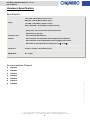
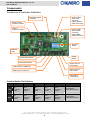
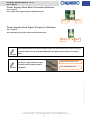
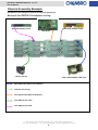
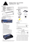
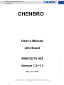
LED Board 80H033216-004 ver. 1.2~1.3
User’s Manual
CHENBRO
User’s Manual
LED Board
Version 1.2~1.3
May / 28 / 2008
15Fl., No.150, Jian Yi Road, Chung Ho City, Taipei Hsien, Taiwan R.O.C.,
Tel: +886 2 82265500 Fax: +886 2 82265392 Email: [email protected]
1
w w w . c h e n b r o . c o m
80H033216-004
LED Board 80H033216-004 ver. 1.2~1.3
User’s Manual
Copyright
Copyright © 2006 CHENBRO Micom Co., Ltd.. All rights reserved.
Unless otherwise indicated, all materials in this manual are copyrighted by CHENBRO Micom Co., Ltd.. All rights
reserved. No part of this manual, either text or image may be used for any purpose other than internal use within
purchasing company. Therefore, reproduction, modification in any form or by any means, electronic, mechanical or
otherwise, for reasons other than internal use, is strictly prohibited without prior written permission.
CHENBRO Micom Co., Ltd. reserves the right to make improvement and modification to the products indicated in
this manual at any time. Specifications are therefore subject to change without prior notice.
Information provided in this manual is intended to be accurate and reliable. However, CHENBRO Micom Co., Ltd.,
assumes no responsibility for its use, nor for any infringements upon the rights of third parties, which may result from
its use.
Technical Support
CHENBRO works hard to offer our customers maximum performance from our chassis. But in case you
have any problem with our product you can find supports from the following resources.
Web Support
Detail information of our products is in our website. You can find technical updates, installation guides, FAQs,
technical specifications and more. Our web address is: www.chenbro.com.
Email Support
You can also fill out the technical support form at our Technical Support page. You technical issue inquiries will be
sent directly to our support professionals.
Phone Support
You can also contact CHENBRO HQ or branch office for immediate support; contact Information is as
CHENBRO HQ
CHENBRO Europe B.V.
CHENBRO Micom (USA) Inc.
Tel: 886-2-8226-5500
Tel: 31-40-295-2045
Tel: 1-909-947-3200
Fax: 886-2-8226-5423
Fax: 31-40-295-2044
Fax : 1-909-947-4300
15Fl., No.150, Jian Yi Road, Chung Ho City, Taipei Hsien, Taiwan R.O.C.,
Tel: +886 2 82265500 Fax: +886 2 82265392 Email: [email protected]
2
w w w . c h e n b r o . c o m
following:
LED Board 80H033216-004 ver. 1.2~1.3
User’s Manual
Contents
Copyright......................................................................................................................................................2
Technical Support......................................................................................................................................2
Contents .......................................................................................................................................................3
Revision History.........................................................................................................................................4
Hardware Specification ............................................................................................................................5
Specification........................................................................................................................................5
Accommodation Chassis.................................................................................................................5
Components ................................................................................................................................................6
Connectors & Switches Definition ................................................................................................6
Power Supply Alarm Mute Connector Definition.......................................................................7
Power Supply Alarm Signal Connector Definition ....................................................................7
Chassis Assembly Example....................................................................................................................8
Example for RM31616 backplane wiring......................................................................................8
w w w . c h e n b r o . c o m
15Fl., No.150, Jian Yi Road, Chung Ho City, Taipei Hsien, Taiwan R.O.C.,
Tel: +886 2 82265500 Fax: +886 2 82265392 Email: [email protected]
3
LED Board 80H033216-004 ver. 1.2~1.3
User’s Manual
Revision History
Date
May / 28 / 2008
Modifications
z First Release
w w w . c h e n b r o . c o m
15Fl., No.150, Jian Yi Road, Chung Ho City, Taipei Hsien, Taiwan R.O.C.,
Tel: +886 2 82265500 Fax: +886 2 82265392 Email: [email protected]
4
LED Board 80H033216-004 ver. 1.2~1.3
User’s Manual
Hardware Specification
Specification
Power LED – Blue ( When Power is On )
Display
HDD LED – Yellow (When HDD is busy )
Error LED – Red (When system is error )
LAN1, LAN2 LED – Green (When network is busy)
z One power, one reset and one alarm mute button
z One buzzer for alerting
Connectors and
z Two standard USB 2.0 ports
Switches
z One connector for Redundant Power Supply failure detection
z One connector to mute Redundant Power Supply built-in alarm
z DIP switch to specify thermal warning level (55℃ or 65℃)
Dimensions
104.2 (L) x 43 (W) x 1.6 (Thickness) mm
PCB Material
FR4 4layer
Accommodation Chassis
RM11600
z
RM11602
z
RM13106
z
RM21600
z
RM21804
z
RM31616
z
RM41500
w w w . c h e n b r o . c o m
z
15Fl., No.150, Jian Yi Road, Chung Ho City, Taipei Hsien, Taiwan R.O.C.,
Tel: +886 2 82265500 Fax: +886 2 82265392 Email: [email protected]
5
LED Board 80H033216-004 ver. 1.2~1.3
User’s Manual
Components
Connectors & Switches Definition
Power supply
alarm mute
connector
(Yellow & Black
Cable from PSU)
Backplane signal
connector
System signal
connector to M/B
USB 2.0
connector to M/B
Power supply
alarm signal
connector
(Red & Black
Cable from PSU)
Function
Switch
USB 2.0
Ports
Power
Switch
System Reset Switch
Alarm Mute Switch
Green LED On:
LAN 2 Busy
Yellow LED on: HDD busy
Green LED On:
LAN 1 Busy
Blue LED on: Power On
Red LED on:
System Error
SW 1
SW 2
SW 3
SW 4
SW 5
SW 6
ON
Fan1
Monitoring
Enable
Fan2
Monitoring
Enable
Fan3
Monitoring
Enable
Fan4
Monitoring
Enable
Fan5
Monitoring
Enable
System Alarm
Temperature is 65°C
OFF
Fan1
Monitoring
Disable
Fan2
Monitoring
Disable
Fan3
Monitoring
Disable
Fan4
Monitoring
Disable
Fan5
Monitoring
Disable
System Alarm
Temperature is 55°C
15Fl., No.150, Jian Yi Road, Chung Ho City, Taipei Hsien, Taiwan R.O.C.,
Tel: +886 2 82265500 Fax: +886 2 82265392 Email: [email protected]
6
w w w . c h e n b r o . c o m
Function Switch Pin Definition
LED Board 80H033216-004 ver. 1.2~1.3
User’s Manual
Power Supply Alarm Mute Connector Definition
Pin 1: Ground
Pin 2: Alarm mute signal output to PSU (Active low)
Pin 1
Pin 2
Power Supply Alarm Signal Connector Definition
Pin 1: Ground
Pin 2: PSU fail signal (TTL) input from PSU (Active low)
Pin 2
Pin 1
Only redundant PSU come with the failure alarm and alarm mute reset control via signal
connector. Make sure the redundant PSU that user applied come with the connectors
above.
This picture shows the standard
Mute (Yellow & Black wire)
“2510 2-pin” type PSU alarm signal
connectors which fitting Chenbro
TTL (Red & Black wire)
LED board.
w w w . c h e n b r o . c o m
15Fl., No.150, Jian Yi Road, Chung Ho City, Taipei Hsien, Taiwan R.O.C.,
Tel: +886 2 82265500 Fax: +886 2 82265392 Email: [email protected]
7
LED Board 80H033216-004 ver. 1.2~1.3
User’s Manual
Chassis Assembly Example
See below for the example of how the wiring to be performed.
Example for RM31616 backplane wiring
Slim ODD adaptor board
Slim FDD adaptor board
LED Board
Chassis Fan x4
SAS / SATA-II RAID / HBA Card
Mini-SAS cable (BP to Host Adaptor)
w w w . c h e n b r o . c o m
Chassis fans wiring
Fan Signal cable (BP to LED board)
Slim ODD power cable
Slim FDD power cable
15Fl., No.150, Jian Yi Road, Chung Ho City, Taipei Hsien, Taiwan R.O.C.,
Tel: +886 2 82265500 Fax: +886 2 82265392 Email: [email protected]
8