1
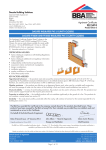
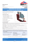
Dacatie Building Solutions APPROVAL INSPECTION TESTING CERTIFICATION Quantum Profile Systems Ltd Salmon Fields Royton Oldham Lancashire OL2 6JG Tel: 0161 627 4222 Fax: 0161 627 4333 TECHNICAL APPROVALS FOR CONSTRUCTION Agrément Certificate 98/3474 e-mail: [email protected] website: www.dacatie.co.uk Product Sheet 1 DACATIE INSULATED PVC-U CAVITY CLOSERS DACATIE SUPAFIX (SF), SUPAFIX FIRE RATED (SFR) AND SUPERFIX MULTICLOSER INSULATED PVC-U CAVITY CLOSERS This Agrément Certificate Product Sheet (1) relates to Dacatie Supafix (SF), Supafix Fire Rated (SFR) and Supafix Multicloser Insulated PVC-U Cavity Closers, for use as cavity closers (cavity width 50 mm to 110 mm) and to form an opening in masonry walls. (1) Hereinafter referred to as ‘Certificate’. CERTIFICATION INCLUDES: • factors relating to compliance with Building Regulations where applicable • factors relating to additional non-regulatory information where applicable • independently verified technical specification • assessment criteria and technical investigations • design considerations • installation guidance • regular surveillance of production • formal three-yearly review. KEY FACTORS ASSESSED Hygrothermal behaviour — the products meet and exceed the minimum thermal resistance path of 0.45 m2·K·W–1 as required by the Accredited Construction Details (version 1.0). Default -values (psi) in BRE Information Paper IP 1/06 may, therefore, be used for jamb and sill junctions in SAP or SBEM (see section 6). Weather resistance — the products are effective as a damp-proof barrier and, when used in a suitable wall construction, will resist the passage of water into the interior of the building in flush and check reveal installations (see section 7). Structural stability — in terms of wind loading resistance, the products can be used in all areas of the UK. The products must not be used to support loads from the masonry (see section 8). Properties in relation to fire — the installed products will not contribute significantly to the growth of a fire. The products do not constitute a cavity barrier, except Dacatie Supafix Fire Rated (SFR) (see section 9). Durability — the cavity closer profiles, protected within the cavity, will continue to function for the normal expected life of a building (see section 11). The BBA has awarded this Certificate to the company named above for the products described herein. These products have been assessed by the BBA as being fit for their intended use provided they are installed, used and maintained as set out in this Certificate. On behalf of the British Board of Agrément Date of Second issue: 27 January 2014 John Albon — Head of Approvals Claire Curtis-Thomas Originally certificated on 20 March 1998 Energy and Ventilation Chief Executive The BBA is a UKAS accredited certification body — Number 113. The schedule of the current scope of accreditation for product certification is available in pdf format via the UKAS link on the BBA website at www.bbacerts.co.uk Readers are advised to check the validity and latest issue number of this Agrément Certificate by either referring to the BBA website or contacting the BBA direct. British Board of Agrément Bucknalls Lane Watford Herts WD25 9BA ©2014 Page 1 of 10 tel: 01923 665300 fax: 01923 665301 e-mail: [email protected] website: www.bbacerts.co.uk Regulations In the opinion of the BBA, the Dacatie Supafix (SF), Supafix Fire Rated (SFR) and Supafix Multicloser Insulated PVC-U Cavity Closers, if installed, used and maintained in accordance with this Certificate, will meet or contribute to meeting the relevant requirements of the following Building Regulations (the presence of a UK map indicates that the subject is related to the Building Regulations in the region or regions of the UK depicted): The Building Regulations 2010 (England and Wales) (as amended) Requirement: B3(4) Internal fire spread (structure) Comment: Dacatie Supafix Fire Rated (SFR) closer can contribute to a construction satisfying this Requirement. See section 9.5 of this Certificate. Requirement: C2(b) Resistance to moisture Comment: The products have adequate resistance to the ingress of rain and wind-driven spray and so can contribute towards the wall satisfying this Requirement. See section 7 of this Certificate. Requirement: C2(c) Resistance to moisture Comment: The products will not constitute a significant condensation risk and so can contribute towards the wall satisfying this Requirement. See sections 6.2 and 6.3 of this Certificate. Requirement: L1(a)(i) Conservation of fuel and power Comment: Regulation: 7 Materials and workmanship Comment: Regulation: 26 CO2 emission rates for new buildings The products can contribute to minimising heat loss at jambs and sills. See section 6.1 of this Certificate. The products are acceptable. See section 11 and the Installation part of this Certificate. See section 6.1 of this Certificate. Comment: The Building (Scotland) Regulations 2004 (as amended) Regulation: 8(1) Regulation: Standard: 9 2.4 3.10 3.15 6.1(b) 6.2 7.1(a)(b) Statement of sustainability The products can contribute to satisying the relevant requirements of Regulation 9, Standards 1 to 6, and, therefore will contribute to a construction meeting a bronze level of sustainability as defined in this Standard. In addition the products can contribute to a construction meeting a higher level of sustainability as defined in this Standard, with reference to clauses 7.1.4(1)(2) [Aspects 1(1)(2) and 2(1)], 7.1.6(1)(2) [Aspects 1(1)(2) and 2(1)] and 7.1.7(1)(2) [Aspect 1(1)(2)]. See section 6.1 of this Certificate. Comment: Regulation: Carbon dioxide emissions Building insulation envelope The products can contribute to minimising heat loss at jambs and sills, with reference to clauses 6.2.3(1), 6.2.4(1)(2) and 6.2.5(2). See section 6.1 of this Certificate. Comment: Standard: Condensation The products will not constitute a significant condensation risk and so can contribute towards the wall satisfying this Standard, with reference to clauses 3.15.1(1)(2), 3.15.4(1)(2) and 3.15.5(1)(2). See sections 6.2 and 6.3 of this Certificate. Comment: Standard: Standard: Precipitation The products have adequate resistance to the ingress of rain and wind-driven spray and so can contribute towards the wall satisfying this Standard, with reference to clauses 3.10.1(1)(2) and 3.10.3(1)(2). See section 7 of this Certificate. Comment: Standard: Building standards applicable to construction Cavities The Dacatie Supafix Fire Rated (SFR) closer can contribute to a construction satisfying this Standard, with reference to clause 2.4.1(1)(2) and Annex 2.B(1) or 2.D(2). See section 9.5 of this Certificate. Comment: Standard: Durability, workmanship and fitness of materials The products can contribute to a construction satisfying this Regulation. See section 11 and the Installation part of this Certificate. Comment: 12 Building standards applicable to conversions All comments given for these products under Regulation 9, Standards 1 to 6, also apply to this Regulation, with reference to clause 0.12.1(1)(2) and Schedule 6(1)(2). Comment: (1) Technical Handbook (Domestic). (2) Technical Handbook (Non-Domestic). The Building Regulations (Northern Ireland) 2012 Regulation: 23 Fitness of materials and workmanship Comment: Regulation: 28(b) Resistance to moisture and weather The products are acceptable. See section 11 and the Installation part of this Certificate. The products have adequate resistance to the ingress of rain and wind-driven spray and so can contribute towards the wall satisfying this Regulation. See section 7 of this Certificate. Comment: Regulation: Comment: 29 Condensation The products will not constitute a significant condensation risk and so can contribute towards the wall satisfying this Regulation. See section 6.3 of this Certificate. Page 2 of 10 Regulation: 35(4) Regulation: Regulation: Internal fire spread — Structure The Dacatie Supafix Fire Rated (SFR) closer can contribute to a construction satisfying this Regulation. See section 9.5 of this Certificate Comment: 39(a)(i) 40(2) Comment: Conservation measures Target carbon dioxide emission rate The products can contribute to minimising heat loss at jambs and sills. See section 6.1 of this Certificate. Construction (Design and Management) Regulations 2007 Construction (Design and Management) Regulations (Northern Ireland) 2007 In the opinion of the BBA, there is no information in this Certificate which relates to the obligations of the client, CDM co-ordinator, designer and contractors under these Regulations. Additional Information NHBC Standards 2014 NHBC accepts the use of Dacatie Supafix (SF), Supafix Fire Rated (SFR) and Supafix Multicloser Insulated PVC-U Cavity Closers, provided they are installed, used and maintained in accordance with this Certificate, in relation to NHBC Standards, Chapter 6.1 External masonry walls. Technical Specification 1 Description 1.1 The Supafix (SF) and Supafix Multicloser closers comprise a PVC-U outer profile enclosing a closed-cell expanded polystyrene core (EPS, declared thermal conductivity D 0.038 W·m–1·K–1) in accordance with BS EN 13163 : 2012, or extruded polystyrene core (XPS, declared thermal conductivity D 0.029 W·m–1·K–1) in accordance with BS EN 13164 : 2012. 1.2 The Supafix SFR (Fire Rated system) comprises a PVC-U outer profile enclosing a polythene encapsulated mineral wool insulation (declared thermal conductivity D 0.037 W·m–1·K–1), in accordance with BS EN 13162 : 2012. 1.3 Dacatie Supafix (SF), Supafix Fire Rated (SFR) and Supafix Multicloser Insulated PVC-U Cavity Closers are available in the sizes to suit the cavity widths shown in Table 1 and Figure 1. Table 1 Sizes and cavity widths Closer type Length (m) Cavity width (mm) Supafix (SF) 2.1 and 3.0 50, 55, 60, 65, 70, 75, 80, 85, 90, 95, 100, 105 and 110 Supafix Fire Rated (SFR) 2.4 50, 80, 90 and 100 Supafix Multicloser 2.4 50, 65, 75, 85 and 100(1) (1) Supplied with insulation prenotched to cut to the required cavity width. Page 3 of 10 Figure 1 Supafix closers (all dimensions in mm) (example sizes) 1.4 The PVC-U profiles include the following features: • flanges that fit over both leaves of masonry • flanges with nibs to aid plaster adhesion. 1.5 The Supafix range of closers are designed primarily for second fix applications when a frame former is not required. They can be simply pushed into position in the cavity and nailed to the surrounding masonry (see Figure 2). Page 4 of 10 Figure 2 Typical jamb details 2 Manufacture 2.1 The cavity closer profiles are manufactured from unplasticised polyvinyl chloride (PVC-U) and are produced by conventional extrusion techniques. Insulation is cut to size and fitted into them manually, where necessary with the aid of an acrylic sealant. 2.2 As part of the assessment and ongoing surveillance of system quality, the BBA has: • agreed with the manufacturer the quality control procedures and system testing to be undertaken • assessed and agreed the quality control operated over batches of incoming materials • monitored the production process and verified that it is in accordance with the documented process • evaluated the process for management of nonconformities • checked that equipment has been properly tested and calibrated • undertaken to carry out the above measures on a regular basis through a surveillance process, to verify that the specifications and quality control operated by the manufacturer are being maintained. 2.3 The management system of Quantum Profile Systems Ltd has been assessed and registered as meeting the requirements of BS EN ISO 9001 : 2008 by SGS (Certificate GB92/1247) and BS EN ISO 14001 : 2004 by SGS (Certificate GB13/8840). 3 Delivery and site handling 3.1 Cavity closer profiles are delivered in packs of one type. Each pack carries an instruction leaflet bearing the marketing company’s name and the BBA identification mark incorporating the number of this Certificate. 3.2 Packs of cavity closer profiles should be stored flat and under cover in a clean area away from direct sunlight and excessive heat and supported along their length to prevent distortion or damage. Profiles should be protected from vehicular and pedestrian traffic. Assessment and Technical Investigations The following is a summary of the assessment and technical investigations carried out on Dacatie Supafix (SF), Supafix Fire Rated (SFR) and Supafix Multicloser Insulated PVC-U Cavity Closers. Design Considerations 4 General 4.1 Dacatie Supafix (SF), Supafix Fire Rated (SFR) and Supafix Multicloser Insulated PVC-U Cavity Closers are for use in masonry walls with cavity widths in the range of 50 mm to 110 mm. The products close the cavity at openings without forming a thermal bridge, provide a damp-proof barrier between inner and outer wall leaves at the point of closure, and can be used to establish the cavity width and to form an opening and avoid the need for cutting bricks and blocks. 4.2 The products are suitable for use with timber, PVC-U, aluminium or steel window and door frames. The closers are non-loadbearing and window and door frames must be fixed independently to the masonry. Proprietary window/door frame fixings, which may be recommended by the manufacturer, are outside the scope of this Certificate. Page 5 of 10 4.3 The products are intended for use in a flush jamb construction. However, with the small flange removed at the factory, the products may also be used in a check reveal application and to fit the window after completion of the masonry, as is conventional practice in some areas. 4.4 By virtue of the nibs down the length of the PVC-U flange, the products can provide a key for traditional plaster finishes (see also section 14.7). 4.5 Masonry walls into which the closers are incorporated must be constructed in accordance with one or more of the following technical specifications: • BS EN 1996-1-1 : 2005, BS EN 1996-1-2 : 2005, BS EN 1996-2 : 2006, BS EN 1996-3 : 2006 and their relevant National Annexes • the national Building Regulations: England and Wales — Approved Document A1/2, Section 1C Scotland — Mandatory Standard 1.1(1)(2), Small Buildings Guide (1) Technical Handbook (Domestic). (2) Technical Handbook (Non-Domestic). Northern Ireland — Technical Booklet D. 4.6 When the systems are used with the head vent section and suitably-sized trickle ventilator, they can contribute to satisfying the background ventilation requirements of the various national Building Regulations. Details of ventilators covered by an Agrément Certificate can be found on the BBA website. 5 Practicability of installation The products are designed to be installed by a competent general builder, or a contractor, experienced with these types of products. 6 Hygrothermal behaviour 6.1 The products can contribute to maintaining continuity of thermal insulation at jambs and sills in wall openings. The path of minimum thermal resistance through the closers, calculated to BRE Information Paper IP 8/08, is at least 0.45 m2·K·W–1, when used in jambs and sills with the window/door frame set back 30 mm or more into the wall cavity (see Figure 2). Example junction details shown in Figure 2 are acceptable and the corresponding heat loss rates -values (psi) in BRE Information Paper IP 1/06, Table 3, may be used in carbon emission calculations in Scotland and Northern Ireland. Attention must be given to the correct set-back in order to ensure compliance with these requirements. Detailed guidance on limiting heat loss and air infiltration can be found in: England and Wales — Approved Documents to Part L and, for new thermal elements to existing buildings, Accredited Construction Details (version 1.0). See also SAP 2009 Appendix K and the iSBEM User Manual for new-build Scotland — Accredited Construction Details (Scotland) Northern Ireland — Accredited Construction Details (version 1.0). 6.2 Jambs and sills incorporating the products in accordance with section 6.1 will adequately limit the risk of local surface condensation. 6.3 Under normal domestic conditions, the level of interstitial condensation associated with the products will be low and the risk of any resultant damage minimal. 6.4 Door frames installed with proprietary fixings which cannot be set back into the wall cavity by a minimum of 30 mm may require additional thermal insulation, for example insulated dry lining, to minimise excessive heat loss and the risk of excessive surface condensation. 6.5 The junctions between the wall and the front and back of the window/door frame must be effectively sealed. 7 Weather resistance 7.1 The products are effective as a vertical damp-proof barrier at jambs of window and door openings in masonry constructions, where a brick/block closer and damp-proof course (dpc) detail would normally be used. The closers are also effective as a horizontal damp-proof barrier at the sill or threshold. 7.2 In installations with a flush (in-line) wall opening and a minimum window set back of 30 mm (see section 6.1), the products are suitable for use in the exposure zones 1 (sheltered), 2 (moderate) and 3 (severe), as depicted in the map in section 3.1 of BRE Report BR 262 : 2002. In this application, the closers may also be considered suitable for use in other areas where a conventional return brick/block closer detail with dpc has been found to provide adequate resistance to the penetration of wind-driven rain. Page 6 of 10 7.3 The products may also be used to construct a check reveal (see Figure 2). In this construction, in which the window is positioned in a rebate behind the outer leaf of the jamb, the products are suitable for use in exposure zones up to and including zone 4 (very severe) as depicted in the map shown in section 3.1 of BRE Report BR 262 : 2002 which covers all exposure zones in the United Kingdom. 8 Structural stability 8.1 The products are non-loadbearing and must not be used to support loads from the masonry. Lintels are required above window or door openings. 8.2 The products will not have an adverse effect on the structural stability of brickwork or blockwork walls constructed in the conventional manner in accordance with normal good practice as defined in the Standards listed in section 4.5 of this Certificate. Use of the products does not obviate the need for conventional wall ties around the openings. 8.3 Window and door frames should be fixed to the masonry by conventional means, in addition to any fixings to the closers (outside the scope of this Certificate). 9 Properties in relation to fire Dacatie Supafix (SF) and Supafix Multicloser 9.1 The installed products will not contribute significantly to the growth of a fire. 9.2 The products do not constitute a cavity barrier against the penetration of smoke and flame in the context of the Building Regulations. 9.3 The use of the products is not prevented in England and Wales, where generally cavity barriers are not required around openings in masonry wall construction. 9.4 In Scotland and Northern Ireland, the products are only suitable for use in conjunction with a cavity barrier meeting the performance requirements defined in: Scotland — Mandatory Standard 2.4, clause 2.4.1(1)(2) and Annex 2.B(1) or 2.D(2) (1) Technical Handbook (Domestic). (2) Technical Handbook (Non-Domestic). Northern Ireland — Technical Booklet E, paragraph 4.38. Dacatie Supafix Fire Rated (SFR) 9.5 On the evidence of the fire test and provided that the closer fits tightly in the cavity, it will act as a cavity barrier at the opening (with respect to the effect of fire penetrating into or out of the cavity), providing 60 minutes fire resistance with respect to integrity and 30 minutes with respect to insulation. Dacatie Supafix (SF), Supafix Fire Rated (SFR) and Supafix Multicloser 9.6 The use of the products does not preclude the need to provide suitable fire protection to steel lintels where this is necessary to satisfy the national Building Regulations. 10 Maintenance To ensure the maximum weathertightness, the silicone seal between window or door frames and masonry must be checked regularly and repairs or renewal carried out promptly. 11 Durability The products are durable when installed in accordance with this Certificate and will not suffer significant degradation when protected within the cavity. The products will continue to function for the normal expected life of a building. 12 Reuse and recyclability The PVC-U profiles of the products can be recycled. Installation 13 General 13.1 Installation of the Dacatie Supafix (SF), Supafix Fire Rated (SFR) and Supafix Multicloser Insulated PVC-U Cavity Closers must be carried out in accordance with the manufacturer’s instructions. 13.2 A cavity barrier may be required (see section 9.2). 13.3 The appropriate closer is selected for the job (see sections 4.1 and 4.3). 13.4 Reference should be made to the typical installation details shown in Figure 2 when reading the installation details given in section 14. The windows shown in this Figure are shown for information only and do not form part of this assessment. Page 7 of 10 13.5 When installing the products, the exposed insulation should always be positioned against the inner leaf (see Figure 2). 13.6 In cutting the products to length, care should be taken to achieve clean, flat, square ends. 13.7 Window/door frames must be set back at least 30 mm behind the inner face of the outer leaf to meet the thermal requirements (see section 6.1). 14 Procedure Closer built in during construction of wall and prior to installation of window or door 14.1 The cavity wall is built to one course above sill/threshold level either side of the opening, ensuring that the course work is level, flat and that all excess mortar is removed. 14.2 A section of closer is cut to length and pushed into the sill cavity. 14.3 The jamb closers are cut to length, to oversail the sill closer by 50 mm. The PVC-U flanges are cut away at the base of the closer, which is subsequently pushed into the cavity, propped in a vertical position and butted against the sill closer with the cut flanges seated on the masonry at sill level. The closer is secured (jamb section only) to the masonry through the flange using galvanized or non-ferrous clout nails (outside the scope of this Certificate) through the overlapping flange(s). 14.4 The procedures for flush and rebated jambs are essentially the same as described in sections 14.1 to 14.3. However, for the rebated jambs application the following should be noted: • there is no flange at the base of the outer PVC-U jamb section to be removed • the sill section should be cut to sill length plus twice the rebated length • where a timber window frame is used, a dpc strip should be positioned between the frame and outer leaf. 14.5 Appropriate insulated lintels and ancillary damp-proof protection are butted onto (but not supported by) the jamb closers at the head, and window/door frames are fixed to the outer leaf with proprietary fixings (outside the scope of this Certificate). 14.6 An effective sealant is applied over a back-up strip between the front and back of the window/door frame and the inner and outer leaf. 14.7 Either wet plaster or a dry lining on plaster dabs is applied to the internal reveal. In locations where the plaster may be subject to repeated impact (eg at door reveals from door slamming) it is recommended that wet plaster should be reinforced by hessian scrim or, preferably, replaced by dry lining. Closer built in after construction of wall and prior to installation of window or door (second fix) 14.8 The closers may be incorporated into the wall after construction and prior to the installation of the window or door frame. 14.9 A section of closer is cut to length and pushed into the sill cavity. 14.10 The jamb closers are cut to length, to oversail the sill closer by 50 mm. The PVC-U flanges are cut away at the base of the closer, which is subsequently pushed into the cavity, propped in a vertical position and butted against the sill closer with the cut flanges seated on the masonry at sill level. The closer is secured (jamb section only) to the masonry through the flange using galvanized or non-ferrous clout nails (outside the scope of this Certificate). Closer built in with window or door frame 14.11 The closers may be incorporated into the wall after pre-fixing to the window or door frame. 14.12 The closer lengths are cut as described in sections 14.2, 14.3 and 14.4 and the closer secured to the window or door frame through the PVC-U flange (or body of the closer), using galvanized or non-ferrous clout nails(1) (timber frame), or self-tapping screws(1) (PVC-U or metal frame). (1) Outside the scope of this Certificate. 14.13 The window or door frame with closers attached is positioned with the sill closer in the cavity. The masonry is built up around the window/door frame and jamb closer assembly and the installation completed as described in sections 14.4 to 14.6. Closer built in with timber template 14.14 A section of closer is cut to length and pushed into the sill cavity. 14.15 The jamb closers are cut as described in section 14.3 and tacked to the top of the sides of a timber template, cut to the size of the opening. 14.16 The template is positioned on the sill with the jamb closers extending into the cavity and the wall built up around the jamb closers as detailed in section 14.4. 14.17 As the wall approaches head height the tacks, and their timber template, are removed. 14.18 The wall is completed around the opening as given in sections 14.5 and 14.6. Page 8 of 10 Refurbishment 14.19 The closers are suitable for use in refurbishment work. For this application the opening must first be ‘cleaned’ ready to take the new closer. 14.20 The closer lengths are cut as described in sections 14.2 to 14.4, inserted into the cavity (jamb sections before sill) and secured (jamb section only) to the masonry through the flange using galvanized or non-ferrous clout nails (outside the scope of this Certificate). 14.21 The window or door frame is then fixed to masonry (fixings outside the scope of this Certificate) and the installation completed as described in sections 14.5 and 14.6. Technical Investigations 15 Tests Tests were carried out on the PVC-U extrusions to determine: • shrinkage on heating • gelation by immersion in acetone. 16 Investigations An assessment was made of: • heat loss and condensation risk in accordance with the Accredited Construction Details (version 1.0) (England and Wales and Northern Ireland) and the Accredited Construction Details (Scotland) • weather resistance of the products when installed in accordance with the manufacturer’s instructions • the practicability of the installation • fire resistance and structural stability of walls incorporating the products • durability of the components used in the construction of the products • the manufacturing process was evaluated, including the methods adopted for quality control, and details were obtained of the quality and compositions of materials used. Bibliography BS EN 1996-1-1 : 2005 Eurocode 6 : Design of masonry structures — General rules for reinforced and unreinforced structures NA to BS EN 1996-1-1 : 2005 UK National Annex to Eurocode 6 : Design of masonry structures — General rules for reinforced and unreinforced structures BS EN 1996-1-2 : 2005 Eurocode 6 : Design of masonry structures — General rules — Structural fire design NA to BS EN 1996-1-2 : 2005 UK National Annex to Eurocode 6 : Design of masonry structures — General rules — Structural fire design BS EN 1996-2 : 2006 Eurocode 6 : Design of masonry structures — Design considerations, selection of materials and execution of masonry NA to BS EN 1996-2 : 2006 UK National Annex to Eurocode 6 : Design of masonry structures — Design considerations, selection of materials and execution of masonry BS EN 1996-3 : 2006 Eurocode 6 : Design of masonry structures — Simplified calculation methods for unreinforced masonry structures NA to BS EN 1996-3 : 2006 UK National Annex to Eurocode 6 : Design of masonry structures — Simplified calculation methods for unreinforced masonry structures BS EN 13162 : 2012 Thermal insulation products for buildings — Factory made mineral wool (MW) products Specification BS EN 13163 : 2012 Thermal insulation products for buildings — Factory made expanded polystyrene (EPS) products — Specification BS EN 13164 : 2012 Thermal insulation products for buildings — Factory made extruded polystyrene foam (XPS) products — Specification BS EN ISO 9001 : 2008 Quality management systems — Requirements BS EN ISO 14001 : 2004 Environmental management systems— Requirements with guidance for use BRE Information Paper IP 1/06 Assessing the effects of thermal bridging at junctions and around openings BRE Information Paper IP 8/08 Determining the minimum thermal resistance of cavity closers BRE Report BR 262 : 2002 Thermal insulation : avoiding risks Page 9 of 10 Conditions of Certification 17 Conditions 17.1 This Certificate: • relates only to the product/system that is named and described on the front page • is issued only to the company, firm, organisation or person named on the front page — no other company, firm, organisation or person may hold or claim that this Certificate has been issued to them • is valid only within the UK • has to be read, considered and used as a whole document — it may be misleading and will be incomplete to be selective; • is copyright of the BBA • is subject to English Law. 17.2 Publications, documents, specifications, legislation, regulations, standards and the like referenced in this Certificate are those that were current and/or deemed relevant by the BBA at the date of issue or reissue of this Certificate. 17.3 This Certificate will remain valid for an unlimited period provided that the product/system and its manufacture and/or fabrication, including all related and relevant parts and processes thereof: • are maintained at or above the levels which have been assessed and found to be satisfactory by the BBA • continue to be checked as and when deemed appropriate by the BBA under arrangements that it will determine • are reviewed by the BBA as and when it considers appropriate. 17.4 The BBA has used due skill, care and diligence in preparing this Certificate, but no warranty is provided. 17.5 In issuing this Certificate, the BBA is not responsible and is excluded from any liability to any company, firm, organisation or person, for any matters arising directly or indirectly from: • the presence or absence of any patent, intellectual property or similar rights subsisting in the product/system or any other product/system • the right of the Certificate holder to manufacture, supply, install, maintain or market the product/system • actual installations of the product/system, including their nature, design, methods, performance, workmanship and maintenance; • any works and constructions in which the product/system is installed, including their nature, design, methods, performance, workmanship and maintenance • any loss or damage, including personal injury, howsoever caused by the product/system, including its manufacture, supply, installation, use, maintenance and removal. • any claims by the manufacturer relating to CE marking. 17.6 Any information relating to the manufacture, supply, installation, use, maintenance and removal of this product/ system which is contained or referred to in this Certificate is the minimum required to be met when the product/system is manufactured, supplied, installed, used, maintained and removed. It does not purport in any way to restate the requirements of the Health and Safety at Work etc. Act 1974, or of any other statutory, common law or other duty which may exist at the date of issue or reissue of this Certificate; nor is conformity with such information to be taken as satisfying the requirements of the 1974 Act or of any statutory, common law or other duty of care. British Board of Agrément Bucknalls Lane Watford Herts WD25 9BA ©2014 Page 10 of 10 tel: 01923 665300 fax: 01923 665301 e-mail: [email protected] website: www.bbacerts.co.uk