1
Sempell High pressure forged globe valves
Installation and maintenance instructions
High pressure forged steel globe valves - pressure seal T, Y and angle pattern - buttwelded or flanged ends
2.All actuated valves must be securely
palleted or crated,with particular attention,
in order to ensure that parts of actuator do
not extend beyond the packing size.
3. The type of packing must be defined in the
Customer’s order and shall be appropriate
to ensure safe transportation to final
destination and eventual conservation
before installation.
1.2 Handling requirements
A - Packed valves
Pallets:Lifting and handling of the packed
valves in pallets will be carried out
by a fork lift truck, by means of the
appropriate fork hitches.
1 Valve storage
Cases:
1.1 Preparation and preservation for
shipment
All valves are properly packed in order
to protect the parts that are subject to
deterioration during transportation and storage
on site. In particular, the following precautions
should be taken:
1. The valves must be packed with the plug in
the closed position.
1a.Buttwelding end valves: weld ends
surface shall be protected with suitable
protective like Deoxaluminite. The ends
shall be closed with plywood or plastic
discs fixed at the edge by strips.
1b.Flanged end valves: the flange sealing
surfaces (raised faces) of the valves shall
be protected with suitable protective
grease. The end faces of the valve must
be protected with plastic or wooden discs
fixed with straps.
B - Unpacked valves
1. The lifting and the handling of these valves
have to be carried out by using appropriate
means and by respecting the carrying limits.
The handling must be carried out on pallets,
protecting the machined surfaces to avoid
any damage.
2. With large dimensions valves, the sling and
the hooking of the load must be carried out
by using the appropriate tools (brackets,
hooks, fasteners, ropes) and load balancing
tools in order to prevent them from
falling or moving during the lifting and the
handling.
www.pentair.com/valves
© 2012 Pentair plc. All rights reserved.
The lifting of packed valves in cases
will be carried out in the lifting points
and at the center of gravity position
which have been marked. The
transportation of all packed material
must be carried out safely and
following the local safety regulations.
VCIOM-02213-EN 15/11
Sempell High pressure forged globe valves
Installation and maintenance instructions
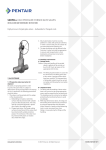
Figure 1
Valve slinging
Globe valves
Y-type globe valves
1.3 Storage and preservation before
installation
In case the valves have to be stored before
installation, the storage has to be carried out
in a controlled way, and has to be performed
in accordance with the following criteria:
1. The valves have to be stocked in a closed,
clean and dry storage room.
2. The plug must be in the closed position,
and the end faces must be protected with
plastic or wooden discs fixed with straps.
If possible, keep the original protection.
3.Periodical checks have to be carried out
in the storage area to verify that the above
mentioned conditions are maintained.
• Do not place consignment packages directly
on the ground.
• Do not expose consignment packages to the
weather or directly to the sun.
• Check the packaging every two months.
Note
Storage in an open area for a limited period can be
considered only in case the valves have appropriate
packing (packed in cases lined with tarred paper,
and contents well protected with barrier sacks).
Caution
For valve handling and/or lifting, the lifting
equipment (fasteners, hooks, etc.) must be sized
and selected while taking into account the valve
weight indicated in the packing list and/or delivery
note. Lifting and handling must be made only by
qualified personnel.
Do not use the lifting points located on the
actuator, if any, to lift the valve. These lifting
points are for the actuator only.
Caution must be taken during the handling to
avoid that this equipment passes over the workers
or over any other place where a possible fall
could cause damage. In any case, the local safety
regulations must be respected.
2 Installation
2.1 Preparation before Installation
1. Carefully remove the valve from the
shipping package (box or pallet) avoiding any
damage to the valve or, in case of automated
valves, to the electric or pneumatic/
hydraulic actuator or instrumentation.
2. The valves are shipped with the ends
protected with caps and a thin layer of
protective grease. Before installing the
valve, remove the caps and clean carefully,
then de-grease both surfaces with a solvent.
Clean the inside of the valve with a clean
cloth.
3. Confirm that the materials of construction
listed on the valve nameplates (service and
temperature) are appropriate for the service
intended and are as specified.
4.Define the preferred mounting orientation
with respect to the system pressure. If
any (see arrow on the body), identify the
upstream side and downstream side.
Warning
See the actuator user manual for the actuator
preparation.
2
Sempell High pressure forged globe valves
Installation and maintenance instructions
2.2 Installation instructions
Globe valves are normally installed in
horizontal pipe with vertical stem.
These valves can also be installed in vertical or
horizontal pipe with stem other than vertical,
but the maintenance is much more difficult.
Globe valves are usually installed on horizontal
pipe with the same flow direction of the arrow
stamped on the body.
For operating temperatures above 200°C
(392°F) a thermal insulation of the valve body
is recommended.
Warning
Before lifting or handling the valve or the valve/
actuator assembly, make sure you have no
limitation to do it. Check if there are some safety
messages attached to the lifting points of the
valve or to the actuator (red rigid label) and, if
any, find the proper document in the user manual
which describes how you can operate under safety
conditions.
Handling and lifting of the valves during
installation MUST be performed following the
same criteria and instruction described in
previous points '1.2 Handling requirements'
and '1.3 Storage and preservation' before
installation.
Warning
Verify that the direction of the flow of the line
corresponds to the arrow indicated on the valve
body. Valves without the arrow are bi-directional.
A - Buttweld valves
1.Open the valve.
2.Position the valve and check for alignment
with the pipe, then proceed with welding,
in accordance with the applicable welding
procedure.
B - Flanged valves
1.Position the valve between the two flanges
of the pipe and put the seal gasket between
valve flange and pipe flange. Ensure that it
is correctly positioned.
2.Assemble the valve to the pipe by means of
bolts which shall be tightened by using the
crossover method.
3.Progressively reach the requested torque.
Important
It is recommended to perform piping flushing
before installation of valve. If this is not possible,
the valves must be set with the plug in full open
position before starting with flushing.
2.3 Valve verification before start up
1. Tighten the packing just enough to prevent
stem leakage. Over-tightening will decrease
packing life and increase the operating
torque. The bolt torque figures for the
packing bolts can be calculated as indicated
in Table 1.
2. Check the operation of the valve by stroking
it to 'full open' and 'full close'.
Important
If piping system is pressurized with water for
testing, and in case the piping system has been
shut down after testing for a long time, the
following recommendations should be adopted.
a. Use corrosion inhibitor with water to
pressurize the piping system.
b. After testing, the piping system should be
depressurized and the test water completely
drained.
3.Should the valve be equipped with electric
actuator, please refer to paragraph 2.5 for
actuator adjustment instruction.
Warning
Before welding, make sure the valve is completely
open.
3
Sempell High pressure forged globe valves
Installation and maintenance instructions
2.4 Periodic valve verification during service
A - Normal checks
1.Verify every half month that there is no
leakage from packing or in the body/bonnet
area. If the leakage has been detected
from the packing, tighten the gland nuts
(Figure 4, pos. 17) slowly and evenly until the
leakage stops, as indicated in Table 1.
If the leakage has been detected from the
body/bonnet, tighten the nuts (Figure 4,
pos. 10) as indicated in Table 2.
If the leakage does not stop, it is necessary
to replace the body/bonnet gasket or to
replace the packing.
2.Every 3-6 months, depending on operating
frequency, verify the greasing of bearings
and the stem thread.
3.For actuated valves, in addition to above,
please refer also to the warnings in the
actuator manual.
B - Preventive actions
1.Every 6 months verify the tightness of gland
bolts.
2.Every 6 months on motorized valves and
every 8 months on hand operated valves,
grease the stem and the bearings.
3.Every 4 years disassemble the critical
service valves and/or actuated valves, verify
the seat surfaces and lap them again when
necessary. Replace the bonnet gasket and
the packing, clean the stem.
4.For the actuator, proceed as indicated in its
maintenance manual.
Table 1 - Bolt torque for packing
bolts
Stem diameter
in
mm
1
25.4
1.25
31.75
1.375 34.92
1.75
44.45
2
50.8
2.25
57.15
2.5
63.5
2.75
69.85
3
76.2
3.25
82.55
3.75
95.25
Bolt diameter
mm
M16
M16
M20
M20
M24
M24
M27
M27
M27
M30
M33
Torque
Nm
14
14
18
18
20
20
23
23
23
28
35
2.5 Adjustment of electric actuators
1.For each valve equipped with actuator,
a torque calculation has been made.
The size of the actuator is selected on the
base of the calculation.
2. The calculated torque is adjusted in the
open and close direction on the actuator.
This torque is calculated to suit the valve.
3.Before assembling an actuator to a valve,
it is necessary to check:
• The technical data of the actuator.
• The correct adjustment torque.
• The operation instruction.
4.Adjustment of the actuator for GLOBE
valves.
Warning
• In the open direction, only the stop has to
be set with the limit switch. In case the limit
switch is not adjusted, the backseat will be
destroyed by the high torque.
• In the close direction, the torque switch
shall be set.
• The adjustment of the limit switches has to
be handled when the actuator is assembled
to the valve according to the operation
instructions.
For this reason note that:
• The calculated torque must be adjusted.
• The closing time must not be too short,
because the energy in the close blocked
position depends on the actuator speed.
• The test performed without pressure under
the piston must be avoided, because the
actuator runs with full speed into the seat
without any reaction.
Table 2 - Bolt torque for bonnet
bolts
Diameter
in
mm
⅜
10
½
12
⅝
16
¾
20
1
24
1⅛
28
1¼
32
Bolt diameter
mm
M10
M12
M16
M20
M24
M28
M32
Torque
Nm
30
70
140
260
580
760
1350
4
Sempell High pressure forged globe valves
Installation and maintenance instructions
Troubleshooting guide
Symptom
Possible cause
Stem packing leaking 1.Gland flange nuts too loose
2.Packing damaged
Body-bonnet leaking 1.Gasket bolting loose (Figure 4, pos. 10)
2.Gasket damage
Valve leaking
1.Valve not fully closed
2.Debris trapped in valve
Jerky operation
3.Sealing surface damaged
1.Packing is too tight
Back seat leaking
1.Back seat damage
Solution
1. Check the gland flange nuts torque
2.Replace packing
1. Tighten bolting (Figure 4, pos. 10)
2.Replace the gasket
1. Close the valve
2. Cycle and flush (with valve open) to
remove debris
3.Recondition the seat surface
1.Loosen gland nuts, cycle the valve,
retighten
1.Recondition the back seat surface
3 Operation and maintenance
instructions
3.1 Operation and maintenance instructions
Please refer to Figure 4
High pressure forged Sempell valves do
not require special care to work properly.
The following instruction will help provide a
satisfactory and long life service.
Assembly
1.All the parts must be cleaned. It is
necessary a visual examination to ensure
that there are no foreign parts inside.
2. The internal seat surface (1.3) must be
carefully lapped in order to avoid any defect.
3. The surfaces of the plug seat (28.1) must be
lapped in order to avoid any defect.
4.Assemble the plug (28) with the plug nut (30)
and screw to the stem (20). Insert now this
unit into the body.
5.Insert the bonnet (2) into the body. Take
care that the operator wears gloves in order
to ensure a careful assembly of the pure
graphite gasket (7), covered with stainless
steel inlets.
6. The ring (6) and the four pieces of the
segment ring (5) must be assembled over
the gasket (7). The segment ring has to be
put into the body groove.
Cautions
• Ensure to perform periodic valve verification
as described in paragraph 2.4.
• In case of actuated valves, always follow the
specific instruction given by the actuator’s
manufacturer.
• Never change the setting of torque and/or
limit switches which have been carefully set
during the final test at our workshop.
Important
• To ensure tightness of pressure seal gasket,
pull up bolts must be tightened when the valve
is under fully hydrostatic pressure test or
twenty-four hours in operation.
• Yearly checking of bolt torque is recommended.
5
Sempell High pressure forged globe valves
Installation and maintenance instructions
Important
The segment ring has to be fixed by the safety
ring. Ensure that the segment ring is in the
correct position.
7. The bonnet must be brought into position
with the necessary bolts and nuts. For the
necessary torque, see Table 2.
8.Install the ground ring (13), the packing of
pure graphite and two rings to the stuffing
room (see Figure 2). The operator MUST
wear gloves.
9. The packing shall be compressed by the
gland (15) and the gland flange (16) with the
cut ring (19) inside. Screw the nuts to the
bolts with the torque indicated in Table 1.
10.Install the indicator (25) on the stem.
11.Assemble the yokenut (21), the two bearings
(22) and the two O-rings (32) to the yoke
with the lubrication nipple, then the gear/
actuator connection flange with the bolts.
12.Assemble the handwheel, the gear or the
actuator to the valve.
Disassembly
1.For a correct disassembly it is necessary to
follow in reverse the assembly instructions.
2.Follow this special remark to disassemble
the seat ring: in the upper part of the body,
in the area of the segment ring, there are
some holes to drive out two parts of the
segment ring by using a pin and a hammer.
Figure 2
Cautions
First, drive out the two parts of the segment
ring as indicated in Figure 3, then the
remaining two parts.
Recommended spare parts
Please refer to Figure 4
• Gasket (7)
• Yoke nut (21)
• Ground ring (13)
• Bearings (22)
• Packing (14)
• Stem (20)
• Globe plug (28) with the plug nut (30)
1. Wired pure graphite.
2. 3 to 4 pure graphite rings with a density
of 1.8 g/cm3.
3. Wired pure graphite.
4.Ground ring.
Figure 3
Segment
ring
Segment
ring
6
Sempell High pressure forged globe valves
Installation and maintenance instructions
Figure VA250.6022 to VA250.6025
Figure 4
Globe valves
Figure
VA250.6022
VA250.6023
VA250.6024
VA250.6025
Class
900
1500
2500
4500
PN
09 (160)
15 (250)
25 (500)
45 (720)
Trim material to API 600
Accessory 18
Item
1
5
Body seat
surface 1.3
13% Cr
Stellite
Plug seating
surface 28.1
13% Cr
Stellite
8
12
Stellite
F316/Stellite
13% Cr
F316/Stellite
Stem 20
13% Cr
13% Cr
17% Cr*
13% Cr
F316 or 17.4
PH below
450°C
* Over 450°C
Screw down check
Material specifications
Item
1
1.1
2
3
4
5
6
7
8
9
10
11
13
14
15
16
17
18
19
21
Body
Body
Bonnet
Yoke
Safety ring
Segment ring
Ring
Gasket
Bolts
Nuts
Plate
Screw
Ground ring
Packing
Gland
Gland flange
Gland nuts
Bolts
Cut ring
Yoke nut
22
25
28
30
32
33
Bearings
Indicator
Plug
Plug nut
O-ring
Handwheel
21
-20°C - 425°C
A105
C22.8
1.0460
A105
C22.8
A105
C22.8
A105
C22.8
A105
A105
A105
C22.8
A105
C22.8
Pure graphite
A193 B7
A194 2H
A194 2H
A193 B7
17Cr 1.4122
Pure graphite
F6
A105
A194 2H
A193 B7
Pure graphite
Bronze B 148 gr.B
or Ni-resist D2
Steel
A105
F6
F6
FKM
Steel
22
-46°C - 425°C
LF2 TT5
1.0411
LF2 TT5
LF2 TT5
LF2 TT5
A105
A105
LF2 TT5
LF2 TT5
Pure graphite
A193 B7
A194 2H
A194 2H
A193 B7
17Cr 1.4122
Pure graphite
F6
A105
A194 2H
A193 B7
Pure graphite
Bronze B 148 gr.B
or Ni-resist D2
Steel
A105
F6
F6
FKM
Steel
23
200°C - 540°C
F1 15Mo3
1.5415
F1 15Mo3
F1 15Mo3
F1 15Mo3
A105
A105
F1 15Mo3
F1 15Mo3
Pure graphite
A193 B7
A194 2H
A194 2H
A193 B7
17Cr 1.4122
Pure graphite
F6
A105
A194 2H
A193 B7
Pure graphite
Bronze B 148 gr.B
or Ni-resist D2
Steel
A105
F6
F6
FKM
Steel
24
250°C - 550°C
F12 13CrMo44
1.7335
F12 13CrMo44
F12 13CrMo44
F12 13CrMo44
A105
A105
F12 13CrMo44
F12 13CrMo44
Pure graphite
A193 B7
A194 2H
A194 2H
A193 B7
17Cr 1.4122
Pure graphite
F6
A105
A194 2H
A193 B8
Pure graphite
Bronze B 148 gr.B
or Ni-resist D2
Steel
A105
F6
F6
FKM
Steel
25
400°C - 575°C
F22 10CrMo910
1.7380
F22 10CrMo910
F22 10CrMo910
F22 10CrMo910
A105
A105
F22 10CrMo910
F22 10CrMo910
Pure graphite
A193 B7
A194 2H
A194 2H
A193 B7
17Cr 1.4122
Pure graphite
F6
A105
A194 2H
A193 B8
Pure graphite
Bronze B 148 gr.B
or Ni-resist D2
Steel
A105
F6
F6
FKM
Steel
26
28
500°C - 650°C
130°C - 650°C
F91 P91
F316 X6CrNiNb1810
1.4903
1.4550
F91
F316 X6CrNiNb1810
F91
F316 X6CrNiNb1810
F91
F316 X6CrNiNb1810
A105
A105
A105
A105
F91
F316 X6CrNiNb1810
F91
F316 X6CrNiNb1810
Pure graphite
Pure graphite
A193 B7
A193 B7
A194 2H
A194 2H
A194 2H
A194 2H
A193 B7
A193 B7
17Cr 1.4122
17Cr 1.4122
Pure graphite
Pure graphite
F6
F6
A105
A105
A194 2H
A194.8
A193 B8
A193 B8
Pure graphite
Pure graphite
Bronze B 148 gr.B Bronze B 148 gr.B
or Ni-resist D2
or Ni-resist D2
Steel
Steel
A105
F316
F6
F6
F6
F6
FKM
FKM
Steel
Steel
7
Sempell High pressure forged globe valves
Installation and maintenance instructions
4 Valve removal
To remove a valve from the line, it is necessary to operate as follows:
1.Obtain permission to work.
Warning
Depressurize the line before starting any operation with the valve in open position. Then close the valve.
2.During the valve cutting operation proceed with care in order to prevent any damage to the
seats.
3.After the removal, clean carefully the valve and close the ends with plastic or wooden discs.
5 Lubricants and special tools
5.1 Lubricants
It is recommended to lubricate the yoke nut, if any, through the yoke nut lubricator every 2 months
by using the following products:
• The bearings are lubricated with usual lubrications for bearings.
• Smear the stem threads with Molykote.
• All other bolts and nuts are assembled with usual lubricator or Molykote.
5.2 Special tools
No special tool is required for the maintenance operations described in this manual.
Table 3 - Grease and lubricant list
Manufacturer
AGIP
API
BP
ESSO
FINA
MOBIL
Q8
SHELL
TEXACO
TOTAL
VISCOL
STATOIL
Grease
GRMUEP2
PGX2
GREASE LTX2
BEACON 2
FINAGREASE HP FINAGREASE EPL2
MOBILUX EP2
REMBRANDT EP2
ALVANIA R2 SUPERGREASE A
MULTIFAK EP2 GREASE L2
MULTIS EP2 MULTIS 2
SIGNAL ROLSFER 2
UHIWAYLI LI G2
6 Operational safety instructions (O.S.I.) in accordance with PED requirements
According to PED-ESR, par. 3.3 and related, the service pressure and temperature are indicated
on the nameplate fixed on the valve.
The Operation Safety Instructions (internal document TD-PED-0020) are indicated in the attached
document (when applicable).
PENTAIR VALVES & CONTROLS
www.pentair.com/valves
All Pentair trademarks and logos are owned by Pentair plc. All other brand or product names are trademarks or registered marks of their respective owners.
Because we are continuously improving our products and services, Pentair reserves the right to change product designs and specifications without notice.
Pentair is an equal opportunity employer. © 2015 Pentair plc. All rights reserved.
8