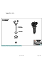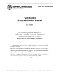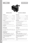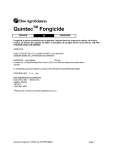
1
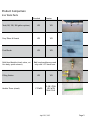
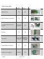
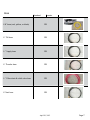
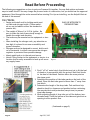
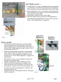
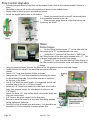
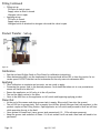
For More Information Contact:
Chemical Containers, INC
Dow Agro Sciences
Dow Agro Sciences
413 ABC Road
Lake Wales, FL 33859
Florida
Jerry Nance
Central and Northern Alabama, Arkansas, Mississippi,
Louisiana, Missouri
Phone: 800-346-7867
Fax: 863-638-1407
[email protected]
www.chemicalcontainers.com
Chemical Containers, Inc
Mike Dubose
11318 Rustic Wheel CT,
Jacksonville, FL 32257
Office: 800-346-7867
Cell: 863-528-4612
Nextel: 162*24053*3
[email protected]
www.chemicalcontainers.com
One Lake Line Drive S.E.
Winter Haven. FL 33884
Office: 863-293-4224
Cell: 863-203-2178
Nextel: 162*36*22795
[email protected]
www.dowagro.com
Jerome Otto
1102 Lakespur Ct.
Scottsbluff, NE 69391
Cell: 308-641-7416
[email protected]
www.telone.com
Dow Agro Services
Dow Agro Services
West Georgia, Southeast Alabama
Chip Giles
6492 Broad Tree Court
Tallahassee, FL 323127
Cell: 229-392-4653
[email protected]
www.dowagro.com
North and South Carolina, East
Georgia
Billy Daniels
1052 DR Hardy Cir.
Dillon, SC 29536
Office: 843-774-3434
Cell: 843-230-7077
Nextel: 132*36*22795
[email protected]
www.dowagro.com
Contents
5
5
6
7
8
9
9
10
10
8
Product Comparison
Iron Work Parts
Flow Control Parts
Hose
Read Before Proceeding
Iron Works
Iron Works (cont.)
Flow Control
Flow Control Upgrades
Hoses
10
11
Product Hoses
Nitrogen Hoses
13
13
Finishing Set Up
Checking for Leaks
Operating Instructions
12
12
12
13
13
14
14
14
14
14
16
15
Premier:
Installing hoses without site glass stand
Installing hoses with glass stand
Filling
Filling Continued
Product Transfer – Set up
Calibration
Applying
Clean Out
Troubleshooting
Additional Instructions
16
Maintenance Guide
16
Nitrogen System with Filling Station
16
Nitrogen System WITHOUT a Filling Station
17
Flush Out Kit Instructions
17
Nitrogen System with Filling Station
17
Nitrogen System WITHOUT a Filling Station
17
Grower Tank
18
18
18
18
19
19
20
21
22
23
24
25
26
27
28
29
30
31
32
33
34
35
36
37
38
39
Helpful Hints
Module Tower
Trash Guards
Nitrogen Rack
Assembly Diagrams & Replacement Parts
Banjo 80 Mesh Filter
Banjo 120 Mesh Filter
6 Row Manifold Assembly
24” Drop Tube
Transfer Hose
Vent Hose
Check Valve Assembly
Digital Flow Meter
Filling Station
Single Filter Assembly
Double Filter Assembly
4 Row Manifold Assembly
On/Off Valve - Standard Kit
Nitrogen Regulator
Transfer Regulator
Site Glass and Stand
Site Glass Assembly
120 Gallon Tank
250 Gallon Tank
On/Off Throttling Valves - Premier Kit
Single Filter Only
Product Comparison
Iron Work Parts
Standard
Premier
Tank(120, 250, 500 gallon options)
YES
YES
Drop Tubes & Guards
YES
YES
Foot Blocks
YES
YES
Bulk Head Module (check valve, orifice body, quick connect)
Filling Station
Module Tower (stand)
Bulk head modules are used
only with 1/8” black hose
YES
YES
1 TOWER
2 OR 3 TOWERS WITH
STACK FOLD April 20, 2012
Page 5
Flow Control Parts
Standard
Premier
Manifold module
YES
YES
Digital Flow Meter (with turbine)
NO
YES
On / Off and throttle valve with
controller
ON / OFF
VALVE ONLY
YES
YES
YES
SINGLE FILTER
100 MESH
DOUBLE FILTERS 80 AND
120 MESH
YES
YES
OPTIONAL
YES
Site Glass
Filter module
Nitrogen Application Regulator
Nitrogen Transfer Regulator
Page 6
April 20, 2012
Hose
Standard
Premier
1/8” hose (red, yellow, or black)
YES
¾” Fill hose
YES
½ ” Supply hose
YES
¾” Transfer hose
YES
½ ” Filter drain & relief valve hose
YES
¾”Vent hose
YES
April 20, 2012
Page 7
Read Before Proceeding
The following are suggestions on how to put your Pressure Kit together. You may find quicker and easier
ways to install this kit. You may change the process/order of construction, but you should use the approved
equipment. Read through the entire manual before starting! For tips on installing, see the Helpful Hints at
the end of this manual.
Iron Works
• Design and install rack for holding metal product tank and nitrogen bottle (These materials are not included in either the standard or
premier kit).
• The weight of Telone II is 10.2 lb./gallon. Be
sure to make the tank frame sturdy enough to
handle the weight and vibration.
• The tanks may be mounted on the equipment or tractor.
• When installing the nitrogen rack, pay attention on
how high it is placed to en-sure accessibility and
ground clearance.
• Nitrogen rack can be designed to mount bottle vertical or horizontal. In either case ensure the nitrogen
regulator is protected from possible damage.
• Mount metal tank on to the rack and secure.
• Attach Filling Station to the implement or tractor in a
location that is easily accessible to hook up all necessary supply hoses.
ONLY USE NITROGEN TO
PRESSURIZE TANK
Figure 1.
1. Find 1”x2”x6” metal stock (foot blocks) and cut to fit the heel
of shank so it runs parallel with the ground. Weld foot blocks
to the heel of the shank. Position above the ware point on
the ripper point.
2. Determine the position of the tube guards on the back of the
shank. Place the first tube guard no more than 1” away from
foot block.
3. Determine the length of the drop tube. Tack weld and trip
shank to check for clearance and position before continuing.
You may decide to add protection (see picture) to prevent
drop tube damage.
4. When adjusting length of drop tube cut off the bottom (nonthreaded end). Pinch the bottom of the tube and grind out an
opening to allow product flow.
( Continued on page 9)
Figure 2.
Page 8
April 20, 2012
Iron Works (cont.)
5. If using black 1/8” hoses - Weld bulk head mounting bracket onto frame to hold Orifice body/Check valve assembly.
Then put quick connects on both sides of the orifice body.
6. When using yellow or red 1/8” hose an orifice body/check
valve assembly is not required. Hose will connect directly
to the top of the drop tubes.
7. Attach quick connects to top of drop tubes.
8. Weld the module tower off center on the implement so
that site glass and manifold are in view of the tractor operator. (See “Helpful Hints” on page 18)
Figure 3.
Flow Control
• Find the filter module and slide it onto the module
tower and secure close to the bottom of the tower.
Leave enough space to attach the filter drain hoses. (If
the dual filter module upgrade is used, place it in the
same position as above).
• Following the placement of the filter on the module
tower, slide on the on/off valve. Secure this on/off
valve in place. (If the single filter module is not being used, go to “Flow Control Upgrades” on page 10 for
instructions)
• Next slide on the 4 or 6 port manifold and secure at
the top of the module tower
• Multiple manifolds will require additional stands
• Locate on/off switch and attach to module on/off
valve and run the cord and switch to the tractor cab
• Leave plenty of loose cord to allow securing the cord
the tractor and allow the implement to operate with
out pulling on the cord
• Position switch box to the desired location. Then open
switch box and cut
April 20, 2012
Figure 4.
Page 9
Flow Control Upgrades
• Following the placement of the filter on the module tower, slide on the turbine module. Secure in
place.
• Next slide on the on/off and throttle module and secure to the module tower.
• Finally, slide on the 4 or 6 port manifold and secure.
• Attach the digital meter cable to the turbine.
•
Attach the control switch to the KZ valves and place
in an accessible location in the cab
•
Place the site gauge stand at a spot that can be easily seen by the driver.
Hoses
Product Hoses
•
On the Filling Station write a “P” on the side with the
two valves and a “N” on the side with one valve.
•
Locate the ¾” hose and run from the ¾” barb from
the Filling Station to the tank outlet marked with a “P”. Cut
to proper length and secure with hose clamps.
•
Connect 1/2” hose from hose barb on Filling Station to
the filter located on the module tower and secure with hose
Figure 5.
clamps.
• Using the same size hose, connect the filter to the site glass and secure with hose clamps.
• Connect the on/off valve to the manifold and secure with hose
clamps.
• Secure 1/2 ” hose from bottom of filter to frame
• String out the 1/8” hose from manifold by following the frame
to the farthest drop tube. Cut this hose and use as a pattern
for the rest of the hoses.
• Cut all 1/8” hoses the same length. It is suggested that all red
or yellow hose to be cut to 15 feet in length.
• Attach all 1/8” hoses from manifold to the check valve/orifice
body. (See upgrade section for attachment of yellow or red
1/8” hoses)
• Attach the black 1/8” hose to the check valve/orifice body and
then run a short black
• 1/8” hose to the quick connect on the drop tube.
• Be sure to place the hoses in an area safe from being pinched
during implement operation.
• Carefully coil up all excess hose and secure. Coils should be approximately 1 foot in diameter to ensure proper flow.
Figure 6.
Page 10
April 20, 2012
Nitrogen Hoses
• Install nitrogen tank in nitrogen rack
• Attach regulator to nitrogen tank
• Run nitrogen hose to nitrogen valve at
the Filling Station
Figure 7.
April 20, 2012
Page 11
Premier:
Installing hoses without site glass stand
• From the filter attach the 1/2” supply hose to the turbine.
• Connect the turbine to the throttle valve (red indicator).
• Connect the throttle valve to the on/off valve (yellow
indicator).
• Connect the on/off valve to the manifold.
Figure 8.
Installing hoses with glass stand
• From the filter attach the 1/2” supply hose to the
turbine.
• Connect the turbine to the site gauge & stand.
• Due to the long length of hose required to connect to
the site stand, DO NOT attach the hose to a plastic
fitting. Always attach it to metal fittings for
• Connect the site gauge to the (KZ valves) throttle
(red) and then to the on/off valve (yellow).
• Connect the on/off valve to the manifold.
Figure 9.
Page 12
April 20, 2012
Finishing Set Up
• Locate orifice body (if using), separate orifice body,
place desired orifice within housing with numbered
side up, close and tighten.
• If orifice bodies are not being used, connect the red
or yellow hose directly to the quick connect on top of
the drop tube
Checking for Leaks
• Pressurize the tank with desired amount of nitrogen.
• Check for leaks at the fittings with soapy water. If
bubbles appear, tighten fitting to seal. If it will not
seal, depressurize the tank and reseal the fitting.
• Once the system is tested, open all valves and ensure
flow of nitrogen to the drop tubes.
Figure 10.
ONLY USE NITROGEN TO
PRESSURIZE TANK
Operating Instructions
Filling
• Let off all pressure in the tank that was just leak tested by connecting the vent hose to the nitrogen coupler at the Filling Station and open the vent valve.
• Connect the transfer hose from the pig to the product valve at the Filling Station.
• Open the fill line to the grower tank and close the product line to the filter
• Make sure the product valve on top of the grower tank, is open.
• Pressurize the pig with nitrogen
• Open the product valve on the pig.
• Transfer the contents of the pig into the grower tank.
• Do not over fill
• Once the product has been transferred to the grower tank, close the pig product valve.
• Disconnect the transfer hose
• Close the nitrogen line at the Filling Station and disconnect
the vent hose
• Reattach the nitrogen bottle to the nitrogen valve at the filling
station.
• Open the nitrogen bottle and set the regulator to the desired
pressure
• Open the nitrogen line at the Filling Station to pressurize the
grower tank
• Open the supply line to the filter. Be sure the applicator on/off
valve on the tower is in the off position.
( Continued on Next Page )
Figure 11.
April 20, 2012
Page 13
Filling Continued
• Filling set up:
Fill valve to tank is open.
Supply valve to filter is closed
Nitrogen valve is open
• Applying set up:
Fill valve is closed.
Supply valve is open
Nitrogen bottle is attached to nitrogen valve and the valve is open
Product Transfer – Set up
Figure 12.
Calibration
• See the enclosed Orifice Guide or Flow Sheet for calibration instructions
• When determining MPH, put the implement in the ground and utilize GPS or time the tractor for accurate speed. DO NOT use the tractor tachometer as the only source to determine MPH.
Applying
• Once calibration is complete and accurate, we are ready to apply.
• Pressurize the grower tank to the desired pressure. Care should be taken not to over pressurize as
excess will have to be bled off.
• Ensure the applicator on/off valve is in the off position
• Turn on the supply valves to the filter
• Once in the field turn on the applicator on/off switch and beginning applying product
Clean Out
• At the end of the season and when grower tank is empty. Blow out all lines into the ground.
• Turn off fill line to grower tank. Turn on supply line to filter. Attach Nitrogen line from regulator to the
product coupler at the Filling Station. Open applicator on/off switch and proceed to blow out all lines
while operating the rig in the field
• Once system is cleaned out, leave grower tank pressurized ( 10 – 15 lbs nitrogen pressure).
• Keep the grower tank sealed at all times. If it is not sealed it will rust and a new tank will need to be
purchased.
Page 14
April 20, 2012
ONLY USE NITROGEN TO
PRESSURIZE TANK
Troubleshooting
• Product not flowing to site glass
Check to make sure the On/Off switch is operating
Check to make sure the valves are open at the grower tank
Check to make sure there is product in the grower tank
Check to make sure the grower tank is pressurized. If the tank is not pressurizing, in
spect the check valve on the nitrogen line.
Clean out the filter
• Product will not flow from pig to grower tank
Check to make sure the Filling Station vent line is connected and the valve is open
Check to make sure the pig is pressurized
Check to make sure the proper valves are open
• Product will not flow evenly to each shank
Ensure all lines are the same length
Check to make sure the coiled 1/8” hose is not coiled any tighter than in 1 foot diam
eter coils.
If check valve/orifice body is used be sure to run a minimum of 10 PSI at the check valve/orifice body assembly.
Check the condition of the diaphragm check valve. Check for bubbles/blistering and dust/dirt. Replace if necessary.
If screens are used, they must all be clean
Ensure all drop tubes are free and clear of debris
• Digital meter is not showing a consistent flow
Check to make sure the throttle & on/off valve is located after the turbine.
Be sure there are no sharp turns in the supply line on either side of the turbine.
Adjust nitrogen pressure to improve sensitivity of product flow.
April 20, 2012
Page 15
Additional Instructions
•
•
•
•
•
•
Follow proper calibration methods
Use the proper Personal Protective Equipment
Keep nitrogen pressure on the grower tank at all times
Each year , inspect all components prior to application and replace questionable parts.
Calibrate each year and double check acres treated to the amount of product applied.
Do not place any product lines or gauges containing product in the tractor cab
Maintenance Guide
Once application of Telone is complete, purge all Telone lines with nitrogen by following these steps1
Nitrogen System with Filling Station
•
•
•
•
•
•
•
•
•
•
Attach nitrogen line to the product side of the filling station
Shut off product ball valve at the top of the tank
Open both valves at the product side of the filling station
Open the on-off valve and regulating valve2 to the system
Open nitrogen supply to flush out remaining Telone in the line
Continue flushing until no Telone is seen coming from the outlet
Open valve on the bottom of the filter body to remove any remaining Telone in the filter body
Turn off the nitrogen valve
Remove filter element from filter body or bodies
Rinse element with diesel fuel and replace back into the filter body
To improve the longevity of your pressure system it is suggested that you also flush the system with
diesel fuel using the same steps from above
Check with your Certified Dealer or Chemical Container Inc on the availability of a diesel Flush Out Kit.
Instructions on the use of the Diesel Flush Out Kit are included in the guide
Once purging is complete disconnect all hoses and close ball valves.
Seal all open hoses by using duct tape to prevent intrusion by insects
Nitrogen System WITHOUT a Filling Station
• Remove the dry lock disconnect from the product side at the top of the tank
• Using a double male dry lock connector, insert into the female dry lock connector at the end of the
hose going to the filter.
• Connect the female dry lock disconnect from the nitrogen bottle to the other side of the double male
dry lock connector.
• Open the on-off valve and regulating valve to the system2
• Open nitrogen supply to flush out remaining Telone in the line
Continue flushing until no Telone is seen coming from the outlets
Open valve on the bottom of the filter body to remove any remaining Telone in the filter body
• Turn off the nitrogen valve
• Remove filter element from filter body or bodies
• Rinse element with diesel fuel and replace back into the filter body
• To improve the longevity of your pressure system it is suggested that you also flush the system with
diesel fuel using the same steps from above
Check with your Certified Dealer or Chemical Container Inc on the availability of a diesel Flush Out
Kit.
Instructions on the use of the Diesel Flush Out Kit are included in the guide
• Once purging is complete disconnect all hoses and close ball valves.
• Seal all open hoses by using duct tape to prevent intrusion by insects
1
2
If using orifice plates, remove before flushing/purging system
This only applies to the Premier System Equipment Maintenance
Page 16
April 20, 2012
Flush Out Kit Instructions3
• If using orifice plates, remove before flushing/purging system
• Fill Flush Out Kit with diesel
• Connect positive and negative electrical terminals of the Flush Out Kit to a battery
Nitrogen System with Filling Station
•
•
•
•
•
•
•
•
Attach Flush Out Kit line to the product side of the filling station
Shut off product ball valve at the top of the tank
Open both valves at the product side of the filling station
Open the on-off valve and regulating valve4 to the system (connect to an electrical source to
operate)4
Turn on switch to the Flush Out Kit to begin purging process
Continue flushing for two minutes after diesel is seen coming from the outlets
Turn off the Flush Out Kit switch
Once purging is complete disconnect all hoses and close ball valves.
Seal all open hoses by using duct tape to prevent intrusion by insects.
Nitrogen System WITHOUT a Filling Station
• Remove the dry lock disconnect from the product side at the top of the tank
• Using a double male dry lock connector, insert into the female dry lock connector at the end of the
hose going to the filter.
• Connect the female dry lock disconnect from the Flush Out Kit to the other side of the double male
dry lock connector.
• Open the on-off valve and regulating valve to the system5
• Switch on Flush Out Kit to start flow of diesel
Continue flushing until no Telone is seen coming from the outlets
Open valve on the bottom of the filter body to remove any remaining Telone in the filter body
• Turn off the Flush Out Kit switch
• Once purging is complete disconnect all hoses and close ball valves.
• Seal all open hoses by using duct tape to prevent intrusion by insects
Grower Tank
•
•
•
•
•
•
3
4
5
Do Not leave the tank open to the atmosphere
Always maintain nitrogen pressure on the tank
Always use nitrogen as the gas in the tank
Always filter product going in and out of the tank
Never put any other liquid in the tank other than Telone* products
Do not weld or cut the tank
If using orifice plates, remove before flushing/purging system
This only applies to the Premier System
This only applies to the Premier System
April 20, 2012
Page 17
Helpful Hints
Module Tower
When attaching the module tower, you may want to put
on a receiver post first for durability and removal for stor-
age.
Figure 13.
Figure 14.
Trash Guards
Trash guards may be attached to prevent the soil and trash from rapping
around product hose and causing damage.
Figure 15.
Nitrogen Rack
•
When designing the nitrogen rack, make a receiver spot for
placing the nitrogen tank.
•
This will help maintain control of the nitrogen bottle as you
lift it into place
Figure 16.
Page 18
April 20, 2012
Assembly Diagrams & Replacement Parts
Banjo 80 Mesh Filter
NOTES: PART BLS15080V FOR
CCIEZFILTERMODA
BLSQ200-R
BLS280
BLS150-GVN
TITLE
CHEMICAL CONTAINERS, INC.
LAKE WALES, FLORIDA, 33859
TEL: 863-638-1407
FAX: 863-638-1863
1 1/2" POLY STRN BOM,VITON GASKET
SIZE DWG NO
B
BLS15080V
REV
00
COMPONENT DRAWING
SCALE: N.A. LAYOUT SHEET
SHEET 1 OF 1
M:\ENGINEERING\COMPONENTS\CCI\TELONE\TELONE PRESSURE KIT\BLS15080V.dft
April 20, 2012
Page 19
Banjo 120 Mesh Filter
NOTES: PART : BLS150120V FOR
CCIEZFILTERMODA
BLSQ200-R
BLS2120
BLS150-GVN
TITLE
CHEMICAL CONTAINERS, INC.
LAKE WALES, FLORIDA, 33859
TEL: 863-638-1407
FAX: 863-638-1863
1 1/2" POLY STRN BOM, VITON GASKET
SIZE DWG NO
B
BLS150120V
REV
00
COMPONENT DRAWING
SCALE: N.A. LAYOUT SHEET
M:\ENGINEERING\COMPONENTS\CCI\TELONE\TELONE PRESSURE KIT\BLS150120V.dft
Page 20
April 20, 2012
SHEET 1 OF 1
6 Row Manifold Assembly
NOTES:
M200
TE1/4BH
CCIEZMANMODBKTA
TEME6PORT
FB394
FBMQ68V-44
FB406A
FB459B
TITLE
CHEMICAL CONTAINERS, INC.
LAKE WALES, FLORIDA, 33859
TEL: 863-638-1407
FAX: 863-638-1863
MANIFOLD MODULE 6 PORTS
HZ953
SIZE DWG NO
B
CCIEZMANMOD - 6
REV
00
COMPONENT DRAWING
SCALE: N.A. LAYOUT SHEET
SHEET 1 OF 1
M:\ENGINEERING\COMPONENTS\CCI\TELONE\TELONE PRESSURE KIT\CCIEZMANMOD - 6.dft
April 20, 2012
Page 21
24” Drop Tube
NOTES:
FB394
FB386
CCIEZF400IT
WBSKA50CTP
CUT
CRIMPED
TITLE
DETAIL A
DROP TUBE 24" W/TUBE GUARDS
SIZE DWG NO
A
M:\ENGINEERING\COMPONENTS\CCI\TELONE\TELONE PRESSURE KIT\CCIEZ24TUBEASSY.dft
Page 22
CHEMICAL CONTAINERS, INC.
LAKE WALES, FLORIDA, 33859
TEL: 863-638-1407
FAX: 863-638-1863
April 20, 2012
B
REV
CCIEZ24TUBEASSY 00
COMPONENT DRAWING
SCALE: N.A. LAYOUT SHEET
SHEET 1 OF 1
Transfer Hose
April 20, 2012
Page 23
Vent Hose
Page 24
April 20, 2012
Check Valve Assembly
NOTES:
EZBKT10001
TE1/8BH
FB394
S4676-1/8
SCP1336
FB394
SCP4620-V1
S9758
SCP4624
S10742A-1/8
DIAPHARM CHECK VALVE
TITLE
CHEMICAL CONTAINERS, INC.
LAKE WALES, FLORIDA, 33859
TEL: 863-638-1407
FAX: 863-638-1863
BULK HEAD MODULE
SIZE DWG NO
B
CCIEZBULKMOD
REV
00
COMPONENT DRAWING
SCALE: N.A. LAYOUT SHEET
SHEET 1 OF 1
M:\ENGINEERING\COMPONENTS\CCI\TELONE\TELONE PRESSURE KIT\CCIEZBULKMOD.dft
April 20, 2012
Page 25
Digital Flow Meter
NOTES:
TEMEDFM
CCIEZDIGMODBKT
FB410
HZ953
FB388
TE1/2BH
TITLE
CHEMICAL CONTAINERS, INC.
LAKE WALES, FLORIDA, 33859
TEL: 863-638-1407
FAX: 863-638-1863
DIGITAL FLOW METER W/TURBINE
HZ953
SIZE DWG NO
B
FB410
CCIEZDIGMOD
00
COMPONENT DRAWING
SCALE: N.A. LAYOUT SHEET
M:\ENGINEERING\COMPONENTS\CCI\TELONE\TELONE PRESSURE KIT\CCIEZDIGMOD.dft
Page 26
REV
April 20, 2012
SHEET 1 OF 1
Filling Station
NOTES:
HZ956
FB413
HZ956
FB412A
FB461
FB461A
FB457
FB498C
FB485H
V161-T
FB493A
V160-T
FB460
V161-T
FB410
HZ953
FB437
CCIEZFILSTABKT
TITLE
FB437
CHEMICAL CONTAINERS, INC.
LAKE WALES, FLORIDA, 33859
TEL: 863-638-1407
FAX: 863-638-1863
FILLING STATION
SIZE DWG NO
B
CCIEZFILSTA
REV
00
COMPONENT DRAWING
SCALE: N.A. LAYOUT SHEET
SHEET 1 OF 1
M:\ENGINEERING\COMPONENTS\CCI\TELONE\TELONE PRESSURE KIT\CCIEZFILSTA.dft
April 20, 2012
Page 27
Single Filter Assembly
NOTES:
HZ953
FB389
CCIEZFILTMODBKT
SAA124A-4/SCPPI00
HZ953
FB412A
FB412A
FB485H
V160-T
FB410
HZ953
HZ905
{ 4 FT }
TITLE
CHEMICAL CONTAINERS, INC.
LAKE WALES, FLORIDA, 33859
TEL: 863-638-1407
FAX: 863-638-1863
SINGLE FILTER MODULE
SIZE DWG NO
B
CCIEZFILTERMOD
COMPONENT DRAWING
SCALE: N.A. LAYOUT SHEET
M:\ENGINEERING\COMPONENTS\CCI\TELONE\CCIEZFILTERMOD.dft
Page 28
April 20, 2012
REV
00
SHEET 1 OF 1
Double Filter Assembly
NOTES:
FB412A
CCIEZFILTMODBKT
BLS150120V
HZ953
FB512
FB512
FB512
FB512
BLS15080V
FB412A
FB751A
FB485H
HZ953
V160-T
FB751A
FB410
FB485H
HZ953
V160-T
FB410
HZ953
HZ905
{ 4 FT }
HZ905
{ 4 FT }
TITLE
CHEMICAL CONTAINERS, INC.
LAKE WALES, FLORIDA, 33859
TEL: 863-638-1407
FAX: 863-638-1863
DOUBLE FILTER MODULE
SIZE DWG NO
B
REV
CCIEZFILTERMODA 00
COMPONENT DRAWING
SCALE: N.A. LAYOUT SHEET
SHEET 1 OF 1
M:\ENGINEERING\COMPONENTS\CCI\TELONE\CCIEZFILTERMODA.dft
April 20, 2012
Page 29
4 Row Manifold Assembly
NOTES:
M200
TE1/4BH
CCIEZMANMODBKTA
FBMQ68V-44
TEME4PORT
FB394
FB406A
FB459B
HZ953
TITLE
CHEMICAL CONTAINERS, INC.
LAKE WALES, FLORIDA, 33859
TEL: 863-638-1407
FAX: 863-638-1863
MANIFOLD MODULE 4 PORTS
SIZE DWG NO
B
CCIEZMANMOD - 4
COMPONENT DRAWING
SCALE: N.A. LAYOUT SHEET
M:\ENGINEERING\COMPONENTS\CCI\TELONE\TELONE PRESSURE KIT\CCIEZMANMOD - 4.dft
Page 30
April 20, 2012
REV
00
SHEET 1 OF 1
On/Off Valve - Standard Kit
NOTES:
CCIEZ12-VALVE
FB412A
HZ953
FB498C
FB485H
CCIEZMANMODBKT
TE1/2BH
FB460
CCIEZ12-BOX
FB485H
TEME150
FB410
HZ953
TITLE
CHEMICAL CONTAINERS, INC.
LAKE WALES, FLORIDA, 33859
TEL: 863-638-1407
FAX: 863-638-1863
ELECT VALVE, SIGHT GLASS
ELECTRIC BOX & WIRE
SIZE DWG NO
B
CCIEZMANMOD - A
REV
00
COMPONENT DRAWING
SCALE: N.A. LAYOUT SHEET
SHEET 1 OF 1
M:\ENGINEERING\COMPONENTS\CCI\TELONE\TELONE PRESSURE KIT\CCIEZMANMOD - A.dft
April 20, 2012
Page 31
Nitrogen Regulator
NOTES:
EZHOS1/4G
FWN1/2
EZOET1315
FB405B
TE107 - 701
FB490H
EZHA19650580
V360D
FB405B
FB490H
FB500
EZOET1315
FB438
TITLE
CHEMICAL CONTAINERS, INC.
LAKE WALES, FLORIDA, 33859
TEL: 863-638-1407
FAX: 863-638-1863
TELONE / NITROGEN KIT
SIZE DWG NO
B
CCIEZNIT
REV
00
COMPONENT DRAWING
SCALE: N.A. LAYOUT SHEET
M:\ENGINEERING\COMPONENTS\CCI\TELONE\TELONE PRESSURE KIT\CCIEZNIT.dft
Page 32
April 20, 2012
SHEET 1 OF 1
Transfer Regulator
NOTES:
FB438
FB500
FB490H
EZHOS1/4G
V360D
FB405B
EZ0ET1315
FWN1/2
EZ0ET1315
FB405B
TITLE
CHEMICAL CONTAINERS, INC.
LAKE WALES, FLORIDA, 33859
TEL: 863-638-1407
FAX: 863-638-1863
TELONE/NITROGEN KIT W/ECO REG
SIZE DWG NO
B
CCIEZNIT - A
REV
00
COMPONENT DRAWING
EZHA1SR5B580
SCALE: N.A. LAYOUT SHEET
SHEET 1 OF 1
M:\ENGINEERING\COMPONENTS\CCI\TELONE\TELONE PRESSURE KIT\CCIEZNIT - A.dft
April 20, 2012
Page 33
Site Glass and Stand
FB460
FB460
NOTES:
FB410
TE1/2BH
HZ953
FB485H
A
TEME150
FB485H
TE1/2BH
FB410
HZ953
DETAIL A
TITLE
CCIEZSITMODBKT
CHEMICAL CONTAINERS, INC.
LAKE WALES, FLORIDA, 33859
TEL: 863-638-1407
FAX: 863-638-1863
SIGHT GLASS MODULE
SIZE DWG NO
B
CCIEZSITMOD
REV
00
COMPONENT DRAWING
SCALE: N.A. LAYOUT SHEET
M:\ENGINEERING\COMPONENTS\CCI\TELONE\TELONE PRESSURE KIT\CCIEZSITMOD.dft
Page 34
April 20, 2012
SHEET 1 OF 1
Site Glass Assembly
NOTES:
TEME075VO
TEME150SGT
TEME075VW
TITLE
CHEMICAL CONTAINERS, INC.
LAKE WALES, FLORIDA, 33859
TEL: 863-638-1407
FAX: 863-638-1863
SIGHT GLASS ASM
SIZE DWG NO
B
TEME150
REV
00
COMPONENT DRAWING
SCALE: N.A. LAYOUT SHEET
SHEET 1 OF 1
M:\ENGINEERING\COMPONENTS\CCI\TELONE\MATERIALS\TEME150\TEME150.dft
April 20, 2012
Page 35
120 Gallon Tank
Page 36
April 20, 2012
250 Gallon Tank
April 20, 2012
Page 37
On/Off Throttling Valves - Premier Kit
NOTES:
KZ84B-60A-MI
HZ953
FB409D
KZEHSX-16A-K
FB490H
HZ953
TE1/4BH
FB409D
KZ84B-50K-O
FB409D
FB490H
HZ953
TE1/4BH
FB409D
HZ953
TITLE
CHEMICAL CONTAINERS, INC.
LAKE WALES, FLORIDA, 33859
TEL: 863-638-1407
FAX: 863-638-1863
ON/OFF & THROTTLE VALVE
W/CONTROLLER
SIZE DWG NO
B
CCIEZTHRMOD
REV
00
COMPONENT DRAWING
SCALE: N.A. LAYOUT SHEET
M:\ENGINEERING\COMPONENTS\CCI\TELONE\TELONE PRESSURE KIT\CCIEZTHRMOD.dft
Page 38
April 20, 2012
SHEET 1 OF 1
Single Filter Only
April 20, 2012
Page 39