1
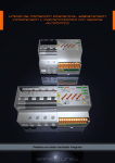
LED (H) Range 1 LED (H) Range 2 LED (H) Range USER’S MANUAL It is essential that the user/installer fully understand the present manual prior to using the unit. Should any doubt arise, please refer to the Authorised Distributor or the Manufacturer All rights reserved. No part of this publication may be reproduced, stored in a retrieval system, or transmitted in any form or by any means electronic, mechanical, recording or photocopying or otherwise without the express prior consent of Safeline, S.L. Whilst every care has been taken to ensure that the information contained herein is correct, no liability can be accepted by Safeline, S.L. for loss, damage or injury caused by any errors in, or omissions from, the information given. Neither is Safeline, S.L. liable for any damage arising from the incorrect use of this information. Safeline, S.L., as also its affiliates, is not liable to the purchaser or to third parties for damages, costs, etc. in which the purchaser or third party may incur as a result of any accident or incorrect use of this product, nor as a result of any unauthorised modification, alteration or repair to same, nor due to non-observance of the operation and maintenance instructions given by Safeline, S.L. With a view, as always, to improving the quality of its products, Safeline reserves the right to modify any characteristic or compliance with norms of the present manual without previous notice. The technical data of these norms is merely informative. Sureline is a trademark of Safeline, S.L. Published in Spain by Safeline, S.L. / 08302-MATARO / Barcelona 6th. Edition (July 2011) 3 LED (H) Range Models DOV707H, OVD706H, RDI705H and OVD106 with built-in reclosure motor-drive: Single-phase includes control module with 2-pole MCB, tripping coil and pertinent measurement toroidal core, depending on version. Three-phase includes control module with4-pole MCB, tripping coil and pertinent measurement toroidal core, depending on version. MODELO TLNBRY - D - A - C - K - V - F - X NOMENCLATURE: MODEL Protection models with built-in reclosure motor-drive. (Substitute MODEL for selected option) - DOV707H (Differential, overvoltage, low voltage and MCB protection. All with automatic reclosure) - OVD706H (Overvoltage, low voltage and MCB protection. All with automatic reclosure) - RDI705H (Differential, low voltage and MCB protection. All with automatic reclosure) - OVD106 (Similar protection to OVD706H) (Only in single-phase version, 8mS cut-off) T - T = Three-phase 4-pole (without T = single-phase 2-pole) L - L =5mS cut-off (without L = 2mS cut-off) N Version with or without sequential reclosure of MCB (Substitute N for selected option) - NR = NO reclosure of MCB (without NR = there IS reclosure of ) B R Version front terminals (Substitute B for selected option) - (No suffix = no relay OUT and no remote IN) - R (Version R-type terminals = relay OUT and no remote IN) - U (Version U-type terminals = relay OUT and remote IN) Number of sequential reclosures of differential and MCB (Substitute R for selected option) - AIT, EAI, VOD, ERT, ETE, RET, TEL Y Protection delay. (Substitute Y for selected option) - No suffix: rapid version D (standard) - M suffix: medium version - S suffix: slow version Sensitivity differential intensity (Substitute D for selected option) - (In 30mA) - (In 300mA) A (standard) MCB intensity (ancillary MCB) (Substitute A for selected option) - 6, 10, 16, 20, 25, 32, 40, 50, 63 A C MCB tripping curve (ancillary MCB) - C, D, B, K K MCB cut-off capacity (ancillary MCB) in accordance with IEC 60947-2. - 10 kA, 15 kA (Substitute C for selected option) (C=standard) (Substitute K for selected option) (10 kA= standard) V Supply voltage (Line Neutral) : 100V (for 100V and 110V ), 120V (for 115V, 120V and 127V), 230V (for 220V, 230V and 240V) - 100V, 120V, 230V (230V= standard) (Substitute V for selected option) F Supply frequency - 50Hz, 60Hz (50 Hz= standard) Differential intesnity measurement toroidal core X - TRDF18 (internal : 18 mm) - TRDF26 (internal : 26 mm) (Substitute F for selected option) (Substitute X for selected option) E.j.: DOV707H TREAI - (In 300mA) - 40A - C - 10KA - 230V - 50HZ - TRDF18 Important Depending on the version of protection unit with built-in reclosure motor-drive (consult identifying label on the side of the unit), there are different protections/alarms and characteristics (please, refer to the corresponding synoptical tables for characteristics of versions) 4 LED (H) Range I N D E X Page INTRODUCTION Description.......................................................................................................................... Technical characteristics ..................................................................................................... Description of display panel................................................................................................. Description of module’s connection terminals...................................................................... 06 06 07 08 Synoptic tables: characteristics of models and versions Metering and protection devices: single-phase 2-pole and three-phase 4-pole.................... 09 PRECAUTIONS / WARNINGS FOR USER / INSTALLER: .................................................................. 11 Positioning of transformer..................................................................................................... 11 Wiring.................................................................................................................................... 11 CHAPTER 1 - Installation Transport and handling ..................................................................................................... 12 Installation............................................................................................................................. 12 Wiring........................................................................................................................................ 12 CHAPTER 2 - Verification and start-up Start-up ................................................................................................................................ Differential Test with rated threshold................................................................................... Autotest: of differential......................................................................................................... Redundant cut-off devices..................................................................................................... 12 12 12 13 CHAPTER 3 - Description of protections Differential protection........................................................................................................... Protection against permanent and transient overvoltage.................................................... Protection against permanent and transient low voltage...................................................... Protection against tripping of MCB. ........................................................................................ Protection against untimely tripping of the differential........................................................... 13 13 14 14 14 CHAPTER 4 - Cut-off. Tripping times Total cut-off time of the MCB................................................................................................. 14 CHAPTER 5 – Mode of Use Remote Control ....................................................................................................................... 14 CHAPTER 6 - Description of basic components Toroidal differential intensity transformer - TRDF18 ................................................... 15 Toroidal differential intensity transformer – TRDF26 ................................................... 15 Ancillary MCB 2 and 4-pole - G.E.. ................................................................................ 15 Very high-speed disconnector (tripping coil) - G.E.............................................................. 15 Ancillary MCB 2 and 4-pole SCHUPA (GEWISS GROUP) ................................................. 15 Very high-speed disconnector (tripping coil) SCHUPA (GEWISS GROUP) ...................... 15 Other ancillary MCB’s and disconnectors ........................................................................... 15 CHAPTER 7 - Trouble-shooting and diagnosis.............................................................................. 15 CHAPTER 8 - Maintenance ..................................................................................................... 16 CHAPTER 9 - Additional options Protection against intense transient overvoltages of short duration ...................................... 16 GUARANTEE Guarantee card .......................................................................................... 17 CIRCUIT DIAGRAMS........................................................................................................................... 19 5 LED (H) Range INTRODUCTION - Description and Characteristics SURELINE incorporates a highly advanced and innovatory technology for protection and metering, with built-in motor-drive in the module itself and protected by user code. An outstanding feature is the very high-speed cut-off (2ms typical in the H range); intelligent automatic reset (conditioned); automatic sequential reset in the event of MCB and differential tripping. SURELINE provides the user with a universal protection which monitors, evaluates, warns and makes automatic decisions. This small, compact unit for 35mm DIN rail is supplied all ready to be installed in a standard enclosure and used in any installation or sector whatsoever. These integrated protections are totally automatic and both these and other characteristics can be extended simply by linking up to other SURELINE modules. - Description Presentation: standard (EN 50 022) enclosure for 35mm DIN rail. This is a compact unit monitored by a microcomputer. Highly stable due to its built-in double process monitor (Watchdog). It withstands permanent and transient overvoltage and low voltage and is capable of protecting multiple lines, both single and three-phase, of up to 63A. The unit provides diverse protections : Differential protection with very high-speed cut-off: Protection against overvoltage by means of very high-speed cut-off Protection against low voltage Moreover, its constant supervision at the supply input permits its automatic, intelligent (conditioned) reset, i.e. it resets solely when the power supply returns to normal. Certain models/versions have input and output Remote Control. Technical characteristics of reclosure module (please, refer to synoptical tables for characteristics of models and versions) Overvoltage protection V Peak Overvoltage protection V Efficient Protection against low voltage Differential protection IN alternating 50 Hz senoidal alternating 50 Hz senoidal rectified preventive cut-off Cut-off time H range Cut-off time HL range Cut-off time HL OVD106 range Delay REMOTE IN Mechanical endurance Safeline reclosure module Mechanical endurance Schupa MCB Mechanical endurance General Electric MCB 2-pole Mechanical endurance General Electric MCB 4-pole Consumption Input voltage (normal system) Input voltage (abnormal system) Transient input voltage Typical precision specs. For module in overvoltage Working temperature 230V AC ± 25 % Dimensions: 2-pole Dimensions: 4-pole Weight : 2-pole Weight : 4-pole Weight of toroidal (TRDF18) Guarantee Design in accordance to norms: Rapid version: > 374 Vpk / Delay >800 microseconds (no suffix) Medium version: > 374 Vpk / Delay >3 milliseconds (model + M suffix) Slow version: > 374 Vpk / Delay >4,2 milliseconds (harsh conditions) (model + S suffix) Rapid version: > 265 V / Delay >800 microseconds (no suffix) Medium version: > 265 V / Delay >250 milliseconds (model +M suffix) Slow version: > 265 V / Delay >500 milliseconds (harsh conditions) (model +S suffix) <180 V (Delay >500ms) 30 mA or 300 mA, rated tripping intensity (acc. version) 1,7 x In, for pulsing senoidal currents (rectified alternating single wave) In the event of power failure 2 to 3ms typical 2- pole (consult “Cut-off. Tripping times”) 5 to 6ms typical 2- pole (consult “Cut-off. Tripping times”) 8 to 9ms typical 2- pole (consult “Cut-off. Tripping times”) 3 ms 100.000 complete manoeuvres (ON/OFF) 20.000 complete manoeuvres (ON/OFF) 20.000 complete manoeuvres (ON/OFF) 15.000 complete manoeuvres (ON/OFF) 1W at 230V 230V AC ± 25 % 50 Hz alternating senoidal up to 450V eff. AC 50 Hz alternating senoidal 1 KV máx. (vp) / 300ms 1 year (2 % ) at 22C 5 C 0 to +40o C. Domestic version -10o to +50o C. Industrial version (I) -25o to +70o C. Extended industrial version (E) 128mm (7 modules) height: 81mm 35mm DIN rail 163mm (9 modules) height: 81mm 35mm DIN rail 900 grs. 1,170 grs. 185 grs. 3 years EN 61008-1 (CEI 1008-1) EN 61008-2-1 (CEI 1008-2) UNE 20-600-77 (CEI-278) Automatic Sequential Reclosures of RCD and MCB Nbr of automatic sequential reclosures RCD In = Ten (3, 3, 3, 3, 3, 3, 3, 3, 3 and 3 mins) Nbr of automatic sequential reclosures MCB = Two (3 and 3 mins Model + suffix ETE, RET, TEL Reset to zero reclosure counter (30 mins Model + suffix ETE, RET, TEL Nbr of automatic sequential reclosures RCD In = Six (3, 6, 12, 30, 60 and 120 mins) Nbr of automatic sequential reclosures MCB = Three (3, 10 and 30 mins) Reset to zero reclosure counter, double the time of last reclosure Model + suffix AIT, EAI, VOD,ERT Model + suffix AIT, EAI, VOD,ERT Model + suffix AIT, EAI, VOD,ERT Customised times and nbr of reclosures (to order, for series) 6 Model + suffix ETE, RET, TEL LED (H) Range Description of display panel DOV707H - DOV707HT - DOV707HL - DOV707HLT 1- Square yellow pushbuttons: vary depending on context: TEST OVERVOLT TEST LOW VOLT (single-phase version) TEST IN TEST OVERVOLT + TEST LOW VOLT = reset 2 – LED’s vary depending on context: Static Green LED (WORKING) : unit is in metering process Static Green LED (L1,L2 and/or L3) : line causing overvoltage (3-phase version) Blinking Red LED (TIMER Reclosure) : countdown in process and when this finishes unit will reclose Blinking Red LED (OVERVOLT) : cut-off due to overvoltage (double blink indicates permanent overvoltage). Blinking Red LED IN 300 mA or 30 mA (acc. version): cut-off due to differential intensity Blinking Red LED (LOW VOLT) : cut-off due to low voltage (double blinking : permanent low voltage). Red LED’s (LOW VOLT, OVERVOLT = BLOCK) lighting up alternatively : unit blocked due to sequential reclosures of RCD or MCB used up. Red LED’s (LOW VOLT, In, OVERVOLT, TIMER) in periodic to-fro sequence : imminent reclosure Static Green LED (WORKING) and Red LED’s (LOW VOLT, In, OVERVOLT) in periodic 3-second sequence : autotest. 3 – Static Red LED’s : anomaly Static Red LED IN 300 mA or 30 mA (acc. version): anomaly in the differential. Due to error in the toroidal core, wiring or differential circuit. Static Red LED (LOW VOLT) : anomaly in the input mains voltage. Due to abnormally low voltage, inferior to 150 V AC. approx. Other Static Red LED’s : anomaly. Do not use unit. Consult technical service. 4 – Sliding ON/OFF switch: ON: normal functioning OFF: disconnection and totally blocked ON + RESET: to start up Description of display panel OVD706H - OVD706HT - OVD706HL - OVD706HLT - OVD106 1- Square yellow pushbuttons: vary depending on context: TEST OVERVOLT TEST LOW VOLT (single-phase version) TEST OVERVOLT + TEST LOW VOLT = reset 2 – LED’s vary depending on context: Static Green LED (WORKING) : unit is in metering process Static Green LED (L1,L2 and/or L3) : line causing overvoltage (3-phase version) Blinking Red LED (TIMER Reclosure) : countdown in process and when this finishes unit will reclose Blinking Red LED (OVERVOLT) : cut-off due to overvoltage (double blink indicates permanent overvoltage). Blinking Red LED (BLOCK) : unit blocked due to sequential reclosures used up. Blinking Red LED (LOW VOLT) : cut-off due to low voltage (double blinking : permanent low voltage). Red LED’s (LOW VOLT, BLOCK, OVERVOLT, TIMER) in periodic to-fro sequence : imminent reclosure Static Green LED (WORKING) and Red LED’s (LOW VOLT, BLOCK, OVERVOLT) in periodic 3-second sequence : autotest. .3 – Static Red LED’s : anomaly Static Red LED (LOW VOLT) : anomaly in the input mains voltage. Due to abnormally low voltage, inferior to 150 V AC. approx. Other Static Red LED’s : anomaly. Do not use unit. Consult technical service. 4 – Sliding ON/OFF switch: ON: normal functioning OFF: disconnection and totally blocked ON + RESET: to start up 7 LED (H) Range Description of display panel RDI705H - RDI705HT - RDI705HL - RDI705HLT 1- Square yellow pushbuttons: vary depending on context: TEST LOW VOLT TEST IN TEST IN + TEST LOW VOLT = reset 2 – LED’s vary depending on context: Static Green LED (WORKING) : unit is in metering process Blinking Red LED (TIMER Reclosure) : countdown in process and when this finishes unit will reclose Blinking Red LED IN 300 mA or 30 mA (acc. version): cut-off due to differential intensity Blinking Red LED (LOW VOLT) : cut-off due to low voltage of module’s line supply (double blinking : permanent low voltage). Blinking Red LED (BLOCK) : unit blocked due to sequential reclosures used up. Red LED’s (LOW VOLT, In, BLOCK, TIMER) in periodic to-fro sequence : imminent reclosure Static Green LED (WORKING) and Red LED’s (LOW VOLT, In, BLOCK) in periodic 3-second sequence : autotest. 3 – Static Red LED’s : anomaly Static Red LED IN 300 mA or 30 mA (acc. version): anomaly in the differential. Due to error in the toroidal core, wiring or differential circuit. Static Red LED (LOW VOLT) : anomaly in the input mains voltage. Due to abnormally low voltage, inferior to 150 V AC. approx. Other Static Red LED’s : anomaly. Do not use unit. Consult technical service. 4 – Sliding ON/OFF switch: ON: normal functioning OFF: disconnection and totally blocked ON + RESET: to start up - Description of module’s connection terminals at rear A CONTROL OUT OUTPUT VERY HIGH SPEED TRIPPING COIL TERMINAL A B CONTROL OUT OUTPUT VERY HIGH SPEED TRIPPING COIL TERMINAL B L1 POWER 230V SUPPLY: PHASE (LINE) 230V + INPUT METERING SENSOR INPUT L1 N POWER 230V SUPPLY: NEUTRAL + INPUT METERING SENSOR INPUT N L2 INPUT 2 INPUT METERING SENSOR L2 (LINE 2) 230V N INPUT 2 INPUT METERING SENSOR N (NEUTRAL) L3 INPUT 3 INPUT METERING SENSOR L3 (LINE 3) 230V N INPUT 3 INPUT METERING SENSOR N (NEUTRAL) - Description of module’s front connection terminals (R-type terminals) I SENSOR 1 G SENSOR 1 T SENSOR 1 1 AUX 2 AUX INPUT 1 DIFFERENTIAL INTENSITY SENSOR COMMON 1, SENSOR AND TEST OUTPUT 1 DIFFERENTIAL INTENSITY TEST VOLTAGE-FREE CONTACT RELAY N/C (CONNECTION N/C WITH 2) VOLTAGE-FREE CONTACT RELAY N/C (CONNECTION N/C WITH 1) (Opens contact between 1 and 2 in the event of alarm and locking) - Description of module’s front connection terminals (U-type terminals) I SENSOR 1 G SENSOR 1 T SENSOR 1 1 AUX. IN-OUT 2 AUX. IN-OUT 3 AUX. IN-OUT 4 AUX. IN-OUT 5 AUX. IN-OUT 6 AUX. IN-OUT 7 AUX. IN-OUT 8 AUX. IN-OUT 9 AUX. IN-OUT INPUT 1 DIFFERENTIAL INTENSITY SENSOR COMMON 1, SENSOR AND TEST OUTPUT 1 DIFFERENTIAL INTENSITY TEST DO NOT CONNECT VOLTAGE-FREE CONTACT RELAY N/C (the ancillary relay is enabled in event of locking) VOLTAGE-FREE CONTACT RELAY COM (the ancillary relay is enabled in event of locking) VOLTAGE-FREE CONTACT RELAY N/A (the ancillary relay is enabled in event of locking) DO NOT CONNECT DO NOT CONNECT DO NOT CONNECT INPUT FOR EXTERNAL POTENTIAL-FREE CONTACT (REMOTE IN) INPUT FOR EXTERNAL POTENTIAL-FREE CONTACT (REMOTE IN) IN ORDER TO ORDER EXTERNALLY A DISCONNECTION, UNLOCKING OR RESET TO ZERO OF THE TRIPPING COUNTER, CLOSE THE CIRCUIT BETWEEN 8 AUX. IN-OUT AND 9 AUX. IN-OUT DURING ONE SECOND AND THEN RE-OPEN. 8 AUX. IN-OUT AND 9 AUX. IN-OUT ARE TO BE CONNECTED AND DISCONNECTED BY MEANS OF A RELAY WITH POTENTIAL-FREE CONTACTS AND WITH AN ISOLATION POTENTIAL OF 4KV - Other options input output remote control, please consult 8 LED (H) Range Synoptic tables: single-phase (2-pole) models 6 to 63A 2-pole DOV707H DOV707HL DOV707HNR DOV707HLNR OVD706H OVD706HL OVD106 OVD706HNR OVD706HLNR 8ms Single-phase 2-pole models ON / OFF command, (all models) Overvoltage protection H range (2ms 2-pole) Overvoltage protection HL range (5ms 2-polos) Automatic intelligent reclosure due to overvoltage Protection against low voltage Automatic intelligent reclosure due to low voltage Protection differential intensity In 30 mA or 300 mA (acc version) Automatic sequential reclosure (differential protection In) MCB protection 10kA, 15kA (acc version) EN 60947-2 Automatic sequential reclosure (MCB protection) Overvoltage test Low voltage test Rated differential intensity test In 30 mA or 300 mA (acc version) Input supply up to 450V AC and 1kV max. (Vpk) / 1 sec. Mechanical endurance reclosure module 100,000 manoeuvres (ON/OFF) Autotest differential + transformer toroidal sensor Automatic/Manual command R-type terminals U-type terminals RDI705H RDI705HL Automatic Sequential Resets RCD and MCB Nbr of automatic sequential reclosures differential In = Ten (3, 3, 3, 3, 3, 3, 3, 3, 3 and 3 mins) Nbr of automatic sequential reclosures MCB = Two (3 and 3 mins) Reset to zero reclosure counter 30 mins Model + suffix ETE, RET, TEL Model + suffix ETE, RET, TEL Model + suffix ETE, RET, TEL Nbr of automatic sequential reclosures differential In = Six (3, 6, 12, 30, 60 and 120 mins) Nbr of automatic sequential reclosures MCB = Three (3, 10 and 30 mins) Reset to zero reclosure counter, double the time of last reclosure Model + suffix AIT, EAI, VOD,ERT Model + suffix AIT, EAI, VOD,ERT Model + suffix AIT, EAI, VOD,ERT Customised times and nbr of reclosures (to order, for series) Single-phase (2-pole) models - 6 to 63A 9 DOV707H 300 mA In DOV707H 30 mA In DOV707HNR 300 mA In DOV707HNR 30 mA In OVD706H OVD706HNR DOV707HL 300 mA In DOV707HL 30 mA In DOV707HLNR 300 mA In DOV707HLNR 30 mA In OVD706HL OVD706HLNR RDI705H 300 mA In RDI705H 30 mA In RDI705HNR 300 mA In RDI705HNR 30 mA In RDI705HL 300 mA In RDI705HL 30 mA In RDI705HLNR 300 mA In RDI705HLNR 30 mA In OVD106 RDI705HNR RDI705HLNR LED (H) Range Synoptic tables: three-phase (4-pole) models 6 to 63A 4-pole Three-phase 4-pole models ON / OFF command, (all models) Overvoltage protection (Line1) (Line2) (Line3) Automatic intelligent reclosure due to overvoltage Low voltage protection (Line1) (Line2) (Line3) Automatic intelligent reclosure due to low voltage Protection differential intensity In 30 mA or 300 mA (acc version) Automatic sequential reclosure (differential protection In) MCB protection 10kA, 15kA (acc version) EN 60947-2 Automatic sequential reclosure (MCB protection) Overvoltage test Low voltage test Rated differential intensity test In 30 mA or 300 mA (acc version) Input supply up to 450V AC and 1kV max. (Vpk) / 1 sec. Mechanical endurance reclosure module 100,000 manoeuvres (ON/OFF) Autotest differential + transformer toroidal sensor Automatic/Manual command R-type terminals U-type terminals DOV707HT DOV707HLT DOV707HTNR DOV707HLTNR OVD706HT OVD706HLT OVD706HTNR OVD706HLTNR RDI705HT RDI705HLT (Line1) (Line1) (Line1) (Line1) RDI705HTNR RDI705HLTNR Automatic Sequential Resets RCD and MCB Nbr of automatic sequential reclosures differential In = Ten (3, 3, 3, 3, 3, 3, 3, 3, 3 and 3 mins) Nbr of automatic sequential reclosures MCB = Two (3 and 3 mins) Reset to zero reclosure counter 30 mins Model + suffix ETE, RET, TEL Model + suffix ETE, RET, TEL Model + suffix ETE, RET, TEL Nbr of automatic sequential reclosures differential In = Six (3, 6, 12, 30, 60 and 120 mins) Nbr of automatic sequential reclosures MCB = Three (3, 10 and 30 mins) Reset to zero reclosure counter, double the time of last reclosure Model + suffix AIT, EAI, VOD,ERT Model + suffix AIT, EAI, VOD,ERT Model + suffix AIT, EAI, VOD,ERT Customised times and nbr of reclosures (to order, for series) Three-phase (4-pole) models – 6 to 63A 10 DOV707HT 300 mA In DOV707HT 30 mA In DOV707HTNR 300 mA In DOV707HTNR 30 mA In OVD706HT OVD706HTNR DOV707HTL 300 mA In DOV707HTL 30 mA In DOV707HTLNR 300 mA In DOV707HTLNR 30 mA In OVD706HTL OVD706HTLNR RDI705HT 300 mA In RDI705HT 30 mA In RDI705HTNR 300 mA In RDI705HTNR 30 mA In RDI705HTL 300 mA In RDI705HTL 30 mA In RDI705HTLNR 300 mA In RDI705HTLNR 30 mA In LED (H) Range PRECAUTIONS / WARNINGS FOR USER / INSTALLER: Despite this unit's being of maximum safety, both from a design and features standpoint, the utmost care must always be taken when using it. It must not be used until its characteristics and mode of operation have been fully understood. Generally speaking, the precautions to be taken with this unit do not differ from those taken with any other piece of electronic equipment connected to the mains. Nevertheless, special attention should be paid to the following: It must be borne in mind that the unit resets the ancillary circuit-breaker automatically and this fact could cause injury to a careless operator or user. In order to avoid this: all up-stream conductors are to be disconnected. (by means of switches, sectionalisers or others.) The mission of the ancillary circuit-breaker element is not that of protecting the circuit-breaker, but rather that of acting as merely as an ancillary switch. The installation should, therefore, be equipped with elements of protection against over-intensity (i.e. circuit-breakers, fuses, etc...) The wiring of the installation must be foreseen for the maximum intensity of the protection elements. Do not apply current nor use the module until it has been correctly installed in a standard enclosure. Do not connect the unit up to voltages other than 230 V AC ± 25%. Do not connect up to installations which may supply intensities of over 15 kA or 10 kA (depending on ancillary MCB) When power supply to the unit is cut off or below minimum (150V AC approx.), o total reset to zero of counters, timers and conditions is generated. Terminals A and B of "CONTROL OUT" must not be short-circuited under any circumstance whatsoever. Should this occur, irreversible damage would be caused to the protection module. Caution: The unit’s connecting terminals are not insulated from the mains Do not expose to liquids or humidity. Do not drop, knock or expose to vibrations.. Do not expose to sources of heat Do not expose to environmental temperatures below 0o, -15o C. Or over 40o, 50o, 70o C (depending on version). Do not expose to magnetic sources or emissions (electric motors and transformers, electro-magnets, etc.). Under no circumstance whatsoever must the unit be opened and the interior manipulated. The safety seals must remain intact. Should they be broken, the correct functioning of the unit could be jeopardised. In the event of any of the above occurring, the authorised technical service must be contacted immediately in order for the unit to be examined. The unit must be completely disconnected from the mains before cleaning. This is to be effected with a soft, dry brush and, if need be, with a slightly damp cloth. The unit must not be reconnected to the mains until having ascertained that it is completely dry. WARNING! This unit must be installed in a standard enclosure, the only part within access of the user being the display and command panel. Its application is restricted to industrial installations. Most important - Positioning of the toroidal transformer and individualized adjustment to its module The differential intensity toroidal core is individually matched and adjusted to the corresponding Sureline module. Therefore, these elements can, under no circumstance whatsoever, be interchanged with others bearing the same reference and from other Sureline modules. Were this toroidal core to be interchanged, the measurement obtained for the differential protection would be erroneous and operation would be abnormal. Only the toroidal transformers supplied for the specific Sureline module can be installed. Each toroidal core indicates the model and serial number of the Sureline module for which it has been specifically matched and adjusted. The toroidal transformer must of necessity be positioned as shown in the “Wiring diagrams”, the direction of the arrow indicating the position with respect to the wiring. The length of the wire connecting the toroidal core to the SURELINE unit must not exceed 30 cms. - Wiring It is of the utmost importance that the correct polarity is ensured upon connection of the SURELINE “L1” and “N” terminals. If this polarity is not respected, the high accuracy is lost originating errors in measurement and abnormal functioning of the protections. A main risk of the unit not functioning correctly could be originated principally by an incorrect wiring up of the connection terminals. It is, therefore, of the utmost importance that this wiring be carried out correctly in accordance with the following protocol: a homologated "male pin" is to be incorporated in the naked core of the stripped pliable conductor. these terminals are placed in the corresponding grooves as far in as they will go ensure that the conductor lead is correctly fixed with the pertinent tightening torque, i.e. there must be no displacement of the terminal nor any damage to the screws on head, thread, fillet or washer, any of which would be to the subsequent detriment of the assemblies and screw connections. The user must carry out the complete protection test periodically as is described in CHAPTER 2. 11 LED (H) Range CHAPTER 1 - Installation Transport and handling This being a highly sophisticated electronic unit, it must be transported and handled with care as per the precautions stipulated in the foregoing section "PRECAUTIONS". Installation The installation must be carried out by responsible, competent and qualified technical personnel once the present manual has been fully understood. The location of the unit must meet the requirements and respect the precautions stipulated in the chapter "PRECAUTIONS", especial attention being paid to those under the heading "Most important". The unit must be installed in a standard single-phase installation, active phase and neutral having a difference of potential of 230 V AC, or a three-phase installation (3 phases + neutral) having a difference of potential from phases to neutral of 230 V AC, and also a protection conductor of operative earth. Moreover, the installation must have, at its main switch panel, appropriate circuit-breakers or fuses and a differential switch. Wiring The unit is fitted with top quality connection terminals. Each terminal has notches to enable easier fixing of the wires and prevent accidental removal. Likewise, the clamping screws have a self-fixing system which avoids their falling out should they work loose. Moreover, the serigraphy identifies the corresponding counter-positioned terminals on the fanning strip. Intuitive identifying colours back up the graphic indications. 1. Connect the POWER L1 terminals to line 1 (phase 1) and POWER N to neutral of the mains line, 230V senoidal alternating current, 50Hz. 2. Connect the remaining terminals as indicated for the chosen configuration. Please, refer to "Circuit diagrams". It is imperative that the wiring of the terminals and the tightening of the screws in the fanning strip be effected correctly. "Circuit diagrams" should be consulted. Should any doubt arise, the manufacturer or authorised distributor should be consulted. CHAPTER 2 - Verification and start-up Start-up Connect all up-stream conductors by means of switches, sectionalisers or others. The reinitiation sequence will automatically be carried out. The ancillary MCB will then reset and the unit will be operative. Carry out all the protection tests. In order to carry out the protection test correctly, the unit must be in the permanent ON position before pressing the test button. To this end, check that the MCB is enabled, otherwise carry out the “start-up” process. Functioning is correct when, once the Test button is pressed the unit cuts off and emits the corresponding diagnosis. When the Test has finished, the unit resets automatically in the case of TEST OVERVOLT and LOW VOLT. In the case of TEST IN 300 mA, the unit will start the countdown process for the reclosure timer. Once this process is concluded, the unit will reset. Should one wish to interrupt the process, one must press “reset”. Differential Test with rated threshold When “TEST IN” is pressed, a defect current is generated in the metering toroidal of the same value as the differential protection, i.e. 30 mA for a 30mA RCD. Other RCD’s, however, stick to the established legal margins and provoke a defect current 250 % superior to the rated value, which is no guarantee that they will actually function at the rated value. Such a high degree of precision and safety requires that the measurement toroidal indicate the direction in which the wiring be passed through This ensures that the defect intensities which circulate throughout the installation are added to the Test intensity rather than deducted. Therefore, when the test is carried out in an installation having zero defect intensities, one will have an optimum test situation. To the contrary, should there be some defect intensity value in the installation, said value would be added to that of the test itself and, in such a case, the test would not be ideal. Autotest: differential The unit automatically tests itself for differential protection every 3 seconds. It checks the constant operativity of: toroidal, wiring of same, amplification, filtering and detection. The performance and its threshold must be checked manually since this involves a cut-off. 12 LED (H) Range When the autotest detects that the differential protection is not valid, it cuts off and diagnoses. In this way, one is totally assured of the constant validity of the extraordinary degree of protection afforded by this differential and the fact that it makes for easy inspection and guarantees that the ruling legislation is complied with at all times. If the autotest detects an anomaly, it cuts off and emits a diagnosis by means of the static “IN”LED lit up. When the anomaly has disappeared, the unit resets. Redundant cut-off devices As a redundant security measure, the unit has a built-in double cut-off device for the ancillary MCB, viz.: Cut-off device #1, by means of a very high-speed tripping coil Cut-off device #2, by means of a built-in motor-drive Moreover, in order to command the double cut-off device, the unit has two independent cut-off circuits, viz.: 1 – Very high-speed cut-off circuit for the MCB by means of a coil. It has its own exclusive built-in energy storage which permits it to disconnect the MCB even when there is no mains supply. 2 - Cut-off circuit by means of a motor. It has its own exclusive built-in energy storage which permits it to disconnect and connect the MCB even when there is no mains supply. CHAPTER 3 - Description of Protections Differential protection When, downstream from the units of the DOV707 and RDI705 ranges, there is a default current to earth which supersedes the threshold corresponding to its value (30mA or 300mA, depending on version), the unit cuts off at very high speed. The reclosure timer immediately enters into a countdown. When this concludes, the unit recloses. If the number of reclosures is used up (depending on version) in a period of time inferior to that indicated on the reset to zero counter (depending on version), the unit will block. cf. Technical characteristics. By Por " default current deriving or leaking to earth” one should understand it as those currents which derive to earth generating a difference of intensities between the active output conductors (phases and neutral). If the leakage or derivation closes the circuit between phases and/or neutral of the live output conductors, there is no difference in intensity between phase and neutral. In this case, the differential protections do not act but then neither would any receiver being supplied from phase to neutral. The functioning of the protection devices against defect currents which derive or leak to earth (differentials) is based on the measurement of the difference in intensity between the live conductors (phase and neutral). Once the pre-established threshold has been exceeded, the cut-off elements of the device come into play. The differential is a standard element of protection. It measures defect currents to earth in order to cut off should this leakage exceed certain pre-established values. For safety reasons, the norm stipulates that a differential must cut off within 50% and 100% of its programmed In value. As a norm, differential manufacturers establish this margin midway in this range, i.e. the threshold is established at 25% below the original programmed In value. The Safeline units are tared in the same way. Over recent years, there has been a steadily growing proliferation of electrical receiver equipment which relies on electronics in order to increase its performance and cut down on energy. For example, tools and domestic appliances with speed regulation, electronics in general, etc... which operate with rectified or pulsing currents. The derivations or defect currents of these rectified or pulsing currents constitute a risk which has been taken into account. Hence, the inclusion of protections against derivations from pulsing currents The SURELINE differential protection differentiates itself from others because of its high precision, very high speed and its constant self-verification, amongst other characteristics. Protection against permanent and transient overvoltage In the event of a permanent or transient overvoltage of a value superior to that programmed (cf. technical characteristics), the unit engineers a very high-speed cut-off via the tripping coil and the motor-drive. The unit withstands permanent overvoltages of 450 V RMS and transient (300ms) 1000V peak voltages. In the event of peak voltages of over 1000 V, the unit protects itself by means of a built-in XXXmA T fuse. Prolonged use in higher-rank voltages is not recommended. The unit will reset automatically when the anomalous condition desists. Whilst there exists an overvoltage, the unit will not reset. 13 LED (H) Range Protection against permanent and transient low voltage In the event of a permanent or transient low voltage of a value inferior to that programmed (cf. technical characteristics), the unit engineers a very high-speed cut-off via the tripping coil and the motor-drive. Whilst there exists a low voltage, the unit will not reset. Protection against tripping of the MCB The SURELINE unit is equipped with an Automatic Sequential Reset of the ancillary MCB (2 or 3 depending on version). Should this act, please refer to technical characteristics. Protection against cut-off of the RCD The SURELINE unit is equipped with an Automatic Sequential Reset of the RCD (6 or 10 depending on version). Should this act, please refer to technical characteristics. CHAPTER 4 - Cut-off. Tripping times. Depending on the model and brand of MCB and coil used, should the protection come into play, cut-off of the 2-pole ancillary MCB is effected in the following typical times. - between 2ms and 3ms, 2 ms models - between 5ms and 6ms, 5 ms models - between 8ms and 9ms, 8 ms models Available upon request, measurement protocol and also the corresponding graphs for the cut-off times of the different models and makes of MCB’s and tripping coils. Total cut-off time of the MCB In order to calculate the total cut-off time in the event of protection acting, the additional programmed delay time of the alarm must be added to that shown on the graphs (typical cut-off time between 2ms and 3ms). Moreover, one must also bear in mind the ionisation effect at the moment of disconnection between the contacts of the ancillary cut-off element (MCB). Even though the starting point of the extinction of the intensity does not vary, the ionisation does prolong the duration. The factors which increase this time are directly proportional to the intensity and the voltage as well as the nature of the load (inductive, capacitive and resistive). CHAPTER 5 - Mode of Use Given the automatic nature of its diverse protections, after having read and fully understood the present manual and having started up the unit, the user may then proceed to connect up the elements of consumption to the protected line and the unit will operate as described in CHAPTERS 2 and 3. Before using the unit, the complete Protection Test must be carried out. If the unit is to be put to permanent use, testing must be done as a matter of routine. Once the test has been completed, should the results not be correct, the unit must not be used under any circumstance whatsoever. The Authorised Technical Service must be contacted at once. Should the user wish to disconnect the line and the unit, the circuit-breaker switch at the main switchboard may be tripped manually (upstream). It must be borne in mind that the unit resets the ancillary MCB automatically and this fact could cause injury to a careless operator or user. In order to avoid this: All up-stream conductors are to be disconnected (by means of switches, sectionalisers or others). REMOTE CONTROL The REMOTE IN and OUT terminals are an invaluable tool which provide characteristics such as: MULTIPOWER, MULTICOMBINATION and INTERACTION with other elements whether these be part of the SURELINE range or others. They provide the user with a modular expansion architecture. If one connects the REMOTE OUT of module A to the REMOTE IN of module B, the former controls and governs the latter. If the connection is made inversely, then module B controls module A. If one connects the OUT and the IN of A to the IN and OUT respectively of B, an interaction is obtained. The REMOTE also enables the SURELINE modules to be governed by programmable automats, by computers or by other means. Likewise, it permits incidents to be recorded in the computer. Another outstanding aspect of the SURELINE philosophy is the possibility of providing an installation with peerless levels of protection without the installation itself having to be modified nor elements substituted despite their being the customary ones. The SURELINE philosophy is based on the simple annexing of protection characteristics in the form of the pertinent SURELINE modules in order to meet any present or future need which may arise. 14 LED (H) Range The following examples should provide the user with some ideas which ought to stimulate his own creativity and imagination: - Linked up to other SURELINE modules - Linked up to other automatic systems (detectors, sensors...) - Linked up to programmable automats, computers, etc. CHAPTER 6 - Description of basic components Differential intensity toroidal transformers TRDF18 and TRDF26 Attention: Individually matched and adjusted to their modules. Do NOT interchange with any other. Toroidal core (high magnetic permeability and low loss). Precision +/- 1%. - internal 18 mm mod. TRDF18 - internal 26 mm mod. TRDF26 - Other dimensions: Consult Safeline Ancillary MCB 2 and 4-pole G.E. Manufacturer: General Electric Type: EP 60 (Breaking capacity 10KA IEC 60947-2 ó 6KA IEC 60898) Type: EP 100 (Breaking capacity 15KA IEC 60947-2 ó 10KA IEC 60898 Curve: C (standard), D, B, K Intensities: 6, 10, 16, 25, 32, 40, 50, 63 A Mechanical endurance MCB 2P and 4P: 20,000 Complete manoeuvres (ON/OFF) For further information, please consult the manufacturer Very high-speed disconnector (tripping coil) Manufacturer: General Electric Type: TELE L-1 CA 24/60V For further information, please consult the manufacturer Ancillary MCB 2 and 4- Pole Manufacturer: SCHUPA (GEWISS GROUP) Type: NLS10 or NLS6 Curve: C Intensities: 16, 25, 32, 40, 50, 63A Cut-off power 10kA or 6kA For further information, please consult the manufacturer Very high-speed disconnector (tripping coil) Manufacturer: SCHUPA (GEWISS GROUP) Type: NLS-F1 12/60V For further information, please consult the manufacturer Other ancillary MCB’s and disconnectors : CHAPTER 7 - Trouble-shooting and diagnosis Consult Authorised Technical Service AUTHORISED TECHNICAL SERVICE: SOLELY BY THE MANUFACTURER 15 Please consult the manufacturer LED (H) Range CHAPTER 8 - Maintenance Before using the unit, the complete Protection Test must be carried out as described in the section “Tests”. If the unit is to be put to permanent use, testing must be done as a matter of routine. Once the protection test has been completed, should the results not be correct, the unit must not be used under any circumstance whatsoever. The Authorised Technical Service must be contacted at once. This is also the case in the event of the eventualities described in the chapter "PRECAUTIONS". Notwithstanding, on a minimal yearly basis, the user must check that the measurements of the electrical parameters of the unit coincide with those stipulated in the technical characteristics, To this end, competent technical personnel at the factory will revise the unit and proceed to calibrate it if need be. The mechanical endurance of the Schupa 2 and 4P MCB is 20,000 complete manoeuvres (ON/OFF). It is recommended that the MCB, the tripping coil and the lever be changed pre-emptively after 10,000 manoeuvres. La mechanical endurance of the General Electric 2P MCB is 20,000 complete manoeuvres (ON/OFF). It is recommended that the MCB, the tripping coil and the lever be changed pre-emptively after 10,000 manoeuvres. La mechanical endurance of the General Electric 4P MCB is 15,000 complete manoeuvres (ON/OFF). ). It is recommended that the MCB, the tripping coil and the lever be changed pre-emptively after 10,000 manoeuvres. (Please, consult manufacturer regarding electrical endurance of external MCB and accessories). CHAPTER 9 - Additional options The new range of protection, metering and registering share the SURELINE philosophy and are extraordinarily versatile. So much so that they permit multiple configurations thanks to their modular expansion architecture not only with present and future SURELINE elements but also with others available on the market. Thus, they complement and are complemented by other characteristics and features regardless of whether or not they are SURELINE's. Please, consult Safeline. Protection against intense transient overvoltages of short duration (nS y S) Thanks to its very high physical cut-off speed and its wide voltage range, which ensure a constant supervision, along with its intelligent reclosure feature, the Sureline units are able to protect a vast gamut of situations. Nevertheless, there exist certain specific situations where there arise powerful but very brief transient overvoltages (S). In such a situation, the Sureline unit should be complemented with a specific protection. This specific protection against extremely powerful and brief (KV/μS) peaks, is to be found in a module form which SAFELINE considers particularly apt as well as being complementary to its own modules. The module in question is based on varistors, surge arresters in this kind of overvoltages. Despite the varistor-based protection system being efficient solely in the event of transient overvoltages of very brief duration (S), it is, nonetheless, the perfect complement for the protections offered by the Sureline unit. The varistor offers a high derivation capacity along with a rapid response time (<25nS), thus diminishing the high values of the fore-mentioned transient overvoltages 16 LED (H) Range GUARANTEE (owner’s copy) SAFELINE, S.L., as a leader in the field of electrical and electronic safety equipment endeavours to maintain an extensive service along with up-dated information to the users of its products. To this end, it is indispensable that the user fills out and returns the present guarantee further to purchase of his SURELINE unit. Period of guarantee: three years as from date of purchase Conditions and application of your SURELINE guarantee: Your SURELINE unit is guaranteed against any defect of manufacture or original components as determined by our Technical Service. Any repair or substitution does not extend the guarantee period. The guarantee covers: Reception of the unit for its repair or servicing. Cost of all components, replacements and labour on original components. The guarantee does NOT cover: Transport Breakdown caused by non-original components or devices. Defects caused by incorrect installation. Damage caused by incorrect usage, or errors arising from repairs and internal manipulation by unauthorised persons. Consumables: fuses, thermal fuses, varistors and labour involved in replacement of same The guarantee is automatically forfeited in the event of:: Breakage or deterioration of the seals of any of the original SURELINE elements. Incorrect usage due to non-observance of the recommendations given in the SURELINE manual. Repair service: All repair service, both within and outside of the guarantee period, is by SAFELINE, S.L. and its Authorised Technical Assistance Services. NOTES (We suggest your noting the serial number of your unit and other information of interest). 17 LED (H) Range GUARANTEE CARD (to be photocopied and returned to Safeline) SURELINE Model..................................................................................................................... Serial Nbr................................................................................................................................ Date of purchase..................................................................................................................... Stamp of establishment where unit purchased (complete address) Purchaser's complete name and address e-mail: (I hereby authorise Safeline to keep me periodically informed) Principal use to which unit is to be put............................................................................................................... Notes.............................................................................................................................................................. GUARANTEE SAFELINE, S.L., as a leader in the field of electrical and electronic safety equipment endeavours to maintain an extensive service along with up-dated information to the users of its products. To this end, it is indispensable that the user fills out and returns the present guarantee further to purchase of his SURELINE unit. Period of guarantee: three years as from date of purchase Conditions and application of your SURELINE guarantee: Your SURELINE unit is guaranteed against any defect of manufacture or original components as determined by our Technical Service. Any repair or substitution does not extend the guarantee period. The guarantee covers: Reception of the unit for its repair or servicing. Cost of all components, replacements and labour on original components. The guarantee does NOT cover: Transport Breakdown caused by non-original components or devices. Defects caused by incorrect installation. Damage caused by incorrect usage, or errors arising from repairs and internal manipulation by unauthorised persons. Consumables: fuses, thermal fuses, varistors and labour involved in replacement of same The guarantee is automatically forfeited in the event of:: Breakage or deterioration of the seals of any of the original SURELINE elements. Incorrect usage due to non-observance of the recommendations given in the SURELINE manual. Repair service: All repair service, both within and outside of the guarantee period, is by SAFELINE, S.L. and its Authorised Technical Assistance Services. 18 LED (H) Range UNIDAD DE PROTECCION AUTORREARMABLE CON MOTOR REARMADOR INTEGRADO. MODELOS DOV707H Y DOV107H (VERSION BORNAS TIPO U) CONFIGURACION MONOFASICA 2 POLOS 6, 10, 16, 20, 25, 32, 40, 50 Y 63A. L ENTRADA 230 V AC N NEUTRO L C1 IMPORTANTE: LA CONEXION DEL NEUTRO AL MAGNETOTERMICO COMO INDICA EL ESQUEMA (BORNA N) N C2 A B N L1 INPUT 1 POWER 230V~ CO NTRO L OU T ! TEST OVER VOLT EPXX Tele L CXX DOV 707H - Consult M anual Protection Unit I N 300 mA RESET WORKING I-ON I-ON M W LO ! LT VO I m A O RV VE O I G T L 1 COM L 2 SEN SOR 1 LT M TI TEST LOW VOLT ER Reclosure BLOCK ON Self Reclosing L N 0 30 TEST OFF 1 ! 2 I N 3 4 5 6 7 8 9 AU XIL IAR Y IN -OU T (C ON SU L T MAN U AL ) N VERSION BORNAS TIPO U CAUTION POSITION TRANSFORMADOR TOROIDAL DE INTENSIDAD DIFERENCIAL TRDF18 T CONSULT MANUAL G I T RDF18 RELE DE SALIDA CONMUTADO LIBRE DE POTECIAL CON FUNCION DE ACTIVACION POR ALARMA Y BLOQUEO BORNA Nº BORNAS AUXILIARY IN-OUT RELE DE SALIDA 5A MAX AC1 2 CONTACTO N/C RELE 3 CONTACTO COMUN RELE 2 3 4 4 CONTACTO N/O RELE ENTRADAS PARA CONTACTO EXTERNO LIBRE DE POTENCIAL CON FUNCION DE DESCONEXION, DESBLOQUEO Y PUESTA A CERO DE LA CUENTA DE DISPAROS BORNA Nº BORNAS AUXILIARY IN-OUT ENTRADAS REM OTE IN 8 ENTRADA REMOTE IN 9 ENTRADA REMOTE IN L BORNA BORNAS NO CONECTAR 1 BORNA NO CONECTAR 5 BORNA NO CONECTAR 6 BORNA NO CONECTAR 7 BORNA NO CONECTAR SALIDA 230 V AC N TRDF18: PASAR LOS CONDUCTORES FASE (L1) Y NEUTRO (N) POR EL ORIFICIO DEL TRANSFORMADOR TOROIDAL INDIVIDUALMENTE EMPAREJADO Y AJUSTADO PARA SU MODULO NO INTERCAMBIAR Y POSICIONARLO SEGUN SENTIDO FLECHA ! 19 CONSULTAR MANUAL DE INSTRUCCIONES RELE LED (H) Range UNIDAD DE PROTECCION AUTORREARMABLE CON MOTOR REARMADOR INTEGRADO. MODELOS DOV707H Y DOV107H (VERSION BORNAS TIPO R) CONFIGURACION MONOFASICA 2 POLOS 6, 10, 16, 20, 25, 32, 40, 50 Y 63A. L ENTRADA 230 V AC N NEUTRO L C1 IMPORTANTE: LA CONEXION DEL NEUTRO AL MAGNETOTERMICO COMO INDICA EL ESQUEMA (BORNA N) N C2 A B N L1 INPUT 1 POWER 230V~ CO N T RO L OU T ! EPXX Tele L CXX DOV 707H - Consult M anual Protection Unit I N 300 mA RESET TEST OVER VOLT WORKING I-ON I-ON LT M W VO LO ! I SEN SO R 1 L CAUTION POSITION TRANSFORMADOR TOROIDAL DE INTENSIDAD DIFERENCIAL TRDF18 T A LT O RV VE O G T M TI ER TEST LOW VOLT Reclosure TEST OFF I N AUX. ! 1 2 N CONSULT MANUAL G m BLOCK ON Self Reclosing I N 0 30 I VERSION BORNAS TIPO R RELE DE SALIDA LIBRE DE POTECIAL CON FUNCION DE ACTIVACION POR BLOQUEO T RDF18 BORNA Nº AUX. RELE DE SALIDA 1A M AX AC1 BORNA NO CONECTAR 1 CONTACTO N/C RELE 2 CONTACTO COMUN RELE 1 BORNA Nº 2 Y 3, CONTACTO AUXILIAR NORMALMENTE CERRADO SE ABRE EN CASO DE ALARMA Y BLOQUEO L SALIDA 230 V AC N TRDF18: PASAR LOS CONDUCTORES FASE (L1) Y NEUTRO (N) POR EL ORIFICIO DEL TRANSFORMADOR TOROIDAL INDIVIDUALMENTE EMPAREJADO Y AJUSTADO PARA SU MODULO NO INTERCAMBIAR Y POSICIONARLO SEGUN SENTIDO FLECHA ! 20 CONSULTAR MANUAL DE INSTRUCCIONES 2 RELE LED (H) Range UNIDAD DE PROTECCION AUTORREARMABLE CON MOTOR REARMADOR INTEGRADO. MODELOS DOV707HT Y DOV107HT (VERSION BORNAS TIPO U) ENTRADA CONFIGURACION TRIFASICA 4 POLOS 6, 10, 16, 20, 25, 32, 40 Y 63A. N NEUTRO L1 ENTRADA 230 V AC ENTRE NEUTRO Y LINEAS (L1, L2, L3) L2 ENTRADA 400 V AC ENTRE LINEAS (L1 Y L2, L1 Y L3, L2 Y L3) L3 L3 IMPORTANTE: LA CONEXION DEL NEUTRO AL MAGNETOTERMICO COMO INDICA EL ESQUEMA (BORNA N) C1 L2 L1 N C2 A B N CO NT RO L O UT ! L1 N INPUT 1 PO W ER 230V~ L2 L3 INPUT 3 L1 WORKING EPXX Tele L CXX N INPUT 2 DOV 707HT - Consult M anual Protection Unit I N 300 mA L2 L3 I-ON I-ON I-ON I-ON M W LO ! LT VO I G T L1 COM L 2 SEN SOR 1 L2 L1 m A LT O RV VE O M TI ER Reclosure BLOCK ON Self Reclosing L3 N I 0 30 TEST OVER VOLT RESET TEST OFF 1 ! 2 I N 3 4 5 6 7 8 9 AU XIL IAR Y IN -OU T (C ON SU L T MAN U AL) N VERSION BORNAS TIPO U CAUTION POSITION TRANSFORMADOR TOROIDAL DE INTENSIDAD DIFERENCIAL TRDF18 ó TRDF26 T CONSULT MANUAL G I T RDF18 RELE DE SALIDA CONM UTADO LIBRE DE POTECIAL CON FUNCION DE ACTIVACION POR ALARM A Y BLOQUEO BORNA Nº BORNAS AUXILIARY IN-OUT RELE DE SALIDA 5A M AX AC1 2 CONTACTO N/C RELE 3 CONTACTO COM UN RELE 2 3 4 RELE 4 CONTACTO N/O RELE ENTRADAS PARA CONTACTO EXTERNO LIBRE DE POTENCIAL CON FUNCION DE DESCONEXION, DESBLOQUEO Y PUESTA A CERO DE LA CUENTA DE DISPAROS BORNA Nº SALIDA L3 BORNAS AUXILIARY IN-OUT ENTRADAS REM OTE IN 8 ENTRADA REMOTE IN 9 ENTRADA REMOTE IN L2 L1 N TRDF18 ó TRDF26: PASAR LOS CONDUCTORES L1, L2, L3 Y NEUTRO BORNA BORNAS NO CONECTAR 1 BORNA NO CONECTAR 5 BORNA NO CONECTAR 6 BORNA NO CONECTAR 7 BORNA NO CONECTAR POR EL ORIFICIO DEL TRANSFORMADOR TOROIDAL INDIVIDUALMENTE EMPAREJADO Y AJUSTADO PARA SU MODULO NO INTERCAMBIAR Y POSICIONARLO SEGUN SENTIDO FLECHA ! 21 CONSULTAR MANUAL DE INSTRUCCIONES LED (H) Range UNIDAD DE PROTECCION AUTORREARMABLE CON MOTOR REARMADOR INTEGRADO. MODELOS DOV707HT Y DOV107HT (VERSION BORNAS TIPO R) ENTRADA CONFIGURACION TRIFASICA 4 POLOS 6, 10, 16, 20, 25, 32, 40 Y 63A. N NEUTRO L1 ENTRADA 230 V AC ENTRE NEUTRO Y LINEAS (L1, L2, L3) L2 ENTRADA 400 V AC ENTRE LINEAS (L1 Y L2, L1 Y L3, L2 Y L3) L3 L3 IMPORTANTE: LA CONEXION DEL NEUTRO AL MAGNETOTERMICO COMO INDICA EL ESQUEMA (BORNA N) C1 L2 L1 N C2 A B N CO NT RO L O UT ! L1 N INPUT 1 PO W ER 230V~ L2 L3 INPUT 3 WORKING EPXX Tele L CXX N INPUT 2 DOV 707HT - Consult M anual Protection Unit I N 300 mA L1 L2 L3 I-ON I-ON I-ON I-ON M LO W ! LT VO I SENSO R 1 I L2 CAUTION POSITION TRANSFORMADOR TOROIDAL DE INTENSIDAD DIFERENCIAL TRDF18 ó TRDF26 T L1 A O RV VE O G T LT M TI Reclosure ER TEST OVER VOLT RESET TEST OFF I N AU X. ! 1 2 N CONSULT MANUAL G m BLOCK ON Self Reclosing L3 N 0 30 I T RDF18 VERSION BORNAS TIPO R RELE DE SALIDA LIBRE DE POTECIAL CON FUNCION DE ACTIVACION POR BLOQUEO BORNA Nº AUX. RELE DE SALIDA 1A MAX AC1 BORNA NO CONECTAR 1 CONTACTO N/C RELE 2 CONTACTO COMUN RELE 1 BORNA Nº 2 Y 3, CONTACTO AUXILIAR NORMALMENTE CERRADO SE ABRE EN CASO DE ALARMA Y BLOQUEO SALIDA L3 L2 L1 N TRDF18 ó TRDF26: PASAR LOS CONDUCTORES L1, L2, L3 Y NEUTRO POR EL ORIFICIO DEL TRANSFORMADOR TOROIDAL INDIVIDUALMENTE EMPAREJADO Y AJUSTADO PARA SU MODULO NO INTERCAMBIAR Y POSICIONARLO SEGUN SENTIDO FLECHA ! 22 CONSULTAR MANUAL DE INSTRUCCIONES 2 RELE LED (H) Range UNIDAD DE PROTECCION AUTORREARMABLE CON MOTOR REARMADOR INTEGRADO. MODELOS OVD706H Y OVD106H (VERSION BORNAS TIPO U) CONFIGURACION MONOFASICA 2 POLOS 6, 10, 16, 20, 25, 32, 40, 50 Y 63A. L ENTRADA 230 V AC N NEUTRO L IMPORTANTE: LA CONEXION DEL NEUTRO AL MAGNETOTERMICO COMO INDICA EL ESQUEMA (BORNA N) C1 N C2 A B N Tele L L1 INPUT 1 POWER 2 30V~ CO NT RO L OU T ! TEST OVER VOLT EPXX CXX OVD 706H - Consult M anual Protection Unit RESET WORKING I-ON I-ON M W LO LT VO 1 ! 2 ON Self Reclosing I G T L 1 COM L 2 SEN SOR 1 L O BL LT O RV ER VE M O TI CK 3 TEST LOW VOLT Reclosure OFF 1 2 3 4 5 6 7 8 9 AU XIL IAR Y IN -OU T (C ON SU L T MAN U AL ) ! N VERSION BORNAS TIPO U RELE DE SALIDA CONM UTADO LIBRE DE POTECIAL CON FUNCION DE ACTIVACION POR ALARMA Y BLOQUEO BORNA Nº BORNAS AUXILIARY IN-OUT RELE DE SALIDA 5A MAX AC1 2 CONTACTO N/C RELE 3 CONTACTO COM UN RELE 2 3 4 RELE 4 L ENTRADAS PARA CONTACTO EXTERNO LIBRE DE POTENCIAL CON FUNCION DE DESCONEXION, DESBLOQUEO Y PUESTA A CERO DE LA CUENTA DE DISPAROS BORNA Nº SALIDA 230 V AC N ! 23 CONTACTO N/O RELE BORNAS AUXILIARY IN-OUT ENTRADAS REM OTE IN 8 ENTRADA REM OTE IN 9 ENTRADA REM OTE IN BORNA BORNAS NO CONECTAR I BORNA NO CONECTAR G BORNA NO CONECTAR T BORNA NO CONECTAR 1 BORNA NO CONECTAR 5 BORNA NO CONECTAR 6 BORNA NO CONECTAR 7 BORNA NO CONECTAR CONSULTAR MANUAL DE INSTRUCCIONES LED (H) Range UNIDAD DE PROTECCION AUTORREARMABLE CON MOTOR REARMADOR INTEGRADO. MODELOS OVD706H Y OVD106H (VERSION BORNAS TIPO R) CONFIGURACION MONOFASICA 2 POLOS 6, 10, 16, 20, 25, 32, 40, 50 Y 63A. L ENTRADA 230 V AC N NEUTRO L IMPORTANTE: LA CONEXION DEL NEUTRO AL MAGNETOTERMICO COMO INDICA EL ESQUEMA (BORNA N) C1 N C2 A B N CO NT RO L OU T ! Tele L L1 INPUT 1 POWER 230V~ EPXX CXX OVD 706H - Consult M anual Protection Unit RESET TEST OVER VOLT WORKING I-ON I-ON M W LO LT VO 1 ! 2 ON Self Reclosing SENSO R 1 I L G CK O BL T O 3 O RV VE LT M TI ER TEST LOW VOLT Reclosure OFF AUX. ! 1 2 N VERSION BORNAS TIPO R RELE DE SALIDA LIBRE DE POTECIAL CON FUNCION DE ACTIVACION POR ALARM A Y BLOQUEO BORNA Nº AUX. RELE DE SALIDA 1A MAX AC1 BORNA NO CONECTAR L 1 CONTACTO N/C RELE 2 CONTACTO COM UN RELE BORNA Nº 2 Y 3, CONTACTO AUXILIAR NORMALMENTE CERRADO SE ABRE EN CASO DE BLOQUEO SALIDA 230 V AC N ! 24 1 BORNA BORNAS NO CONECTAR I BORNA NO CONECTAR G BORNA NO CONECTAR T BORNA NO CONECTAR CONSULTAR MANUAL DE INSTRUCCIONES 2 RELE LED (H) Range UNIDAD DE PROTECCION AUTORREARMABLE CON MOTOR REARMADOR INTEGRADO. MODELOS OVD706HT Y OVD106HT (VERSION BORNAS TIPO U) ENTRADA CONFIGURACION TRIFASICA 4 POLOS 6, 10, 16, 20, 25, 32, 40, 50 Y 63A. N NEUTRO L1 ENTRADA 230 V AC ENTRE NEUTRO Y LINEAS (L1, L2, L3) L2 ENTRADA 400 V AC ENTRE LINEAS (L1 Y L2, L1 Y L3, L2 Y L3) L3 L3 IMPORTANTE: LA CONEXION DEL NEUTRO AL MAGNETOTERMICO COMO INDICA EL ESQUEMA (BORNA N) C1 L2 L1 N C2 A B N CO NTRO L O UT ! L1 INPUT 1 PO W ER 230V~ N L2 L3 INPUT 3 WORKING EPXX Tele L CXX N INPUT 2 L1 OVD 706HT - Consult M anual Prot ect ion Unit L2 L3 I-ON I-ON I-ON I-ON M W LO LT VO 1 ! 2 ON Self Reclosing I G T L 1 COM L 2 SEN SOR 1 L3 L2 L1 CK O BL O RV VE O 3 LT M TI ER Reclosure TEST OVER VOLT RESET TEST LOW VOLT OFF 1 2 3 4 5 6 7 8 9 AU XIL IAR Y IN -OU T (CON SU L T M AN U AL ) ! N VERSION BORNAS TIPO U RELE DE SALIDA CONMUTADO LIBRE DE POTECIAL CON FUNCION DE ACTIVACION POR ALARMA Y BLOQUEO BORNA Nº BORNAS AUXILIARY IN-OUT RELE DE SALIDA 5A MAX AC1 2 CONTACTO N/C RELE 3 CONTACTO COMUN RELE 2 3 4 4 CONTACTO N/O RELE ENTRADAS PARA CONTACTO EXTERNO LIBRE DE POTENCIAL CON FUNCION DE DESCONEXION, DESBLOQUEO Y PUESTA A CERO DE LA CUENTA DE DISPAROS BORNA Nº SALIDA L3 L2 L1 N ! 25 BORNAS AUXILIARY IN-OUT ENTRADAS REM OTE IN 8 ENTRADA REMOTE IN 9 ENTRADA REMOTE IN BORNA BORNAS NO CONECTAR I BORNA NO CONECTAR G BORNA NO CONECTAR T BORNA NO CONECTAR 1 BORNA NO CONECTAR 5 BORNA NO CONECTAR 6 BORNA NO CONECTAR 7 BORNA NO CONECTAR CONSULTAR MANUAL DE INSTRUCCIONES RELE LED (H) Range UNIDAD DE PROTECCION AUTORREARMABLE CON MOTOR REARMADOR INTEGRADO. MODELOS OVD706HT Y OVD106HT (VERSION BORNAS TIPO R) ENTRADA CONFIGURACION TRIFASICA 4 POLOS 6, 10, 16, 20, 25, 32, 40, 50 Y 63A. N NEUTRO L1 ENTRADA 230 V AC ENTRE NEUTRO Y LINEAS (L1, L2, L3) L2 ENTRADA 400 V AC ENTRE LINEAS (L1 Y L2, L1 Y L3, L2 Y L3) L3 L3 IMPORTANTE: LA CONEXION DEL NEUTRO AL MAGNETOTERMICO COMO INDICA EL ESQUEMA (BORNA N) C1 L2 L1 N C2 A B N Tele L L1 INPUT 1 PO WER 230V~ CO NT ROL O UT ! N N L3 INPUT 3 WORKING EPXX CXX L2 INPUT 2 OVD 706HT - Consult M anual Protection Unit L1 L2 L3 I-ON I-ON I-ON I-ON LT M W 1 ! 2 SENSO R 1 I L3 L2 L1 O BL LO ON Self Reclosing G T LT O RV VE O CK VO 3 M TI Reclosure ER TEST OVER VOLT RESET TEST LOW VOLT OFF AUX. ! 1 2 N VERSION BORNAS TIPO R RELE DE SALIDA LIBRE DE POTECIAL CON FUNCION DE ACTIVACION POR ALARM A Y BLOQUEO BORNA Nº AUX. RELE DE SALIDA 1A M AX AC1 BORNA NO CONECTAR 1 CONTACTO N/C RELE 2 CONTACTO COMUN RELE 1 BORNA Nº 2 Y 3, CONTACTO AUXILIAR NORMALMENTE CERRADO SE ABRE EN CASO DE BLOQUEO SALIDA L3 L2 BORNAS NO CONECTAR I BORNA NO CONECTAR G BORNA NO CONECTAR T BORNA NO CONECTAR L1 N ! 26 BORNA CONSULTAR MANUAL DE INSTRUCCIONES 2 RELE LED (H) Range UNIDAD DE PROTECCION AUTORREARMABLE CON MOTOR REARMADOR INTEGRADO. MODELOS RDI705H Y RDI105H (VERSION BORNAS TIPO U) CONFIGURACION MONOFASICA 2 POLOS 6, 10, 16, 20, 25, 32, 40, 50 Y 63A. L ENTRADA 230 V AC N NEUTRO L C1 IMPORTANTE: LA CONEXION DEL NEUTRO AL MAGNETOTERMICO COMO INDICA EL ESQUEMA (BORNA N) N C2 A B N L1 INPUT 1 POWER 230V~ CO NT RO L OU T ! EPXX Tele L CXX RDI 705H - Consult M anual Protection Unit I N 300 mA 1 ! I G T L 1 COM L 2 SEN SOR 1 ER CK TEST LOW VOLT I TI M BL O 30 0 N 2 ON Self Reclosing L m VO LT W I-ON LO I-ON A WORKING M 3 Reclosure RESET TEST OFF 1 ! 2 I N 3 4 5 6 7 8 9 AU XILIAR Y IN -OU T (C ON SU L T MAN U AL ) N VERSION BORNAS TIPO U CAUTION POSITION TRANSFORMADOR TOROIDAL DE INTENSIDAD DIFERENCIAL TRDF18 T CONSULT MANUAL G I T RDF18 RELE DE SALIDA CONMUTADO LIBRE DE POTECIAL CON FUNCION DE ACTIVACION POR ALARM A Y BLOQUEO BORNA Nº BORNAS AUXILIARY IN-OUT RELE DE SALIDA 5A M AX AC1 2 CONTACTO N/C RELE 3 CONTACTO COM UN RELE 2 3 4 RELE 4 CONTACTO N/O RELE ENTRADAS PARA CONTACTO EXTERNO LIBRE DE POTENCIAL CON FUNCION DE DESCONEXION, DESBLOQUEO Y PUESTA A CERO DE LA CUENTA DE DISPAROS BORNA Nº BORNAS AUXILIARY IN-OUT ENTRADAS REM OTE IN 8 ENTRADA REM OTE IN 9 ENTRADA REM OTE IN L BORNA BORNAS NO CONECTAR 1 BORNA NO CONECTAR 5 BORNA NO CONECTAR 6 BORNA NO CONECTAR 7 BORNA NO CONECTAR SALIDA 230 V AC N TRDF18: PASAR LOS CONDUCTORES FASE (L1) Y NEUTRO (N) POR EL ORIFICIO DEL TRANSFORMADOR TOROIDAL INDIVIDUALMENTE EMPAREJADO Y AJUSTADO PARA SU MODULO NO INTERCAMBIAR Y POSICIONARLO SEGUN SENTIDO FLECHA ! 27 CONSULTAR MANUAL DE INSTRUCCIONES LED (H) Range UNIDAD DE PROTECCION AUTORREARMABLE CON MOTOR REARMADOR INTEGRADO. MODELOS RDI705H Y RDI105H (VERSION BORNAS TIPO R) CONFIGURACION MONOFASICA 2 POLOS 6, 10, 16, 20, 25, 32, 40, 50 Y 63A. L ENTRADA 230 V AC N NEUTRO L C1 IMPORTANTE: LA CONEXION DEL NEUTRO AL MAGNETOTERMICO COMO INDICA EL ESQUEMA (BORNA N) N C2 A B N C O NT RO L OU T ! L1 INPUT 1 POWER 230V~ EPXX Tele L CXX RDI 705H - Consult M anual Protection Unit I N 300 mA WORKING I-ON I-ON M W LO VO I 1 ! SENSO R 1 L CAUTION POSITION TRANSFORMADOR TOROIDAL DE INTENSIDAD DIFERENCIAL TRDF18 T T m A CK O BL 3 M TI Reclosure ER TEST LOW VOLT RESET TEST OFF I N AUX. ! 1 2 N CONSULT MANUAL G G N 0 30 2 ON Self Reclosing I LT I VERSION BORNAS TIPO R RELE DE SALIDA LIBRE DE POTECIAL CON FUNCION DE ACTIVACION POR BLOQUEO T RDF18 BORNA Nº AUX. RELE DE SALIDA 1A MAX AC1 BORNA NO CONECTAR 1 CONTACTO N/C RELE 2 CONTACTO COMUN RELE 1 BORNA Nº 2 Y 3, CONTACTO AUXILIAR NORMALMENTE CERRADO SE ABRE EN CASO DE ALARMA Y BLOQUEO L SALIDA 230 V AC N TRDF18: PASAR LOS CONDUCTORES FASE (L1) Y NEUTRO (N) POR EL ORIFICIO DEL TRANSFORMADOR TOROIDAL INDIVIDUALMENTE EMPAREJADO Y AJUSTADO PARA SU MODULO NO INTERCAMBIAR Y POSICIONARLO SEGUN SENTIDO FLECHA ! 28 CONSULTAR MANUAL DE INSTRUCCIONES 2 RELE LED (H) Range UNIDAD DE PROTECCION AUTORREARMABLE CON MOTOR REARMADOR INTEGRADO. MODELOS RDI705HT Y RDI105HT (VERSION BORNAS TIPO U) ENTRADA CONFIGURACION TRIFASICA 4 POLOS 6, 10, 16, 20, 25, 32, 40 Y 63A. N NEUTRO L1 ENTRADA 230 V AC ENTRE NEUTRO Y LINEAS (L1, L2, L3) L2 ENTRADA 400 V AC ENTRE LINEAS (L1 Y L2, L1 Y L3, L2 Y L3) L3 L3 IMPORTANTE: LA CONEXION DEL NEUTRO AL MAGNETOTERMICO COMO INDICA EL ESQUEMA (BORNA N) C1 L2 L1 N C2 A B N L1 INPUT 1 POWER 230V~ CO NT RO L OU T ! EPXX Tele L CXX RDI 705H - Consult M anual Protection Unit I N 300 mA WORKING I-ON I-ON I-ON I-ON M W LO LT VO 1 ! G T L 1 COM L 2 SEN SOR 1 L3 L2 L1 N 2 ON Self Reclosing I I 0 30 m A O BL 3 CK M TI ER Reclosure TEST LOW VOLT RESET TEST OFF 1 ! 2 I N 3 4 5 6 7 8 9 AU XILIAR Y IN -OU T (C ON SU L T MAN U AL ) N VERSION BORNAS TIPO U CAUTION POSITION TRANSFORMADOR TOROIDAL DE INTENSIDAD DIFERENCIAL TRDF18 ó TRDF26 T CONSULT MANUAL G I T RDF18 RELE DE SALIDA CONM UTADO LIBRE DE POTECIAL CON FUNCION DE ACTIVACION POR ALARM A Y BLOQUEO BORNA Nº BORNAS AUXILIARY IN-OUT RELE DE SALIDA 5A M AX AC1 2 CONTACTO N/C RELE 3 CONTACTO COM UN RELE 4 2 3 CONTACTO N/O RELE ENTRADAS PARA CONTACTO EXTERNO LIBRE DE POTENCIAL CON FUNCION DE DESCONEXION, DESBLOQUEO Y PUESTA A CERO DE LA CUENTA DE DISPAROS BORNA Nº SALIDA L3 BORNAS AUXILIARY IN-OUT ENTRADAS REM OTE IN 8 ENTRADA REMOTE IN 9 ENTRADA REMOTE IN L2 L1 N TRDF18 ó TRDF26: PASAR LOS CONDUCTORES L1, L2, L3 Y NEUTRO BORNA BORNAS NO CONECTAR 1 BORNA NO CONECTAR 5 BORNA NO CONECTAR 6 BORNA NO CONECTAR 7 BORNA NO CONECTAR POR EL ORIFICIO DEL TRANSFORMADOR TOROIDAL INDIVIDUALMENTE EMPAREJADO Y AJUSTADO PARA SU MODULO NO INTERCAMBIAR Y POSICIONARLO SEGUN SENTIDO FLECHA ! 29 CONSULTAR MANUAL DE INSTRUCCIONES 4 RELE LED (H) Range UNIDAD DE PROTECCION AUTORREARMABLE CON MOTOR REARMADOR INTEGRADO. MODELOS RDI705HT Y RDI105HT (VERSION BORNAS TIPO R) ENTRADA CONFIGURACION TRIFASICA 4 POLOS 6, 10, 16, 20, 25, 32, 40 Y 63A. N NEUTRO L1 ENTRADA 230 V AC ENTRE NEUTRO Y LINEAS (L1, L2, L3) L2 ENTRADA 400 V AC ENTRE LINEAS (L1 Y L2, L1 Y L3, L2 Y L3) L3 L3 IMPORTANTE: LA CONEXION DEL NEUTRO AL MAGNETOTERMICO COMO INDICA EL ESQUEMA (BORNA N) C1 L2 L1 N C2 A B N L1 INPUT 1 POWER 230V~ CO NT RO L OU T ! EPXX Tele L CXX RDI 705H - Consult M anual Protection Unit I N 300 mA WORKING I-ON I-ON I-ON I-ON M W LO LT VO I 1 ! 2 ON Self Reclosing SENSO R 1 I L3 L2 CAUTION POSITION TRANSFORMADOR TOROIDAL DE INTENSIDAD DIFERENCIAL TRDF18 ó TRDF26 T L1 T m A O BL 3 CK M TI Reclosure ER TEST LOW VOLT RESET TEST OFF I N AUX. ! 1 2 N CONSULT MANUAL G G N 0 30 I T RDF18 VERSION BORNAS TIPO R RELE DE SALIDA LIBRE DE POTECIAL CON FUNCION DE ACTIVACION POR BLOQUEO BORNA Nº AUX. RELE DE SALIDA 1A MAX AC1 BORNA NO CONECTAR 1 CONTACTO N/C RELE 2 CONTACTO COM UN RELE 1 BORNA Nº 2 Y 3, CONTACTO AUXILIAR NORMALMENTE CERRADO SE ABRE EN CASO DE ALARMA Y BLOQUEO SALIDA L3 L2 L1 N TRDF18 ó TRDF26: PASAR LOS CONDUCTORES L1, L2, L3 Y NEUTRO POR EL ORIFICIO DEL TRANSFORMADOR TOROIDAL INDIVIDUALMENTE EMPAREJADO Y AJUSTADO PARA SU MODULO NO INTERCAMBIAR Y POSICIONARLO SEGUN SENTIDO FLECHA ! 30 CONSULTAR MANUAL DE INSTRUCCIONES 2 RELE 41 05. 01 81 Ø 31 70.80 50.50 TRDF18 TRIT18 DIMENSIONES TRANSFORMADORES TOROIDALES: 52.60 LED (H) Range 07. 03 32 05. 01 62 Ø 90.40 30 70 80 Ø 4.20 TRDF26 DIMENSIONES TRANSFORMADOR TOROIDAL: 76 LED (H) Range 03. 03 67 01 41 LED (H) Range SAFELINE, S.L. Safeline Building Cooperativa, 24 E 08302 MATARO (Barcelona) SPAIN www.safeline.es [email protected] Commercial R+D Factory Administration T. +34 93 8841820 T. +34 93 8841821 [email protected] T. +34 93 7630801 F. +34 93 7630090 [email protected] T. +34 93 7630671 F. +34 93 7630090 [email protected] Made in EU 33