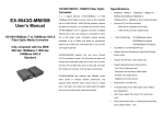
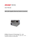
1
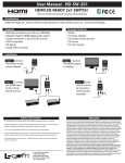
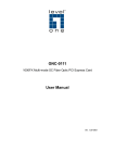
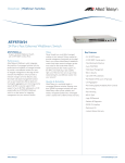
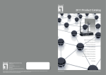
LC-MCC14AA
14 Slot Unmanaged Media Converter Chassis
User’s Manual
Please read this before installing your product.
Product Description
The LC-MCC14AA 14-slot media converter chassis supports plug-and-play installation of any stand-alone L-com LCMCG Series 10/100/1000TX to 1000FX media converters. All chassis models can be mounted into a 2U (3.5 inch) rack
space on a standard 19 inch rack.
14 slot rack-mounted chassis Fig. 1
Packing List
The box should contain the following items:
• (1) LC-MCC14AA 14-Slot Media Converter Chassis with dual power supplies installed
• (2) AC Power Cords
• (14) Media Converter brackets (for securing to chassis)
• This User’s Manual
Please notify L-com immediately if any items are missing or damaged.
Product Overview
L-com’s LC-MCC14AA 14-Slot Media Converter Chassis provides real-time power backup. Each chassis comes equipped
right out of the box with dual redundant power supplies. The LC-MCC14AA chassis is compatible with any of the L-com
LC-MCG series media converters (see compatible media converter chart on page 4).
The Media Converters can be hot-swapped to change configuration requirements or replace malfunctioning units without
the need to power down the chassis. Both power supplies feature status LED’s (Green = Functioning) (Red = Problem) to
help you quickly identify which unit is experiencing a problem. There is also an audible alarm that sounds to alert you to
the situation. The Dual power supplies are also truly hot-swappable, allowing you to replace a bad unit while the second
unit continues to power the chassis and installed converters, minimizing network disruptions. L-com also offers
replacement power supplies so that you can keep an emergency spare on hand or be able to quickly order a replacement in
the event you need one.
.
L-COM INC. 45 BEECHWOOD DRIVE NORTH ANDOVER MA 01845
WWW.L-COM.COM E-MAIL: [email protected] PHONE: 1-800-343-1455 FAX: 1-978-689-9484
© L-com Inc. All Rights Reserved. L-com Global Connectivity and the L-com logo are registered marks.
Installation of the Chassis and Media Converters
1. Mount the LC-MCC14AA chassis into a standard 19 inch rack cabinet or enclosure utilizing the integrated rack
mount ears. Secure the chassis with 4 rack screws (not included) that typically come with 19 inch rack products.
2. Plug the provided power cords into each of the power supplies then plug them into the nearest AC outlet
3. Switch on both of the power supplies to verify you have power available and confirm that the supplies are
functioning correctly. The Green LED and cooling fan should turn on if functioning correctly.
Note: It is normal for the audible alert to sound briefly when first turning on the power supply units
4. Remove the blank plates from the face of the chassis as needed for the quantity of media converters you are
planning to install.
(The blank plates come in 2 sizes the first two cover one slot each and the remaining 3 plates cover 4 slots each)
5. Locate the package of media converter retention brackets included with the chassis
6. Before installing the bracket onto one of the LC-MCG series Media Converters place the media converter on its
side with the DC jack and the air vent facing up (See Figure. 2).
Figure 2.
Figure 3.
Figure 4.
7. Remove the media converter housing screws (See Figure. 3). Do not discard these as you will need them to finish
attaching the bracket.
8. Line up the retention bracket with the holes in the media converter housing and secure with the screws you
removed in Step 7. (See Figure 4.)
9.
Slide the Converter into the chassis, making sure to seat the unit properly onto the Power connection at the back of
the slot, then secure the converter to the chassis by using the bracket you installed in Step 8 (See Figure 1. For
example)
10. Repeat Steps 7-9 for each of the media converters you plan to install into the chassis.
11. The last step is to connect your network cabling to the media converters.
.
L-COM INC. 45 BEECHWOOD DRIVE NORTH ANDOVER MA 01845
WWW.L-COM.COM E-MAIL: [email protected] PHONE: 1-800-343-1455 FAX: 1-978-689-9484
© L-com Inc. All Rights Reserved. L-com Global Connectivity and the L-com logo are registered marks.
Specifications
ITEM
SPECIFICATION
Number of Slots
14 Slots
Media Converters Accepted
Any of the L-com LC-MCG Series Media Converters
Power In
AC 120V~220V 50/60Hz
Power out
DC 5V 12A
Power Supply Protection
3A Fuse
Dimensions
17L x 9W x 3.5H Inches (43.2cm x 22.9cm x 8.9mm)
19.25L Inches (Including Rack Ears) (48.9cm)
Temperature
Operating: 32º~113ºF ( 0º~45°C)
Storage: 14º~158°F (-10º~70°C)
Humidity
Operating: 10~90% (non-condensing)
Storage: 10~90% (non-condensing)
Ordering Chart
LC-MCC14AA
14 Slot Media Converter Chassis with Dual AC Units
Accessories
LC-MCCPWR-AC
Replacement AC Power Supply for LC-MCC14AA Chassis
LC-MCC14-BRKT
Replacement Brackets for LC-MCC14AA Chassis (5pk)
LC-MCC14-SCRW
Replacement Bracket Screws for LC-MCC14AA Chassis (10pk)
Maintenance Procedures
1. Troubleshooting:
If the electric current is dangerously high, the Red Power Supply LED will turn on and an audible alarm will
sound. Once the current has returned to a normal level it will revert back to the Green LED and the audible alarm
will cease.
2. If the power supply has its Green LED lit indicating that it is functioning correctly but the power LED’s on the
converters are off pull out the media converters and make sure to reseat them properly onto the power connector at
the back of the slot. If you have confirmed that the converters are properly seated then there might be a problem
with the connection between the chassis plug board and the power supply. Pull out the power supply and check the
connection points of the power cable that plugs into the power supply that comes from the chassis board to make
sure they are clean and connected properly.
3. Replacing power supply:
If one of the dual power supplies fails the chassis will continue to work normally with the remaining unit
.
Step 1. Unplug the AC power cord from the failed power supply unit and then loosen the thumbscrews.
Step 2. Carefully pull the power supply unit out of the chassis and locate the power cable that is connected to the
power supply. Carefully depress the release and remove the connector and set aside the failed unit.
Step 3. Connect the power cable from the chassis board into the NEW power supply you are installing.
Step 4. Carefully slide the NEW power supply unit into the chassis and secure it with its thumbscrews to the
chassis
Step 5. Plug in your external power cord
Step 6. Switch on the NEW power supply to re-establish your redundant power set up.
L-COM INC. 45 BEECHWOOD DRIVE NORTH ANDOVER MA 01845
WWW.L-COM.COM E-MAIL: [email protected] PHONE: 1-800-343-1455 FAX: 1-978-689-9484
© L-com Inc. All Rights Reserved. L-com Global Connectivity and the L-com logo are registered marks.
Troubleshooting Media Converters
Problem
Cause
POWER LED is off
Power plug is not inserted or not connected
properly.
TP/ACT LED is off
No Cable is connected or no Network
connection available
1. The optical port of the remote device may
be faulty.
FX /ACT LED is off
2. The fiber cable is damaged or not inserted
properly.
Resolution
Pull the media converter out of the
chassis an make sure to carefully reseat it
onto the DC power connector at the back
of the slot.
Make sure that your network cable is
connected properly to the media
converter as well as your network device
Check the optical devices and the fiber
cable to make sure they are in good
condition. Replace if necessary.
3. The optical fiber has too much loss.
TP/ACT and FX/ACT
LEDs are lit but no data
is transmitting.
1. The connection between optical fiber and
devices is not correct or loose. This may cause
the TX power to be insufficient.
1. Check the fiber connectors and make
sure the connection between optical fiber
and devices is correct and secure.
2. There may be some sort of network
congestion or IP conflict.
2. Try to turn the devices off and then
turn them back on after a moment, to see
if the issue resolves itself.
Compatible Media Converters
LC-MCGMM-ST
10/100/1000TX RJ45 to 1000SX Multimode Duplex ST
LC-MCGMM-SC
10/100/1000TX RJ45 to 1000SX Multimode Duplex SC
LC-MCGSM-ST
10/100/1000TX RJ45 to 1000LX Single mode Duplex ST
LC-MCGSM-SC
10/100/1000TX RJ45 to 1000LX Single mode Duplex SC
LC-MCGSFP
10/100/1000TX RJ45 to Single SFP Socket
L-COM INC. 45 BEECHWOOD DRIVE NORTH ANDOVER MA 01845
WWW.L-COM.COM E-MAIL: [email protected] PHONE: 1-800-343-1455 FAX: 1-978-689-9484
© L-com Inc. All Rights Reserved. L-com Global Connectivity and the L-com logo are registered marks.