1
FIRE SAFETY TIPS
USER’S MANUAL
Follow safety rules and prevent hazardous situations: 1) Use smoking
materials properly. Never smoke in bed. 2) Keep matches or lighters away
from children; 3) Store flammable materials in proper containers; 4) Keep
electrical appliances in good condition and don’t overload electrical circuits;
5) Keep stoves, barbecue grills, fireplaces and chimneys grease- and debrisfree; 6) Never leave anything cooking on the stove unattended; 7) Keep
portable heaters and open flames, like candles, away from flammable
materials; 8) Don’t let rubbish accumulate.
Keep alarms clean, and test them weekly. Replace alarms immediately if they
are not working properly. Heat and Smoke Alarms that do not work cannot
alert you to a fire. Keep at least one working fire extinguisher on every floor,
and an additional one in the kitchen. Have fire escape ladders or other reliable
means of escape from an upper floor in case stairs are blocked.
120V AC/DC POWERED 135ºF FIXED AND
15ºF/MINUTE RATE-OF-RISE HEAT ALARM
WITH BATTERY BACK-UP
BEFORE YOU INSTALL THIS HEAT ALARM
IMPORTANT! Read “Recommended Locations for Heat Alarms” and
“Locations to Avoid for Heat Alarms” before beginning. This unit monitors
the air, and when heat reaches its sensing chamber, it alarms. It can give
you more time to escape before fire spreads. This unit can ONLY give an
early warning of developing fires if it is installed, maintained and located
where heat can reach it, and where all residents can hear it, as described in
this manual. This unit will not sense gas, smoke, or flame. It cannot prevent
or extinguish fires.
~
120V AC
60 Hz
0.07Amps
IMPORTANT! PLEASE READ CAREFULLY AND SAVE.
This user’s manual contains important information
about your Heat Alarm’s operation. If you are installing
this Heat Alarm for use by others, you must leave this
manual—or a copy of it—with the end user.
LISTED TO
Know Where To Install Your Heat Alarms
See “Recommended Locations For Heat Alarms” and “Locations To Avoid
For Heat Alarms” for details.
UL 539
STANDARD
Model
HD6135FB
Know What Heat Alarms Can and Can’t Do
A Heat Alarm can help alert you to fire, giving you precious time to
escape. It can only sound an alarm once heat reaches the sensor.
See “Limitations of Heat Alarms” for details.
M08-0026-003 Q 08/08 Printed in Mexico
Check Your Local Building Codes
This Heat Alarm is designed to be used in a typical single-family home. It
alone will not meet requirements for boarding houses, apartment buildings,
hotels or motels. See “Special Compliance Considerations” for details.
TABLE OF CONTENTS
Basic Features . . . . . . . . . . . . . . . . . . . . . . . . . . . . . . . . . . . . . . . . . . . . . . . .1
Fire Safety Tips . . . . . . . . . . . . . . . . . . . . . . . . . . . . . . . . . . . . . . . . . . . . . . .1
Before You Install This Heat Alarm . . . . . . . . . . . . . . . . . . . . . . . . . . . . . . .1
How This Heat Alarm Works . . . . . . . . . . . . . . . . . . . . . . . . . . . . . . . . . . . .2
How To Install This Heat Alarm . . . . . . . . . . . . . . . . . . . . . . . . . . . . . . . .2-3
Locking Features . . . . . . . . . . . . . . . . . . . . . . . . . . . . . . . . . . . . . . . . . . . . . .4
Weekly Testing . . . . . . . . . . . . . . . . . . . . . . . . . . . . . . . . . . . . . . . . . . . . . . . .5
Regular Maintenance . . . . . . . . . . . . . . . . . . . . . . . . . . . . . . . . . . . . . . . . . .5
If You Suspect a Problem . . . . . . . . . . . . . . . . . . . . . . . . . . . . . . . . . . . . . . .5
Understanding the Indicator Lights and Alarm Horn Patterns . . . . . . . . .5
If This Heat Alarm Sounds . . . . . . . . . . . . . . . . . . . . . . . . . . . . . . . . . . . . . .6
What To Do In Case Of Fire . . . . . . . . . . . . . . . . . . . . . . . . . . . . . . . . . .6
Using the Silence Features . . . . . . . . . . . . . . . . . . . . . . . . . . . . . . . . . .6
Latching Alarm Indicator . . . . . . . . . . . . . . . . . . . . . . . . . . . . . . . . . . . .6
Recommended Locations For Heat Alarms . . . . . . . . . . . . . . . . . . . . . .6-7
Locations To Avoid For Heat Alarms . . . . . . . . . . . . . . . . . . . . . . . . . . . . . .7
Special Compliance Considerations . . . . . . . . . . . . . . . . . . . . . . . . . . . . . .7
Limitations of Heat Alarms . . . . . . . . . . . . . . . . . . . . . . . . . . . . . . . . . . . . . .8
Limited Warranty . . . . . . . . . . . . . . . . . . . . . . . . . . . . . . . . . . . . . . . . . . . . . .8
• This device is not intended to alert hearing impaired residents.
Smoke Alarms specifically designed for the hearing impaired,
which feature devices like flashing strobe lights, are available
to alert the hearing impaired in case of fire.
• Installation of this Heat Alarm must conform to the electrical
codes in your area; Articles 210 and 300.3 (B) of the National
Electrical Code (NFPA 70), NFPA 72, NFPA 101; SBC (SBCCI);
NBC (BOCA); OTFDC (CABO), and any other local or building
codes that may apply. Wiring and installation must be performed
by a licensed electrician. Failure to follow these guidelines may
result in injury or property damage.
• This Heat Alarm is not a Smoke Alarm. This unit is not suitable
protection when used alone. Do not use this unit as the only
means of fire detection in a home. This unit is intended for use
as a supplement to Smoke Alarms.
• This Heat Alarm must have AC or battery power to operate.
If the AC power fails, battery back-up will allow the alarm to
operate for a limited time. If AC power fails and the battery is
dead or missing, the alarm cannot operate.
© 2008 BRK Brands, Inc. All rights reserved. Distributed by BRK Brands, Inc.
3901 Liberty Street Road, Aurora, IL 60504-8122
Consumer Affairs: (800) 323-9005
www.brkelectronics.com • www.firstalert.com
• This unit must be powered by a 24-hour, 120VAC 60Hz circuit.
Be sure the circuit cannot be turned off by a switch, dimmer, or
ground fault circuit interrupter. Failure to connect this unit to a
24-hour circuit and keeping fresh batteries installed, may prevent
it from providing constant protection.
INTRODUCTION
Thank you for choosing First Alert® for your Heat Alarm needs. You have
purchased a state-of-the-art Heat Alarm designed to provide you with early
warning of increased temperatures that may be the result a fire.
Key features include:
135º F Fixed and 15º F/Minute Rate of Rise–Programmed to alarm when
temperature reaches 135ºF or when the microprocessor senses a temperature
rise of 15º F per minute. This allows the unit to sense a heat rise and alarm
prior to reaching the fixed temperature of 135º F, providing a more rapid
response to a potential fire.
• Never disconnect the power from an AC powered unit to stop an
unwanted alarm. Doing so will disable the unit and remove your
protection. In the case of a true unwanted alarm, use the Silence
Feature by using an IR remote control or by pressing the
Test/Silence button or fan the heat away from the unit. The alarm
will reset automatically when it returns to normal operation.
Exclusive IR* Remote Control Feature–Lets you Test or Silence the Heat
Alarm using most commonly available remote controls.
• Test this Heat Alarm once a week. If it ever fails to test correctly,
have it replaced immediately! If the Alarm is not working properly,
it cannot alert you to a problem.
• NEVER ignore any alarm. Read “If Your Heat Alarm Sounds” for
more information on how to respond to an alarm. Failure to
respond can result in injury or death.
Latching Alarm Indicator–Microprocessor controlled feature automatically
identifies and remembers which unit in an interconnected series initiated an
alarm, even after the alarm condition has ended.
• Connect this Heat Alarm ONLY to other compatible units.
See “Special Requirements for Interconnected Heat Alarms” for
details. Do not connect it to any other type of alarm or auxiliary
device. Connecting anything else to this unit may damage it or
prevent it from operating properly.
Two Silence Features:
1. Temporarily silences the low battery chirp for up to 8 hours without
removing the battery.
2. Temporarily silences an unwanted nuisance alarm for up to 15 minutes.
• DO NOT stand too close to the unit when the alarm is sounding.
It is loud to alert you in an emergency. Exposure to the horn at
close range may harm your hearing. When testing the unit, step
back when the horn starts sounding.
Battery Compartment–swings out for quicker, easier battery installation
even when unit is mounted.
Interconnectable–Can be interconnected with BRK Smoke Alarms.
* Infrared (IR) remote controls like those used for TV’s and VCRs.
• Do not paint over the Heat Alarm. Paint may clog the openings to
the sensor and prevent the Heat Alarm from operating properly.
1
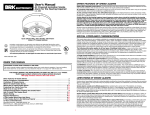
HOW THIS HEAT ALARM WORKS
Fixed Temperature and Rate-of-Rise.
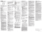
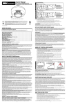
THE COVER OF YOUR HEAT ALARM
This Heat Alarm monitors the air and when heat reaches the sensor, it alarms.
The unit will alarm either when the temperature reaches a fixed 135º F (57º C) or
the microprocessor detects a 15º F (8.3º C) per minute rate of rise temperature
change. This allows the unit to sense a heat rise and alarm prior to reaching the
fixed temperature of 135º F (57º C), providing quicker response to a potential fire.
1. Power Light, Test/Silence Button
2
5
2. Remote Control “Eye”: Aim an infrared
remote control at the “Eye” on the Alarm
to test or silence the unit. (Works with
most infrared remote controls.)
4
Heat Alarms are intended for use as supplemental safety devices with Smoke
Alarms. Heat Alarms are designed for use in areas where Smoke Alarms
cannot be installed due to temperature and environmental conditions, as in
unheated garages and crawl spaces. A Heat Alarm can only give early warning of a developing fire if it is properly installed and maintained and located
where heat can reach it. The unit will not sense gas, smoke or flame. Heat
Alarms cannot prevent or extinguish fires.
3
3. Air Vents
4. (Behind the Cover) Alarm Horn: 85 dB
audible alarm for test, alarm, and unit
malfunction warning.
1
5. Heat Sensor
This Heat Alarm is approved for use in single-family residences. It is NOT
designed for marine or RV use.
HOW TO INSTALL THIS HEAT ALARM
This Heat Alarm is designed to be mounted on any standard wiring junction box to a 4-inch (10 cm) size, on either the ceiling or wall (if allowed by local codes).
Read “Recommended Locations For Heat Alarms” and “Locations to Avoid For Heat Alarms” before you begin installation.
Tools you will need: • Needle-nose pliers or utility knife • Standard Flathead screwdriver.
Make sure the Alarm is not receiving excessive noisy power. Examples of noisy power could be major appliances on the same circuit, power from a
generator or solar power, light dimmer on the same circuit or mounted near fluorescent lighting. Excessive noisy power may cause damage to your Alarm.
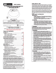
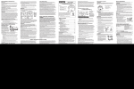
THE PARTS OF THIS HEAT ALARM
The Mounting Bracket:
To remove the mounting bracket from the Heat
Alarm base, hold the Heat Alarm base firmly and
twist the mounting bracket counterclockwise.
The mounting bracket installs onto the junction box.
It has a variety of screw slots to fit most boxes.
1
3
The Parts of This Unit
2
2
The Power Connector:
The power connector plugs into a power input block on
the Heat Alarm. It supplies the unit with AC power.
• The black wire is “hot.”
6
3
4
5
7
• The white wire is neutral.
8
• The orange wire is used for interconnect.
If you need to remove the power connector, disconnect
AC power at the electrical panel; insert a flat screwdriver
blade between the power connector and the security
tab inside the power input block. Gently pry back the
tab and pull the connector free.
9
2
1
Mounting Bracket
2
Mounting Slots and Screws
3
Locking Pins (break out of bracket)
4
Hot (Black) AC Wire
5
Neutral (White) AC Wire
6
Interconnect (Orange) Wire
7
Latch to Open Battery Compartment
8
Swing-Out Battery Compartment
9
Quick-Connect Power Connector
FOLLOW THESE INSTALLATION STEPS
The basic installation of this Heat Alarm is the similar whether you want to
install one Heat Alarm, or interconnect more than one Heat Alarm. If you
are interconnecting more than one Heat Alarm, you MUST read “Special
Requirements for Interconnected Heat Alarms” below before you begin
installation.
7. If the green power indicator light does not light, TURN OFF POWER TO
THE JUNCTION BOX and recheck all connections. If all connections are
correct and the power indicator still does not light when you restore the
power, the unit should be replaced immediately.
8. Test each Heat Alarm. Press the Test/Silence button until you hear a brief
acknowledge (or feedback) chirp. The alarm will sound: 3 beeps, pause,
3 beeps, pause.
When testing a series of interconnected units you must test each
unit individually. Make sure all units alarm when each one is tested.
ELECTRICAL SHOCK HAZARD. Turn off power to the area where you
will install this unit at the circuit breaker or fuse box before beginning
installation. Failure to turn off the power before installation may result
in serious electrical shock, injury or death.
1. Remove the mounting bracket from the base. Position the screw slots
on the mounting bracket over the screws in the junction box. Tighten
the screws.
If any unit in the series does not alarm, TURN OFF POWER and recheck
connections. If it does not alarm during testing when you restore power,
replace it immediately.
2. Using wire nuts, connect the power connector to the household wiring.
SPECIAL REQUIREMENTS FOR INTERCONNECTED HEAT ALARMS
Improper wiring of the power connector or the wiring leading to the
power connector will cause damage to the Alarm and may lead to a
non-functioning Alarm.
• Failure to meet any of these requirements could damage the units
and cause them to malfunction, removing your protection.
Interconnected units can provide earlier warning of fire than stand-alone
units, especially if a fire starts in a remote area of the dwelling. If any unit
in the series senses heat, all units will alarm.
STAND-ALONE ALARM ONLY:
•
•
Connect the white wire on the power connector to the neutral wire in
the junction box.
Connect the black wire on the power connector to the hot wire in the
junction box.
Tuck the orange wire inside the junction box. It is used for
interconnect only.
Strip off about 1/2” (12 mm) of the plastic coating on the orange
wire on the power connector.
Interconnect units within a single family residence only. Otherwise all households will experience unwanted alarms when you test any unit in the series.
Interconnected units will only work if they are wired to compatible units and
all requirements are met. This unit is designed to be compatible with:
First Alert® Smoke Alarm Models SA4120, SA4121B, SA4919B, SA100B
and BRK Electronics® Smoke Alarm Models 100S, 2002RAC, 4120, 4120B,
4120SB, 4919, 5919, 5919TH; BRK Electronics® Smoke/CO Alarm Model
SC6120B.
•
Interconnected units must meet ALL of the following requirements:
•
INTERCONNECTED UNITS ONLY:
•
•
•
Connect the white wire on the power connector to the neutral wire in
the junction box.
Connect the black wire on the power connector to the hot wire in the
junction box.
Connect the orange wire on the power connector to the interconnect
wire in the junction box. Repeat for each unit you are interconnecting.
Never connect the hot or neutral wires in the junction box to the orange
interconnect wire. Damage may result.
Never cross-connect hot and neutral wires between interconnected
Alarms. Damage will result.
• A maximum of 18 compatible Smoke, Heat or CO Alarms may be
interconnected. To comply with NFPA limits, no more than 12 of the
18 alarms may be Smoke Alarms.
• The same fuse or circuit breaker must power all interconnected units.
• All wiring must conform to all local electrical codes and NFPA 70 (NEC).
Refer to NFPA, Chapter 2 and/or your local building code for further
connection requirements.
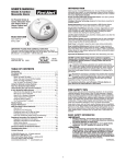
3. Plug the power connector into the back of the Heat Alarm.
A
4. Position the base of the Alarm over the mounting bracket and turn. The
Alarm can be positioned over the bracket every 60°. Turn the Alarm
clockwise (right) until the unit is in place.
5. Check all connections.
5
4
3
2
1
STAND-ALONE ALARM ONLY:
•
If you are only installing one Heat Alarm, restore power to the
junction box.
6
7 B
8
}
}
A. Unswitched 120VAC
60 Hz source
5
4
3
1
B. To additional units; Maximum = 18 total
(Maximum 12 Smoke Alarms)
INTERCONNECTED UNITS ONLY:
•
1. Heat Alarm
2. Ceiling or Wall
3. Power Connector
If you are interconnecting multiple Heat Alarms, repeat steps 1-5
for each Heat Alarm in the series. When you are finished, restore
power to the junction box.
ELECTRICAL SHOCK HAZARD. Do not restore power until all Heat
Alarms are completely installed. Restoring power before installation is
complete may result in serious electrical shock, injury or death.
6. Make sure the Heat Alarm is receiving AC power. Under normal
operation, the green light (LED) will shine continuously.
3
4. Wire Nut
5. Junction Box
6. Neutral Wire (Wht)
7. Interconnect Wire
(Orange)
8. Hot Wire (Blk)
LOCKING FEATURES
The locking features are designed to discourage unauthorized removal of the battery or alarm. It is not necessary to activate the locks in single-family
households where unauthorized battery or alarm removal is not a concern.
These Heat Alarms have two separate locking features: one to lock the battery compartment, and the other to lock the Heat Alarm
to the mounting bracket. You can choose to use either feature independently, or use them both.
Tools you will need: • Needle-nose pliers or utility knife • Standard Flathead screwdriver.
Locking Pin
Both locking features use locking pins, which are molded into the mounting bracket. Using needle nose pliers or a utility knife, remove one or
both pins from the mounting bracket, depending on how many locking features you want to use.
To permanently remove either lock insert a flathead screwdriver between the locking pin and the lock, and pry the pin out of the lock.
TO UNLOCK THE BATTERY COMPARTMENT
TO LOCK THE BATTERY COMPARTMENT
Do not lock the battery compartment until you have activated the
battery and tested the battery back-up.
Once the Heat Alarm is installed, you must disconnect it from the AC power
before unlocking the battery compartment.
1. Activate the battery back-up by removing the
“Pull to Activate Battery Back-Up” tab.
ELECTRICAL SHOCK HAZARD. Turn off the power to the area where the
Heat Alarm is installed before removing it from the mounting bracket.
Failure to turn off the power first may result in serious electrical shock,
injury or death.
DO NOT remove the battery activation until AC
power is turned on to conserve battery power.
2. Press the Test/Silence button until you hear a brief acknowledge (or
feedback) chirp. The alarm will sound: 3 beeps, pause, 3 beeps, pause.
Turn off the AC power at the circuit breaker or fuse box.
1. Remove the Heat Alarm from the mounting bracket. If the unit is locked
to the bracket, see the section “To Unlock the Mounting Bracket.”
2. Disconnect the power connector by gently
prying it away from the back of the Heat Alarm.
3. Insert a flathead screwdriver under the head of
the locking pin, and gently pry it out of the battery
compartment lock. (If you plan to relock the
battery compartment, save the locking pin.)
4. To relock the battery compartment, close the
battery door and reinsert locking pin in lock.
5. Reconnect the power connector to the back of the Alarm, reattach the
Heat Alarm to the mounting bracket, and restore the power.
If the unit does not alarm during testing, DO
NOT lock the battery compartment! Install a
new battery and test again. If the Heat Alarm
still does not alarm, replace it immediately.
3. Using needle-nose pliers or a utility knife,
detach one locking pin from the mounting
bracket.
4. Push the locking pin through
the black dot on the label on
the back of the Heat Alarm.
When replacing the battery, always test the Heat Alarm before relocking the
battery compartment.
TO LOCK THE MOUNTING BRACKET
TO UNLOCK THE MOUNTING BRACKET
ELECTRICAL SHOCK HAZARD. Turn off the power to the area where the
Heat Alarm is installed before removing it from the mounting bracket.
Failure to turn off the power first may result in serious electrical shock,
injury or death.
Always discharge the branch circuit before servicing an AC or AC/DC
Heat Alarm. First, turn off the AC power at the circuit breaker or fuse box.
Next, remove the battery from Alarms with battery back-up. Finally, press
the test button to discharge the branch circuit.
1. Using needle-nose pliers, detach one locking pin from mounting bracket.
1. Insert a flathead screwdriver between the mounting bracket pin and the
mounting bracket.
2. Insert the locking pin into the lock located on the pivoting hinge of the
battery door.
3. When you attach the Alarm to the mounting bracket, the locking pin’s
head will fit into a notch on the bracket.
2. Pry the Heat Alarm away from the bracket by turning both the screwdriver and the Heat Alarm counterclockwise (left) at the same time.
4
WEEKLY TESTING
•
NEVER use an open flame of any kind to test this unit. You might
accidentally damage or set fire to the unit or to your home. The builtin test switch accurately tests the unit’s operation as required by
Underwriters Laboratories, Inc. (UL).
•
If the Alarm ever fails to test properly, replace it immediately.
Products under warranty may be returned to the manufacturer for
replacement. See “Limited Warranty” at the end of this manual.
•
IF YOU SUSPECT A PROBLEM
Heat Alarms may not operate properly because of dead, missing or weak
batteries, a build-up of dirt, dust or grease on the Heat Alarm cover, or
installation in an improper location. Clean the Heat Alarm as described in
“Regular Maintenance,” and install a fresh battery, then test the Heat Alarm
again. If it fails to test properly when you use the test button, or if the problem
persists, replace the Heat Alarm immediately.
DO NOT stand close to the Alarm when the horn is sounding.
Exposure at close range may be harmful to your hearing. When
testing, step away when horn starts sounding.
It is important to test this unit every week to make sure it is working
properly. Press and hold the test button until the alarm sends a test command
acknowledge “chirp” just before it sounds continuously (the unit will continue
to alarm for a few seconds after you release the button). If it does not alarm,
make sure it is receiving power and has a fresh battery, and test it again.
If it still does not alarm, it should be replaced immediately.
If the Alarm does not respond to your remote control:
• You may be standing too far away.
• Your remote may not be compatible.
• You did not hold the button on your remote for at least 2 seconds.
REGULAR MAINTENANCE
This unit has been designed to be as maintenance-free as possible, but there
are a few simple things you must do to keep it working properly.
Use only the replacement batteries listed below. The unit may not
operate properly with other batteries. Never use rechargeable batteries
since they may not provide a constant charge.
•
If the Heat Alarm becomes contaminated by excessive dirt, dust and/or
grime, and cannot be cleaned to avoid unwanted alarms, replace the
unit immediately.
•
Relocate the unit if it sounds frequent unwanted alarms. See “Locations
to Avoid for Heat Alarms” for details.
•
When the battery becomes weak, the Heat Alarm unit will “chirp” about
once a minute (the low battery warning). You should replace the battery
immediately to continue your protection.
If the alarm sounds when no smoke is visible, try cleaning or
relocating the Heat Alarm. The cover may be dirty.
•
If the alarm does not sound during testing, make sure it is receiving
AC power from the household current.
UNDERSTANDING THE INDICATOR LIGHTS
AND ALARM HORN PATTERNS
To Test (or Silence) the Alarm:
1. Make sure you have a clear path between you and the alarm, free of any
obstructions.
2. Point the remote at the front of the Alarm.
3. Press the VOLUME or CHANNEL button for at least 2 seconds. You will
hear a brief acknowledge “chirp” when the Alarm receives the test (or
silence) command.
Clean the Heat Alarm at least once a month; gently vacuum the
outside of the Heat Alarm using your household vacuum’s soft brush
attachment. Test the Heat Alarm. Never use water, cleaners or solvents
since they may damage the unit.
•
If the Heat Alarm is still not operating properly, and it is still under warranty,
please see “How to Obtain Warranty Service” in the Limited Warranty.
Using the VOLUME or CHANNEL buttons on most remote controls, you can
test or silence this Alarm from up to 12 feet (3.7 meters) away.
•
If you experience frequent non-emergency alarms try relocating the
Heat Alarm.
Do not try fixing the alarm yourself – this will void your warranty!
USING THE REMOTE CONTROL WEEKLY
TEST/SILENCE FEATURE
Test it at least once a week.
If you hear a “chirp” once a minute, replace the battery.
•
Always discharge the branch circuit before servicing an AC or AC/DC
Heat Alarm. First, turn off the AC power at the circuit breaker or fuse
box. Next, remove the battery from Heat Alarms with battery back-up.
Finally, press the test button to discharge the branch circuit.
When testing one unit, all interconnected alarms will sound. If they don’t,
check the connection with power to the units turned off, restore power and
try again. Test all units in a series, not just one. Using the test button is the
ONLY correct way to test the Heat Alarm.
•
•
Choosing a replacement battery:
Your Heat Alarm’s battery back-up requires one standard 9V battery. The
following batteries are acceptable as replacements. This list supplements
the list on the Heat Alarm battery door: Eveready #522 (Energizer); Duracell
#MN1604, MX1604 (Ultra). You may also use a Lithium battery like the Ultralife
U9VL-J for longer service life between battery changes. These batteries are
available at many local retail stores.
Condition
LED
Horn
AC POWER ON
(Normal operation)
LED shines GREEN
continuously
Silent; no audible
alarm
DC POWER
(Battery back-up
active)
LED flashes GREEN
once per minute while
battery powers unit
One horn “chirp” to
signal loss of AC
power
RESUME AC POWER
GREEN LED turns ON
Horn “chirps” one time
to signal resumption of
AC power
DURING TESTING
(Under AC or DC
power)
LED flashes RED, the
same pattern as the
horn
Audible alarm:
3 beeps, pause,
repeating horn pattern
ALARM CONDITION*
(Initiating Unit)
LED flashes RED, the
same pattern as the
horn
Audible alarm:
3 beeps, pause,
repeating horn pattern
LATCHING ALARM
ACTIVE** (Under AC
or DC Power)
LED flashes RED once
every 5 seconds
Silent; no audible
alarm
ALARM SILENCE
LED flashes RED once
every 5 seconds
No signal
LOW BATTERY
GREEN LED flashes
once every minute
Horn “chirps” once
per minute, in sync
with LED. NOTE: If the
battery is VERY LOW,
the horn may either
chirp once per
second, or sound
continuously
MALFUNCTION
(Unit MUST be
replaced)
LED flashes RED
rapidly three times, in
sync with three horn
“chirps”, once every
minute
Horn “chirps” three
times, in sync with
three LED flashes
*When any Heat Alarm in an interconnected series triggers an alarm, its red LED
will flash rapidly. The red LEDs will not flash on any remaining alarms in the
series. This feature helps responders identify which unit(s) triggered the alarm.
**The Latching Alarm indicator is activated after an Alarm is exposed to alarm
levels of heat. After heat levels drop below alarm levels, the LED begins to flash
RED once every 5 seconds. See “The Latching Alarm Indicator” for details.
Actual service life depends on the Heat Alarm and the environment in which it
is installed. Constant exposures to high or low temperatures or high humidity
may reduce battery life. All the batteries specified above are acceptable
replacement batteries for this unit. Use of a different battery may have a
detrimental effect on Alarm operation. Regardless of the manufacturer’s
suggested battery life, you MUST replace the battery immediately once the
unit starts “chirping” (the “low battery warning”).
5
IF THIS HEAT ALARM SOUNDS
“LATCHING ALARM” INDICATOR
RESPONDING TO AN ALARM
During an alarm, you will hear a loud, repeating horn pattern:
3 beeps, pause, 3 beeps, pause.
KEY:
• If the unit alarms and you are not testing the unit, it is warning you
of a potentially dangerous situation that requires your immediate
attention. NEVER ignore any alarm. Ignoring the alarm may result
in injury or death.
• Never disconnect the AC power or remove the battery back-up to
quiet an unwanted alarm. Disconnecting the power disables the
alarm so it cannot sense heat. This will remove your protection.
• If the unit alarms and you are not absolutely certain of the source
of the heat, get everyone out of the house immediately.
BEDROOM
BEDROOM
KITCHEN
LIVING ROOM
BEDROOM
LATCHING ALARM:
Unit was exposed
to alarm levels of Smoke
or Heat
GARAGE
HALL
LATCHING NOT ACTIVATED:
Unit was not exposed
to alarm levels of Smoke
or Heat
BASEMENT
The Latching Alarm Indicator is activated after an Alarm is exposed to
alarm levels of heat. After heat levels drop below alarm levels, the red LED
will begin to flash once every 5 seconds. It will continue to flash or “latch”
until you clear it using the Test/Silence button. Press and hold the
Test/Silence button until the horn sounds.
This feature helps emergency responders, investigators, or service technicians
identify which unit(s) in your home were exposed to alarm levels of heat. This
can help investigators pinpoint the initiating alarm.
• ELECTRICAL SHOCK HAZARD: Attempting to disconnect the power
connector from the unit when the power is on may result in electrical
shock, serious injury or death.
When an interconnected system of units is in alarm, the Red LED on the
unit(s) that initiated the alarm will flash in sync with the horn. The LED will not
flash on any remaining units.
WHAT TO DO IN CASE OF FIRE
•
•
•
•
•
•
•
•
RECOMMENDED LOCATIONS FOR HEAT ALARMS
Don’t panic; stay calm. Follow your family escape plan.
Get out of the house as quickly as possible. Don’t stop to get dressed or
collect anything.
Feel doors with the back of your hand before opening them.
If a door is cool, open it slowly. Don’t open a hot door. Keep doors
and windows closed, unless you must escape through them.
Cover your nose and mouth with a cloth (preferably damp).
Take short, shallow breaths.
Meet at your planned meeting place outside your home, and do a head
count to make sure everybody got out safely.
Call the Fire Department as soon as possible from outside.
Give your address, then your name.
Never go back inside a burning building for any reason.
Contact your Fire Department for ideas on making your home safer.
In Single-Family Residences.
For minimum coverage, BRK Brands, Inc. recommends you install Heat
Alarms in any area not suitable for smoke alarms such as garages, kitchens,
utility/laundry rooms, furnace rooms and crawl spaces. Install where temperatures normally remain between –10º F and 100º F (–23º C and 38º C).
For National Fire Protection Association (NFPA) information, see “Agency
Placement Recommendations for Heat Alarms and Smoke Alarms.”
RECOMMENDED PLACEMENT
USING THE SILENCE FEATURES
INTERCONNECTED HEAT ALARMS IN
GARAGES, KITCHENS, UTILITY/LAUNDRY
ROOMS, FURNACE ROOMS AND CRAWL
SPACES AND ONLY AS A SUPPLEMENT TO
SMOKE ALARMS.
BEDROOM
If you are absolutely certain the alarm is caused by a non-emergency,
non-fire situation, you may use the Silence Feature to silence the Alarm.
The Silence Feature on this unit can temporarily quiet an unwanted alarm for
up to 15 minutes.
LIVING ROOM
BEDROOM
HALL
KITCHEN
BEDROOM
FOR MAXIMUM PROTECTION USE
INTERCONNECTED SMOKE ALARMS WITH
BATTERY BACK-UP AS SHOWN.
GARAGE
BASEMENT
The Silence Feature is for your convenience only and will not correct a
problem.
Heat Alarms Recommended in New Home Construction
The Silence Feature is intended to temporarily silence the Alarm horn. It will
not extinguish a fire.
25 ft.
(7.8 m)
To temporarily silence the alarm:
1. Option 1: Press the Test/Silence button on the cover of the Heat Alarm
that initiated the alarm.*
2. Option 2: Point a universal IR remote control at the Heat Alarm that initiated
the alarm* and press the channel or volume button until the alarm is silent.
(See “Using the Remote Control Weekly Test/Silence Feature” for details).
An acknowledge tone will be issued by the Alarm to let you know that the
silence command has been received.
12.5 ft.
(3.8 m)
50 ft.
(15 m)
25 ft.
(7.8 m)
25 ft.
(7.8 m)
25 ft.
(7.8 m)
12.5 ft.
(3.8 m)
Heat Alarms should be mounted on the bottom
of the joists and not up in the joist channels.
*To silence Heat Alarms in an interconnected series:
To silence multiple Alarms in an interconnected series, you must press the
Test/Silence button on the unit(s) that triggered the alarm. Pressing the Test/
Silence button on a unit that did not trigger the alarm will only silence that
Alarm.
NOTE: The red light under the Silence button on the initiating alarm will flash
in sync with the horn. The red light will be off on all other Heat Alarms.
• The recommended location for a Heat Alarm is at the center of the ceiling. At this location, the Heat Alarm is closest to all areas of the room.
If any unit will not silence and no heat is present install a new battery and
re-test it. If it still will not silence, the unit should be replaced immediately.
• If it is not practical to install the Heat Alarm on the ceiling, the next
logical location is on a sidewall. A Heat Alarm mounted on a sidewall
should have the top of the unit between 4 and 12 inches (102 mm and
305 mm) from the ceiling.
• If it is not practical to install the Heat Alarm in the center of the room,
use an off-center location not less than 4 inches (102 mm) from the
sidewall.
LOW BATTERY SILENCE FEATURE
If AC power is on, briefly press the Test/Silence button or use a Remote
Control to silence the low battery “chirp” for up to 8 hours. A brief “chirp” will
let you know that the Alarm has accepted the Low Battery Silence command.
The Alarm will continue to operate as long as AC power is supplied. However,
replace the battery as soon as possible, to maintain protection in event of a
power outage.
• The smooth ceiling distance between Heat Alarms shall not exceed
spacings as determined by UL fire tests. This Heat Alarm has a 50 foot
(15 meter) spacing.
• Reduced spacing may be required due to factors such as exposed
joists, drafts, ceiling heights greater than 10 feet (3 meters), and other
structural characteristics that may affect Heat Alarm operation. Walls,
partitions, doorways, and joists interrupt the normal flow of heat
creating new areas to be protected.
Continued...
6
LOCATIONS TO AVOID FOR HEAT ALARMS
RECOMMENDED PLACEMENT, Continued
NFPA Standard 72 Appendix A-2-5.2.2.2 part c-d
(c) The Spacing of Detectors: Where a room is too large for protection
by a single detector, several detectors should be used. It is important
that they be properly located so all parts of the room are covered.
(d) Where the Distance Between Detectors Should Be Further Reduced:
The distance between detectors is based on data obtained from the
spread of heat across a smooth ceiling. Where the ceiling is not smooth,
the placement of the detector should be tailored to the situation.
This unit works best when it’s clean and nothing interferes with the sensor. If
exposed to dirt, grease, extreme temperatures not caused by fire (especially in
attics where daily temperatures can exceed the 135º F (57º C) alarm level or
high humidity, it may sound “unwanted” alarms. If Heat Alarms are installed
where heat can’t reach them–like in “dead air spaces” or near fans–they may
not be able to provide an early enough warning in case of fire.
For best performance, do not install the Heat Alarm:
In a location where it could be easily triggered when
using your remote to operate your TV, VCR, or other
remote controlled appliances.
For instance, with open wood joists, heat travels freely down the joist
channels so that the maximum distance between detectors [50 ft (15 m)]
may be permitted to be used. However, heat has trouble spreading
across the joists, so the distance in this direction should be 1/2 the
distance allowed between detectors, as shown in the illustration above
(“Heat Alarms Recommended in New Home Construction”) and the
distance to the wall is reduced to 12-1/2 ft. (3.8 m). Since 1/2 x 50 ft.
(15 m) is 25 ft. (7.6 m), the distance between detectors across open
wood joists should not exceed 25 ft. (7.6 m), as shown in “Heat Alarms
Recommended in New Home Construction,” and the distance to the wall
is reduced [1/2 x 25 ft. (7.6 m)] to 12.5 ft. (3.8 m). Paragraph 2-5.2.2.4
requires that detectors be mounted on the bottom of the joists and not
up in joist channels.
•
•
•
•
•
Walls, partitions, doorways, ceiling beams, and open joists interrupt the
normal flow of heat, thus creating new areas to be protected.
Where temperatures are regularly below –20º F (–29º C) or above 115º F
(46º C), including unheated buildings, outdoor rooms, or porches.
Do not install a Heat Alarm directly over the stove or range. Clean a
laundry room unit frequently to keep it free of dirt or lint.
Near fresh air vents, ceiling fans, or in very drafty areas. Drafts can blow
heat away from the unit, preventing it from reaching the sensing chamber.
In “dead air” spaces. Install units according to “Avoiding Dead Air Spaces”.
Less than 12 inches (305 mm) away from fluorescent lights. Electrical
“noise” can interfere with the sensor.
AVOIDING DEAD AIR SPACES
“Dead air” spaces may prevent heat from reaching the Heat Alarm. To avoid
dead air spaces, follow installation instructions in the “Recommended
Locations for Heat Alarms” (refer to NFPA72 for details).
AGENCY PLACEMENT RECOMMENDATIONS FOR HEAT
AND SMOKE ALARMS
NFPA Appendix A-2-5.2.2: While Chapter 2 does not require heat detectors as
part of the basic protection scheme, it is recommended that the householder
consider the use of additional heat detectors...The additional areas lending
themselves to protection with heat detectors are: kitchen, dining room, attic
(finished or unfinished), furnace room, utility room, basement and integral or
attached garages. For bedrooms, the installation of a smoke detector is
preferable to the installation of a heat detector.
For wall mounting (if allowed by building codes), the top edge of Heat Alarms
should be placed between 4 inches (102 mm) and 12 inches (305 mm) from
the wall/ceiling line, below typical “dead air” spaces.
The following recommendations reference location and usage of Smoke
Alarms. Heat Alarms are intended as supplemental safety devices.
Do not rely solely on Heat Alarms to alert you to fire.
The following recommendations reference location and usage of Smoke
Alarms. Heat Alarms are only intended as supplemental safety devices.
Do not rely solely on Heat Alarms to alert you to fire.
NFPA 72 (National Fire Code)
Smoke Alarms shall be installed in each separate sleeping room, outside each
sleeping area in the immediate vicinity of the bedrooms and on each additional
story of the family living unit, including basements and excluding crawl spaces
and unfinished attics.
In new construction, Alarms shall be so arranged that operation of any one
Alarm shall cause the operation of all Alarms within the dwelling.
Smoke Detection-Are More Smoke Alarms Desirable? The required number
of Smoke Alarms might not provide reliable early warning protection for those
areas separated by a door from the areas protected by the required Smoke
Alarms. For this reason, it is recommended that the householder consider the
use of additional Smoke Alarms for those areas for increased protection.
The additional areas include the basement, bedrooms, dining room, furnace
room, utility room, and hallways not protected by the required Smoke Alarms.
The installation of Smoke Alarms in kitchens, attics (finished or unfinished), or
garages is not normally recommended, as these locations occasionally
experience conditions that can result in improper operation.
This unit alone is not a suitable substitute for complete fire detection
systems in places housing many people—like apartment buildings,
condominiums, hotels, motels, dormitories, hospitals, long-term health
care facilities, nursing homes, day care facilities, or group homes of any
kind—even if they were once single-family homes. It is not a suitable
substitute for complete fire detection systems in warehouses, industrial
facilities, commercial buildings, and special-purpose non-residential
buildings which require special fire detection and alarm systems.
Depending on the building codes in your area, this unit may be used to
provide additional protection in these facilities.
SPECIAL COMPLIANCE CONSIDERATIONS
For your reference: The following is information on Smoke Alarm usage
in various residences and institutions.
The following information applies to all five types of buildings listed below:
In new construction, most building codes require the use of AC or AC/DC
powered Smoke Alarms only. AC, AC/DC, or DC powered Smoke Alarms can
be used in existing construction as specified by local building codes. Refer to
NFPA 72 (National Fire Alarm Code) and NFPA 101 (Life Safety Code), local
building codes, or consult your Fire Department for detailed fire protection
requirements in buildings not defined as “households.”
California State Fire Marshal (CSFM)
Early warning detection is best achieved by the installation of fire detection
equipment in all rooms and areas of the household as follows: A Smoke Alarm
installed in each separate sleeping area (in the vicinity, but outside bedrooms),
and Heat or Smoke Alarms in the living rooms, dining rooms, bedrooms,
kitchens, hallways, finished attics, furnace rooms, closets, utility and storage
rooms, basements, and attached garages.
Additional local building and regulatory codes may apply in your area.
Always check compliance requirements before beginning any installation.
1. Single-Family Residence:
Single family home, townhouse. It is recommended Smoke Alarms be
installed on every level of the home, in every bedroom, and in each bedroom
hallway.
2. Multi-Family or Mixed Occupant Residence:
Apartment building, condominium. This Smoke Alarm is suitable for use in
individual apartments or condos, provided a primary fire detection system
already exists to meet fire detection requirements in common areas like
lobbies, hallways, or porches. Using this Smoke Alarm in common areas
may not provide sufficient warning to all residents or meet local fire protection
ordinances/regulations.
Specific requirements for Heat or Smoke Alarm installation vary from state to
state and from region to region. Check with your local Fire Department for
current requirements in your area. If you install AC or AC/DC units, it is recommended they be interconnected for added protection. Interconnect Smoke and
Heat Alarms for added protection.
3. Institutions:
Hospitals, day care facilities, long-term health care facilities. This Smoke
Alarm is suitable for use in individual patient sleeping/resident rooms,
provided a primary fire detection system already exists to meet fire detection
requirements in common areas like lobbies, hallways, or porches. Using this
Smoke Alarm in common areas may not provide sufficient warning to all
residents or meet local fire protection ordinances/regulations.
4. Hotels and Motels:
Also boarding houses and dormitories. This Smoke Alarm is suitable for use
inside individual sleeping/resident rooms, provided a primary fire detection
system already exists to meet fire detection requirements in common areas
like lobbies, hallways, or porches. Using this Smoke Alarm in common areas
may not provide sufficient warning to all residents or meet local fire protection
ordinances/regulations.
5. Warehouses/Commercial Buildings:
DO NOT use this Alarm in warehouses, industrial or commercial buildings,
special-purpose non-residential buildings, RVs, boats, or airplanes. This Alarm
is specifically designed for residential use, and may not provide adequate
protection in non-residential applications.
7
LIMITATIONS OF HEAT ALARMS
This Heat Alarm is not a Smoke Alarm. This unit is not suitable protection
when used alone. Do not use this unit as the only means of fire detection
in a home. This unit is intended for use as a supplement to Smoke
Alarms.
Heat Alarms may not sense heat from a fire on another level of the home.
Example: a stand-alone unit on the second floor may not detect heat from a
fire in a crawl space until the fire spreads. This may not give you enough time
to escape safely. That is why recommended minimum protection is at least
one Smoke Alarm on every level of your home and Heat Alarms in any areas
not suitable for Smoke Alarms. Even with a unit on every floor, stand-alone
units may not provide as much protection as interconnected units, especially
if the fire starts in a remote area. Interconnected units may provide earlier
warning than stand-alone units since all units alarm when one senses heat
or smoke.
Heat Alarms are not life safety devices.
Heat Alarms are intended for use as supplements to Smoke Alarms.
Because this unit cannot detect smoke, carbon monoxide or other toxic gases,
do not rely solely on this Heat Alarm in a fire emergency. Slow developing fires
may produce smoke and toxic gasses without a significant increase in room
temperatures. For this reason, Heat Alarms are only to be installed as
supplementary protection with Smoke Alarms.
Heat Alarms may not be heard. The alarm horn loudness meets or exceeds
the current UL standard. However, if the device is installed outside the bedroom, it may not wake up a sound sleeper or one who has recently used
drugs or has been drinking alcoholic beverages. This is especially true if the
door is closed or only partly open. Even persons who are awake may not
hear the alarm horn if the sound is blocked by distance or closed doors.
Noise from traffic, stereo, radio, television, air conditioner, or other appliances
may also prevent alert persons from hearing the alarm horn. This alarm
device is not intended for people who are hearing impaired.
Heat Alarms cannot work without power. AC powered Heat Alarms and
Smoke Alarms cannot work if the AC power is cut off for any reason (open
fuse or circuit breaker, failure along a power line or at a power station,
electrical fire that burns the electrical wires, etc.).
AC units with battery (DC) back-up: will operate if electricity fails, provided
the batteries are fresh and correctly installed. AC and AC/DC units must be
installed by a qualified electrician.
Heat Alarms may not have time to alarm before the fire itself causes
damage, injury, or death, since heat from some fires may not reach the
unit immediately. Examples of this include persons smoking in bed,
children playing with matches, or fires caused by violent explosions
resulting from escaping gas.
Heat Alarms for Solar or Wind Energy users and battery backup power
systems: AC powered Heat Alarms should only be operated with true or pure
sine wave inverters. Operating this Heat Alarm with most battery-powered
UPS (uninterruptible power supply) products or square wave or “quasi sine
wave” inverters will damage the Alarm. If you are not sure about your inverter
or UPS type, please consult with the manufacturer to verify.
This Heat Alarm is not foolproof. Like any electronic device, Heat Alarms are
made of components that can wear out or fail at any time. You must test the
unit weekly to ensure your continued protection. Heat Alarms cannot prevent
or extinguish fires. They are not a substitute for property or life insurance.
Heat Alarms cannot sense fires if the heat does not reach them. Heat
from fires in chimneys or walls, on roofs, or on the other side of closed doors
may not reach the sensing chamber and set off the alarm. That is why one
unit should be installed on every floor, in the attic, basement and garage and
only as a supplement to Smoke Alarms.
Heat Alarms have a limited life. The unit should be replaced immediately if it
is not operating properly. In no case should it be used for more than 10 years.
LIMITED WARRANTY
BRK Brands, Inc., ("BRK") the maker of BRK® brand and First Alert® brand products warrants that for a period of ten years from the date of purchase, this product
will be free from defects in material and workmanship. BRK, at its option, will repair or replace this product or any component of the product found to be defective
during the warranty period. Replacement will be made with a new or remanufactured product or component. If the product is no longer available, replacement may
be made with a similar product of equal or greater value. This is your exclusive warranty.
This warranty is valid for the original retail purchaser from the date of initial retail purchase and is not transferable. Keep the original sales receipt. Proof of purchase
is required to obtain warranty performance. BRK dealers, service centers, or retail stores selling BRK products do not have the right to alter, modify or any way
change the terms and conditions of this warranty.
This warranty does not cover normal wear of parts or damage resulting from any of the following: negligent use or misuse of the product, use on improper voltage or
current, use contrary to the operating instructions, disassembly, repair or alteration by anyone other than BRK or an authorized service center. Further, the warranty
does not cover Acts of God, such as fire, flood, hurricanes and tornadoes or any batteries that are included with this unit.
BRK shall not be liable for any incidental or consequential damages caused by the breach of any express or implied warranty. Except to the extent prohibited by
applicable law, any implied warranty of merchantability or fitness for a particular purpose is limited in duration to the duration of the above warranty. Some states,
provinces or jurisdictions do not allow the exclusion or limitation of incidental or consequential damages or limitations on how long an implied warranty lasts, so the
above limitations or exclusion may not apply to you. This warranty gives you specific legal rights, and you may also have other rights that vary from state to state or
province to province.
How to Obtain Warranty Service
Service: If service is required, do not return the product to your retailer. In order to obtain warranty service, contact the Consumer Affairs Division at 1-800-323-9005,
7:30 AM - 5:00 PM Central Standard Time, Monday through Friday. To assist us in serving you, please have the model number and date of purchase available when
calling. For Warranty Service return to: BRK Brands, Inc., 25 Spur Drive, El Paso, TX 79906
Battery: BRK Brands, Inc. make no warranty, express or implied, written or oral, including that of merchantability or fitness for any particular purpose with
respect to battery.
Please record Date and Where Purchased:
________________________________________________________________
BRK® is a registered trademark of BRK Brands, Inc.
First Alert® is a registered trademark of the First Alert Trust.
Printed in Mexico M08-0026-003 Q 08/08
8