1
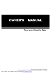
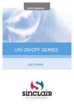
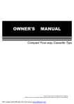
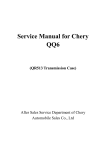
2
1
3
INDOOR UNIT
4
6
7
5
AU
TO
CO
OL
DR
Y
HE
AT
FAN
TEM
SE P
T
CLOC
SET
FAN
MO
M
8
K
HOU
R
SPEE
D
DE
10
FAN
SPE
ED
SW
SW
RESE
11
9
ING
AIR
ING
T LOCK
DIRE
CTIO
N
CLO
OK
CK
C/H
TIM
ECO
E ON
TIM
E OFF
11
OUTDOOR UNIT
12
10
12
OR
11
10
11
12
11
11
11
Fig.1
1
2
3
Drain pump(drain water from indoor unit)
4
5
Air outlet
Air filter(inside air-in grill)
6
Air inlet
Air flow louver(at air outlet)
Drain pipe
7
8
9
10
11
12
Air-in grill
Display panel
Remote controller
Refrigerant pipe
Air inlet
Air outlet
NOTE
All the pictures in this manual are for explanation purpose only. They may be slightly different from the air
conditioner you purchased(depend on model).The actual shape shall prevail.
CONTENTS
PAGE
1.IMPORTANT SAFETY INFORMATION........................................................1
2.PARTS NAMES......................................................................................2
3.AIR CONDITIONER OPENRATIONS AND PERFORMANCE........................2
4.HINTS FOR ECONOMICAL OPERATION...................................................3
5.ADJUSTING AIR FLOW DIRECTION........................................................3
It is not good for your health to expose your body to the
air flow for a long time.
Do not insert fingers, rods or other objects into the air
inlet or outlet.
When the fan is rotating at high speed, it will cause injury.
Never use a flammable spray such as hair spray, lacquer
or paint near the unit.
It may cause a fire.
6.MAINTENANCE.....................................................................................4
7.FOLLOWING SYMPTOMS ARE NOT AIR CONDITIONER TROUBLES........5
8.TROUBLESHOOTING.............................................................................5
Never touch the air outlet or the horizontal blades while
the swing flap is in operation.
Fingers may become caught or the unit may break down.
Never put any objects into the air inlet or outlet.
Objects touching the fan at high speed can be dangerous.
Never inspect or service the unit by yourself.
Ask a qualified service person to perform this work.
Do not dispose this product as unsorted municipal
waste. Collection of such waste separately for special
treatment is necessary.
1.
IMPORTANT SAFETY INFORMATION
To prevent injury to the user or other people and property
damage, the following instructions must be followed. Incorrect
operation due to ignoring of instructions may cause harm or
damage.
The safety precautions listed are divided into two categories. In either
case, important safety information is listed which must be read
carefully.
WARNING
Failure to observe a warning may result in death. The
appliance shall be installed in accordance with national
wiring regulations.
CAUTION
Failure to observe a caution may result in injury or damage
to the equipment.
WARNING
Ask your dealer for installation of the air conditioner.
Incomplete installation performed by yourself may result in a
water leakage, electric shock, and fire.
Ask your dealer for improvement, repair, and
maintenance.
Incomplete improvement, repair, and maintenance may result
in a water leakage, electric shock, and fire.
In order to avoid electric shock, fire or injury, or if you
detect any abnormality such as smell of fire, turn off the
power supply and call your dealer for instructions.
Never let the indoor unit or the remote controller get wet.
It may cause an electric shock or a fire.
Never press the button of the remote controller with a
hard, pointed object.
The remote controller may be damaged.
Never replace a fuse with that of wrong rated current or
other wires when a fuse blows out.
Use of wire or copper wire may cause the unit to break down
or cause a fire.
owner’s manual
1
Do not dispose of electrical appliances as unsorted
municipal waste, use separate collection facilities.
Contact you local government for information regarding the
connection systems available.
If electrical appliances are disposed of in landfills or
dumps, hazardous substances can leak into the
groundeater and get into the food chain, damaging your
health and well-being.
To prevent refrigerant leak, contact your dealer.
When the system is installed and runs in a small room, it is
required to keep the concentration of the refrigerant, if by any
chance coming out, below the limit. Otherwise, oxygen in the
room may be affected, resulting in a serious accident.
The refrigerant in the air conditioner is safe and normally
does not leak.
If the refrigerant leaks in the room, contact with a fire of a
burner, a heater or a cooker may result in a harmful gas.
Turn off any combustible heating devices, ventilate the
room, and contact the dealer where you purchased the
unit.
Do not use the air conditioner until a service person confirms
that the portion where the refrigerant leaks is repaired.
CAUTION
Do not use the air conditioner for other purposes.
In order to avoid any quality deterioration, do not use the unit
for cooling precision instruments, food, plants, animals or
works of art.
Before cleaning, be sure to stop the operation, turn the
breaker off or pull out the supply cord.
Otherwise, an electric shock and injury may result.
In order to avoid electric shock or fire, make sure that an
earth leak detector is installed.
Be sure the air conditioner is grounded.
In order to avoid electric shock, make sure that the unit is
grounded and that the earth wire is not connected to gas or
water pipe, lightning conductor or telephone earth wire.
In order to avoid injury, do not remove the fan guard of
the outdoor unit.
If the supply cord is damaged, it must be replaced by the
manufacturer, its service agent or similarly qualified
persons in order to avoid a hazard.
Do not operate the air conditioner with a wet hand.
An electric shock may happen.
Do not touch the heat exchanger fins.
These fins are sharp and could result in cutting injuries.
Do not place items which might be damaged by moisture
under the indoor unit.
Condensation may form if the humidity is above 80%, the
drain outlet is blocked or the filter is polluted.
After a long use, check the unit stand and fitting for
damage.
If damaged, the unit may fall and result in injury.
Do not operate your air conditioner in a wet room such
as a bathroom or laundry room.
2.
PARTS NAMES
The air conditioner consists of the indoor unit, the outdoor unit,
the connecting pipe and the remote controller. (See Fig.2)
Function indicators on indoor unit display panel
Infrared signal receiver
Temporary button
To avoid oxygen deficiency, ventilate the room
sufficiently if equipment with burner is used together
with the air conditioner.
Arrange the drain hose to ensure smooth drainage.
Incomplete drainage may cause wetting of the building,
furniture etc.
Operation lamp
PRE-DEF indicator(cooling and heating type)
or fan only indicator(cooling only type)
Never touch the internal parts of the controller.
Do not remove the front panel. Some parts inside are
dangerous to touch, and a machine trouble may happen.
Display panel Fig.2-1
Never expose little children, plants or animals directly to
the air flow.
Adverse influence to little children, animals and plants may
result.
Temporary button
Do not allow a child to mount on the outdoor unit or
avoid placing any object on it.
Falling or tumbling may result in injury.
Operation lamp
This appliance can be used by children aged from 8
years and above and persons with reduced physical,
sensory or mental capabilities or lack of experience
and knowledge if they have been given supervision
or instruction concerning use of the appliance in a safe
way and understand the hazards involved. Children shall
not play with the appliance. Cleaning and user
maintenance shall not be made by children without
supervision.
This appliance is not intended for use by persons
(including children) with reduced physical, sensory or
mental capabilities, or lack of experience and
knowledge, unless they have been given supervision
or instruction concerning use of the appliance by a
person responsible for their safety.
Children should be supervised to ensure that they do not
play with the appliance.
Timer indicator
Alarm indicator
PRE-DEF indicator(cooling and heating type)
or fan only indicator(cooling only type)
Display panel Fig.2-2
This function is used to operate the unit temporarily in case you
misplace the remote controller or its batteries are exhausted.
Two modes including AUTO and FORCED COOL can be
selected through the TEMPORARY BUTTON on the air-in grill
control box of the indoor unit. Once you push this button, the air
conditioner will run in such order: AUTO, FORCED COOL,
OFF, and back to AUTO.
Do not place appliances which produce open fire in
places exposed to the air flow from the unit or under the
indoor unit.
It may cause incomplete combustion or deformation of the
unit due to the heat.
The appliance is not intended for use by young children
or infirm persons without supervision.
Infrared signal receiver
FUNC
Do not operate the air conditioner when using a room
fumigation - type insecticide.
Failure to observe could cause the chemicals to become
deposited in the unit, which could endanger the health of
those who are hypersensitive to chemicals.
Do not install the air conditioner at any place where
flammable gas may leak out.
If the gas leaks out and stays around the air conditioner, a
fire may break out.
Alarm indicator
Timer indicator
1
AUTO
The OPERATION lamp is lit, and the air conditioner will run
under AUTO mode. The remote controller operation is enabled
to operate according to the received signal.
2
FORCED COOL
The OPERATION lamp flashes, the air conditioner will turn to
AUTO after it is enforced to cool with a wind speed of HIGH for
30 minutes. The remote controller operation is disabled.
3
OFF
The OPERATION lamp goes off. The air conditioner is OFF
while the remote controller operation is enabled.
NOTE
This manual does not include Remote Controller
Operations, see the<<Remote Controller Owner's
manual>> packed with the unit for details.
3.
AIR CONDITIONER OPERATIONS AND
PERFORMANCE
Use the system in the following temperature for safe and
effective operation. The Max operation temperature for
the air conditioner (Cooling/Heating).
owner’s manual
2
4.
Table 3-1(for inverter type air conditioner)
Temperature
Mode
Room
temperature
Outdoor
temperature
Cooling operation
0°C ~ 50°C / 32 °F~122°F
-15°C ~ 50°C / 5 °F~122°F
(for the models with low
temperature cooling system)
Heating operation
(cooling only type without)
-15°C ~ 24°C / 5 °F~76°F
Dry operation
0°C ~ 50°C / 32 °F~122°F
HINTS FOR ECONOMICAL OPERATION
The following should be noticed to ensure an economical
operation.
Adjust the air flow louver properly and avoid direct air flow to
room inhabitants.
17°C ~ 32°C
( 62 °F ~ 90°F)
Adjust the room temperature properly for a comfortable
environment. Avoid excessive heating or cooling.
0°C ~ 30°C / 32 °F~86°F
Prevent direct sunlight during cooling operation by using
curtains or blinds.
17°C ~ 32°C
( 62 °F ~ 90°F)
Ventilate often. Extended use requires special attention to
ventilation.
Table 3-2
Temperature
Mode
Cooling operation
Heating operation
(cooling only type without)
18°C ~ 43°C / 64 °F~109°F
-7°C ~ 43°C / 20 °F~109°F
(for the models with low
temperature cooling system)
18°C ~ 52°C / 64 °F~126°F
(for special tropical models)
Keep doors and windows closed. If the doors and windows
remain open, air will flow out of your room causing a decrease
in the cooling or heating effect.
Room
temperature
Outdoor
temperature
Never place objects near the air inlet or the air outlet of the unit.
It may cause deterioration in the effect or stop the operation.
17°C ~ 32°C
( 62 °F ~ 90°F)
Set the timer .
If you don't plan to use the unit for a long time, please take the
batteries from the remote controller. When the power is on,
some energy will be consumed,even if the air conditioner isn't in
operation. So please disconnect the power to save energy.
-7°C ~ 24°C / 20 °F ~ 76°F 0°C ~ 30°C / 32 °F~86°F
18°C ~ 43°C / 64 °F~109°F
Dry operation
18°C ~ 52°C / 64 °F~126°F
(for special tropical models)
17°C ~ 32°C
( 62 °F ~ 90°F)
Keep the indoor unit and remote controller at least 1 m away
from televisions, radios, stereos, and other similar equipment.
Failing to do so may cause static or distorted pictures.
NOTE
1
If air conditioner is used outside the above conditions, it
may cause the unit to function abnormally.
2
The phenomenon is normal that the surface of air
conditioning may condense water when the relative
larger humidity in room, please close the door and
window.
5.
Optimum performance will be achieved within these
operating temperature range.
While the unit is in operation, you can adjust the air flow louver
to change the flow direction and naturalize the room
temperature evenly. Thus you can enjoy it more comfortably.
3
A dirty air filter will reduce cooling or heating efficiency, please
clean it once two weeks.
ADJUSTING AIR FLOW DIRECTION
Three-minute protection feature
A protection feature prevents the air conditioner from being
activated for approximately 3 minutes
when it restarts immediately after operation.
Auto-restart function
Power failure during operation will stop the unit completely.
When the power restores, the OPERATION indicator on the
indoor unit starts flashing.For the unit without Auto-restart
feature, to restart the operation, push the ON/OFF button
on the remote controller. For the unit with Auto-restart
feature, the unit restarts automatically with all the previous
settings preserved by the memory function.
Adjust it up and down
Fig 5-1
Refrigerant Leakage Detection(optional):
,
,
With this new technology, the dipsplay area will appear EC (if
applicable) and the LED indication lamps continue flashing
when the outdoor unit detects refrigerant leakage.
Louver Angle Memory Function(optional):
For some models, the machine is special designed with louver
angle memory function.Power failure during operation or
pressing the ON/OFF button on the remote controller will stop
the unit completely.When the power restores or pressing the
ON/OFF button on the remote controller again,the unit restarts
automatically with the previous open angle of the horizontal
louver by the memory function.So we strongly recommend that
the open angle of the horizontal louver should not be set too
small,in case the condensed water forms and drops from the
horizontal louver. Press the Manual control button and the open
angle of the horizontal louver will be restored to the standard
angle.
owner’s manual
3
Adjust it up and down
Fig 5-2
Set the air flow direction.
Press the SWING button to adjust the louver to the desired
position and press this button again to maintain the louver at
this position.
Adjust the air flow direction automatically.
Press the SWING button, the louver will swing automatically.
While this function is set, the swing fan of indoor unit runs;
otherwise, the swing fan doesn't run. The swing scale of every
side is 30°. When the air conditioner isn't in operation (including
when TIMER ON is set), the SWING button will be invalid.
6.
MAINTENANCE
2
Take out the air-in grill (together with the air filter shown in
Fig.6-1).
Pull the air-in grill down at 45 and lift it up to take out the
grill.
3
Dismantle the air filter.
4
Clean the air filter
Vacuum cleaner or pure water may be used to clean the air
filter.If the dust accumulation is too heavy , please use soft
brush and mild detergent to clean it and dry out in cool place.
CAUTION
Before you clean the air conditioner, be sure the power
supply is off.
Check if the wiring is not broken off or disconnected.
Use a dry cloth to wipe the indoor unit and remote
controller.
The air-in side should face up when using vacuum cleaner.
(See Fig. 6-3)
The air-in side should face down when using water.
(See Fig. 6-4)
A wet cloth may be used to clean the indoor unit if it is
very dirty.
CAUTION
Never use a damp cloth on the remote controller.
Do not dry out the air filter under direct sunshine or with
fire.
Do not use a chemically-treted duster for wiping or leave
such material on the unit for long.
it may damage or fade the surface of the unit.
Do not use benzine, thinner, polishing powder, or similar
solvents for cleaning.
These may cause the plastic surface to crack or deform.
5
Re-install the air filter.
6
Install and close the air-in grill in the reverse order of step 1
and 2 and connect the control box cables to the
corresponding terminators of the main body .
Maintenance after a long stop period
(eg. at the beginning of the season)
Check and remove everything that might be blocking inlet
and outlet vents of indoor units and outdoor units.
Clean air filters and casings of indoor units.
Refer to "Cleaning the air filter" for details on how to proceed
and make sure to install cleaned air filters back in the same
position.
Fig.6-1
Turn on the power at least 12 hours before operating the unit
in order to ensure smoother operation. As soon as he power
is turned on, the remote controller displays appear.
Maintenance before a long stop period
(eg. at the end of the season)
Let the indoor units run in fan only operation for about half a
day in order to dry the interior of the units.
Fig.6-2
Clean air filters and casings of indoor units. Refer to "
Cleaning the air filter" for details on how to proceed and
make sure to install cleaned air filters back in the same
position.
Cleaning the air filter
The air filter can prevent the dust or other particulate from
going inside. In case of blockage of the filter, the working
efficiency of the air conditioner may greatly decrease .
Therefore, the filter must be cleaned once two weeks during
long time usage.
Fig.6-3
If the air conditioner is installed in a dust place, clean the air
filter frequent.
If the accumulated dust is too heavy to be cleaned, please
replace the filter with a new one(replaceable air filter is an
optional fitting).
1
Open the air-in grill
Push the grill switches towards the middle simultaneously as
indicated in Fig.6-1. Then pull down the air-in grill.
The control box cables ,which are originally connected with
the main body electrical terminators must be pulled off before
doing as indicated above.
Fig.6-4
owner’s manual
4
7.
FOLLOWING SYMPTOMS ARE NOT AIR
CONDITIONER TROUBLES
A continuous low hissing sound is heard when the system is in
operation.
This is the sound of refrigerant gas flowing through both indoor
and outdoor units.
Symptom 1: The system does not operate
A hissing sound which is heard at the start or immediately after
stopping operation or defrost operation.
This is the noise of refrigerant caused by flow stop or flow
change.
The air conditioner does not start immediately after the ON/OFF
button on the romote controller is pressed.
If the operation lamp lights, the system is in normal condition.To
prevent overloading of the compressor motor, the air
conditioner starts 3 minutes after it is turned ON.
If the operation lamp and the "PRE-DEF indicator(cooling and
heating type) or fan only indicator(cooling only type)" light, it
means you choose the heating model, When just starting, if the
compressor has not started, the indoor unit appears "anti cold
wind" protection because of its overlow outlet temperature.
Symptom 4.3: Outdoor unit
When the tone of operating noise changes.
This noise is caused by the change of frequency.
Symptom 5: Dust comes out of the unit
Symptom 2: Change into the fan mode during cooling
mode
In order to prevent the indoor evaporator frosting, the system
will change into fan mode automatically, restore to the cooling
mode after soon.
When the room temperature drops to the set temperature, the
compressor goes off and the indoor unit changes to fan mode;
when the temperature rises up, the compressor starts again. It
is same in the heating mode.
When the unit is used for the first time in a long time.
This is because dust has gotten into the unit.
Symptom 6: The units can give off odours
The unit can absorb the smell of rooms, furniture, cigarettes,
etc., and then emit it again.
Symptom 7: The outdoor unit fan does not spin.
Symptom 3: White mist comes out of a unit
During operation. The speed of the fan is controlled in order to
optimize product operation.
Symptom 3.1: Indoor unit
When humidity is high during cooling operation If the interior of
an indoor unit is extremely contaminated, the temperature
distribution inside a room becomes uneven. It is necessary to
clean the interior of the indoor unit. Ask your dealer for details
on cleaning the unit. This operation requires a qualified service
person
Symptom 3.2: Indoor unit, outdoor unit
When humidity is high during cooling operation If the interior of
an indoor unit is extremely contaminated, the temperature
distribution inside a room becomes uneven. It is necessary to
clean the interior of the indoor unit. Ask your dealer for details
on cleaning the unit. This operation requires a qualified service
person.
8.
TROUBLESHOOTING
8.1
Troubles and causes of air conditioner
If one of the following malfunctions occur, stop operation, shut
off the power, and contact with your dealer.
The operation lamp is flashing rapidly (5Hz).
This lamp is still flashing rapidly after turn off the power and turn
on again. (See in Table 8-1a and Table 8-1b)
Remote controller receives malfunction or the button does not
work well.
When the system is changed over to heating operation after
defrost operation Moisture generated by defrost becomes
steam and is exhausted.
A safety device such as a fuse, a breaker frequently actuates.
Symptom 4: Noise of air conditioners cooling
Obstacles and water enter the unit.
Symptom 4.1: Indoor unit
Water leaks from indoor unit.
A continuous low "shah" sound is heard when the system is in
cooling operation or at a stop.
When the drain pump (optional accessories) is in operation,this
noise is heard.
A "pishi-pishi" squeaking sound is heard when the system stops
after heating operation.
Expansion and contraction of plastic parts caused by
temperature change make this noise.
Other malfunctions.
If the system does not properly operate except the above
mentioned cases or the above mentioned malfunctions is
evident, investigate the system according to the following
procedures. (See in Table 8-2)
8.2
Troubles and causes of remote controller
Symptom 4.2: Indoor unit, outdoor unit
A continuous low hissing sound is heard when the system is in
operation.
This is the sound of refrigerant gas flowing through both indoor
and outdoor units.
owner’s manual
5
Before asking for serving or repairing, check the following points.
(See in Table 8-3)
Table 8-1a (Applicable to inverter air conditioner only)
NO.
Malfunction
running lamp
timer lamp
defrosting lamp
alarm lamp
display (nixie tube)
1
Collision model malfunction
2
In-outdoor unit communication
checking channel is abnormal
3
Room temperature sensor
checking channel is abnormal
Quick-flash
E2
4
Pipe temperature sensor (T2)
checking channel is abnormall
Quick-flash
E3
5
Pipe temperature sensor (T2B)
checking channel is abnormal
Quick-flash
E4
6
EEPROM malfunction
Quick-flash
7
In door fan unit stall malfunction
Quick-flash
8
Quick-flash
E0
E1
Quick-flash
E7
Quick-flash
E8
Outdoor unit malfunction
Slow-flash
Ed
9
Water-level alarm malfunction
Quick-flash
EE
10
Lifting panel communication
checking channel is abnormal
Quick-flash
Quick-flash
F0
11
Lifting panel malfunction
Quick-flash
Quick-flash
Quick-flash
F1
12
Lifting panel is not closed
On
Quick-flash
Quick-flash
F2
13
Indoor master/slave unit
communication checking channel
is abnormal
Quick-flash
F3
14
Other malfunctions of master/
slave unit
Quick-flash
F4
15
Refrigerant leakage detection
malfunction
Quick-flash
EC
Quick-flash
Quick-flash
Quick-flash
On
Quick-flash
Table 8-1b (Applicable to fixed-frequency air conditioner only)
NO.
Malfunction
running lamp
1
In-outdoor unit communication
checking channel is abnormal
Quick-flash
2
Room temperature sensor
checking channel is abnormal
3
Evaporator sensor malfunction
4
Condenser sensor malfunction
5
Water pump temperature
sensor
6
Outdoor malfunction
Quick-flash
Quick-flash
7
EEPROM malfunction
Quick-flash
Quick-flash
8
Water-level alarm malfunction
9
DC motor speed out of control
10
Outdoor unit low pressure
malfunction
Quick-flash
11
Lifting panel communication
checking channel is abnormal
Quick-flash
12
Lifting panel malfunction
13
Lifting panel is not closed
14
Refrigerant leakage detection
malfunction
timer lamp
defrosting lamp alarm lamp
E1
Quick-flash
E2
Quick-flash
E3
Quick-flash
Quick-flash
Quick-flash
Quick-flash
E4
Quick-flash
E5
Quick-flash
E6
E7
Quick-flash
Quick-flash
display
(nixie tube)
Quick-flash
E8
Quick-flash
Eb
Quick-flash
Ed
Quick-flash
Quick-flash
F0
Quick-flash
Quick-flash
Quick-flash
F1
On
Quick-flash
Quick-flash
F2
Quick-flash
EC
owner’s manual
6
Table 8-2
Symptoms
Causes
Solution
Unit does not start
Power failure.
Power switch is off.
Fuse of power switch may have burned.
Batteries of remote controller exhausted
or other problem of controller.
Wait for the comeback of power.
Switch on the power.
Replace the fuse.
Replace the batteries or check the
controller.
Air flowing normally but
completely can't cooling
Temperature is not set correctly.
Be in 3 minutes protection of
compressor.
Set the temperature properly.
Wait.
Refrigerant is too little or too much.
Airor no concreting gas in the
refrigerating circuit.
Compressor is malfunction.
Voltage is too high or too low.
System circuit is blocked.
Check leakage, and rightly recharge
refrigerant.
Vacuum and recharge refrigerant.
Maintenance or change compressor.
Install manostat.
Outdoor unit and indoor unit heat
exchanger is dirty.
The air filter is dirty.
Inlet/outlet of indoor/outdoor units is
blocked.
Doors and windows are open
Sunlight directly shine.
Too much heat resource.
Outdoor temp. is too high.
Leakage of refrigerant or lack of
refrigerant.
Find reasons and solution.
Clean the heat exchanger.
Clean the air filter.
Eliminate all dirties and make air
smooth.
Close doors and windows.
Make curtains in order to shelter from
sunshine.
Reduce heat source.
AC cooling capacity reduces (normal).
Units start or stop frequently
Low cooling effect
Low heating effect
Outdoor temperature is lower than 7 C .
Doors and windows not completely
closed.
Leakage of refrigerant or lack of
refrigerant.
Check leakage and rightly recharge
refrigerant.
Use heating device.
Close doors and windows.
Check leakage and rightly recharge
refrigerant.
Table 8-3
Symptoms
Causes
Check whether the MODE
indicated on the display is
"AUTO"
When the automatic mode is
selected, the air conditioner will
automatically change the fan
speed.
Check whether the MODE
indicated on the display is
"DRY"
When dry operation is selected,
the air conditioner automatically
change the fan speed. The fan
speed can be selected during
"COOL" , "FAN ONLY", and "HEAT".
The fan speed can not be
changed.
The remote controller signal is
not transmitted even when
the ON/OFF button is pushed.
Check whether the batteries
in the remote controller are
exhausted.
The power supply is off.
The TEMP. indicator does
not come on.
Check whether the MODE
indicated on the display is
FAN ONLY
The temperature cannot be set during
FAN mode.
The indication on the display
disappears after a lapse of
time.
Check whether the timer
operation has come to an
end when the TIMER OFF
is indicated on the display.
The TIMER ON indicator
goes off after a lapse of
certain time.
Check whether the timer
operation is started when
the TIMER ON is indicated
on the display.
Up to the set time, the air conditioner
will automatically start and the
appropriate indicator will go off.
No receiving tone sounds
from the indoor unit even
when the ON/OFF button is
pressed.
Check whether the signal
transmitter of the remote
controller is properly directed
to the infrared signal receiver
of the indoor unit when the
ON/OFF button is pressed.
Directly transmit the signal transmitter
of the remote controller to the infrared
signal receiver of the indoor unit, and
then repeatly push the ON/OFF button
twice.
owner’s manual
7
Solution
The air conditioner operation will
stop up to the set time.
BUTTONS AND THEIR FUNCTIONS
AUTO
COOL
Mode setting
TEMP
SET
DRY
1
2 Fan speed setting
CLOCK
HEAT
SET
HOUR
FAN
Adjust
FAN SPEED
4
3
FAN
SPEED
MODE
ON/OFF
5
Wind Vert. Swing
7
Wind Horiz Swing
8
Reset
12
Lock
13
Cool/heat
15
SWING
AIR DIRECTION
CLOCK
SWING
OK
TIMER ON
ECO
TIMER OFF
RESET LOCK C/H
Adjust
6
Air direction setting
9
Time setting
10
TIMER ON
11
TIMER OFF
14
Confirm button
16
Economic operation
Chart 1
BUTTONS AND THEIR FUNCTIONS 2
MODE: Once pressing, running mode will be selected in
the following sequence:
AUTO
COOL
DRY
HEAT
FAN
NOTE: No heating mode for cool only type unit.
FAN SPEED: Fan speed will be selected in following
sequence once pressing this button:
AUTO
LOW
MED
HIGH
Adjust : Decrease the set temp. Keeping pressing will
decrease the temp with 1
Adjust
per 0.5s.
Increase the set temp. Keeping pressing will
increase the temp with 1
per 0.5s.
ON/OFF: For turning on or turning off the air conditioner.
AIR DIRECTION: Activate swing function of air deflector. Once
pressing, air deflector will turn 6 . For normal operation and
better cooling and heating effect, deflector will not turn to the
degree which is the state of deflector when the unit is turned
off.( Only available when remote controller is used with
corresponding unit.)
Wind Vert Swing: Activate or turn off wind vertical swing
function. (Only available when remote controller is used
with corresponding unit.)
Wind Horiz Swing: Activate or turn off wind horizontal
swing function. (Only available when remote controller
is used with corresponding unit.)
CLOCK: Display the current time. (12:00 is displayed when
resetting or electrifying for the first time.) Press CLOCK for
5s, icon indicating hour will flash with 0.5s. Press it again,
icon indicating minute will flash with 0.5s.
3
and
BUTTONS AND THEIR FUNCTIONS
are used
to adjust the figure. Setting or modification is effective only
by pressing OK button to make confirmation.
TIME ON: For time ON setting. Once pressing this button,
the time will increase by 0.5 hour. When the set time exceeds
10 hours, pressing the button will increase the time by 1 hour.
Adjusting the figure to 0.00 will cancel time ON setting.
TIME OFF: For time OFF setting. Once pressing this button,
11
the time will increase by 0.5 hour. When the set time exceeds
10 hours, pressing the button will increase the time by 1 hour.
Adjust the figure to 0.00 will cancel time ON setting.
RESET (inner located): Press this button with a needle of
12
1mm to cancel the current setting and reset remote controller.
LOCK (inner located): Press this button with a needle of
13
1mm to lock or unlock the current setting.
14
OK: Used to confirm the time setting and modification.
15
COOL/HEAT (inner located): Press this button with a needle
of 1mm to shift mode between COOL only and COOL&HEAT.
During setting, back light will be lightened. Factory default
mode is COOL &HEAT.
16
ECO: Activate or turn off economic operation mode. It is
suggested to turn on this function when sleeping. (Only
available when remote controller is used with corresponding
unit.)
4
BUTTONS AND THEIR FUNCTIONS
INDICATORS AND FUNCTIONS
Temp
1
Transmitting display
2
Running mode
3
ON/OFF
5
Time
6
Lock
4
AUTO
COOL
TEMP
SET
DRY
CLOCK
HEAT
SET
HOUR
FAN
Economic operation
8
ON
OFF
7
Time ON/OFF
9
Fan speed
FAN SPEED
Chart 2
Temp: Display the set temperature. Adjust temperature via
and
. No display in this area if the unit is on FAN mode.
Transmitting display: The icon will flash once when the signal
is sent by remote controller.
ON/FF: Icon is displayed when the remote controller is turned
on, or vice versa.
Running mode: Press MODE to display current running mode.
AUTO, COOL, DRY, HEAT and FAN can be selected. (HEAT
function is invalid for cool only type unit.)
Time: Display the current set time. Press CLOCK for 5s, icon
indicating hour will flash. Press this button again, icon indicating
minute will flash. And
are used to adjust the figure. Setting
or modification is effective only by pressing OK button to make
confirmation.
Lock: The icon will be lightened or off when pressing LOCK.
In locked state, all the buttons are ineffective except button
LOCK.
Time ON/OFF: In the state of time ON, icon ON will be
lightened, which is the same to the state of time OFF.
Setting timer ON and OFF simultaneously, both icons ON
and OFF are displayed.
INDICATORS AND FUNCTIONS
5
Fan speed: Press FAN SPEED to display the current wind
speed. AUTO, LOW, MED and HIGH can be selected. The
default state is high fan speed for the unit without medium
fan speed.
Economic operation: This icon will be lightened or off when
pressing ECO button.
NOTE: All the above icons will be displayed only when
the remote controller is electrified for the first
time or reset.
OPERATION INSTRUCTIONS
Install and replace batteries
Install 2 pieces of 7# alkaline batteries.
Slide the cover to install batteries and make sure to
place them in right pole.
AUTO operation
Switch on the power and running indicator light on indoor unit
flashes.
1. Press MODE to select AUTO.
2. Adjust temp via
and
. Generally the range is 17 ~30 .
3. Press ON/OFF and running indicator light on indoor unit is
lightened. Air conditioner will work on AUTO mode and fan
speed is AUTO which is nonadjustable.
4. ECO is effective on AUTO operation.
COOL/HEAT/FAN operation
1. Press MODE to select COOL, HEAT or FAN.
2. Adjust temp via
and
. Generally the range is 17 ~30 .
3. Press FAN SPEED to select AUTO, LOW, MED or HIGH.
4. Press ON/OFF and running indicator light on indoor unit is
lightened. Air conditioner will work on the set mode. Stop
operation via ON/OFF.
OPERATION INSTRUCTIONS 6
NOTE: On FAN mode, temp is nonadjustable and ECO is
ineffective. Procedure 2 is omitted.
DRY operation
1. Press MODE to select DRY.
2. Adjust temp via
and
. Generally the range is 17 ~30 .
3. Press ON/OFF and running indicator light on indoor unit is
lightened. Air conditioner will work on DRY mode. Turn off
the unit via ON/OFF.
4. On DRY mode, ECO and FAN SPEED are unavailable.
Timer operation
TIMER ON and TIMER OFF are used to turn on and turn off the
unit at the set time respectively.
TIME ON operation
1. Press TIMER ON, icon SET, HOUR and ON are lightened.
2. Press TIMER ON again and adjust the time.
3. Keep pressing this button, the time will increase by 0.5
hour. When the set time exceeds 10 hours, pressing the
button will increase the time by 1 hour.
4. 0.5s after setting, remote controller will send TIME ON
command to the unit.
TIME OFF operation
1. Press TIME OFF, icon SET, HOUR and OFF are lightened.
2. Press TIME OFF again and adjust the time.
3. Keep pressing this button, the time will increase by 0.5
hour. When the set time exceeds 10 hours, pressing the
button will increase the time by 1 hour.
4. 0.5s after setting, remote controller will send TIME OFF
command to the unit.
7
OPERATION INSTRUCTIONS
Set TIME ON and TIME OFF simultaneously
1. Set TIME ON according to procedures 1 and 2 specified in
TIME ON operation.
2. Set TIME OFF as the procedures 1 and 2 specified in TIME
OFF operation.
3. If both the set time of TIME ON and TIME OFF not exceed
10 hours, time OFF operation will activated 0.5 hour later
than time ON operation. If both the set time of TIME ON and
TIME OFF exceed 10 hours, time OFF operation will be
activated 1 hour later than time ON operation.
4. 0.5s after setting, remote controller will send TIME ON
command to the unit.
Modification of timer operation
Press corresponding button and readjust the time of time
ON and time OFF. Adjust the time figure to 0.00 to cancel the
timer operation.
NOTE: The time set in timer operation is the relative figure
based on the clock on remote controller. Adjusting clock is
unavailable when TIME ON or TIME OFF is activated.
OPERATION INSTRUCTIONS
8