1
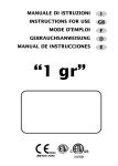
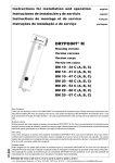
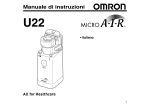
HYDROGENERATOR CRUISING 300 AND CRUISING 600 Installation and instruction manual Version Date Contact V4 JUNE 2015 [email protected] Congratulations ! You have just purchased the most powerful hydrogenerator of its kind. Inspired by the requirements of ocean racing yachts, designed to take into account the stresses experienced by monohulls, this hydrogenerator will radically change your energy management at sea and become your main source of power while sailing. This product has been thoroughly inspected. The product comes with the WATT&SEA warranty described in the "Warranty Terms" chapter of this installation guide. For traceability under the warranty, please register the product on our website: www.wattandsea.com Designed & manufactured in France by: WATT&SEA SARL Z.A. du Bout Blanc 15, rue de la Brigantine 17000 La Rochelle France www.wattandsea.com 35 TABLE OF CONTENTS 1. 37 SAFETY PRECAUTIONS 1.1. ELECTRICAL HAZARDS 1.2. INSTALLATION 1.3. OPERATION 2. CONTENTS OF THE HYDROGENERATOR PACK 37 38 38 39 3. ADDITIONAL EQUIPMENT REQUIRED 40 4. MECHANICAL INSTALLATION 41 4.1. ASSEMBLING THE PROPELLER 4.2. POSITIONING THE HYDROGENERATOR ON THE TRANSOM 4.3. INSTALLING THE CRADLE ON THE TRANSOM 4.4. RIGGING THE IMMERSION/LIFTING SYSTEM 4.5. DISMANTLING THE PROPELLER 4.6. MOUNTING THE ELECTRONIC CONVERTER 5. ELECTRICAL INSTALLATION 41 42 44 45 47 47 48 5.1. THREE-PHASE WIRING OF THE HYDROGENERATOR 5.2. ASSEMBLY OF THE CONVERTER'S POWER SOCKETS 5.3. USING A SOLAR PANEL 5.4. CONNECTING THE CONVERTER TO THE BATTERIES 5.5. INTERPRETATION OF THE CONVERTER'S LEDS 6. INSTALLATION SUMMARY 49 49 50 50 52 53 7. 54 SPECIFICATIONS 7.1. TECHNICAL SPECIFICATIONS OF THE 970 MM AND 610 MM CRUISING 600 7.2. TECHNICAL SPECIFICATIONS OF THE 970 MM AND 610 MM CRUISING 300 7.3. OPERATING PRINCIPLES 7.4. PERFORMANCE 8. MAINTENANCE 54 55 56 57 59 9. 60 LIST OF SPARES 10. F.A.Q. 61 10.1. OPERATION 10.2. MAINTENANCE & REPAIRS 11. WARRANTY 61 63 64 12. FORM FOR REQUESTING AN AFTER-SALES SERVICE RETURN 66 36 1. SAFETY PRECAUTIONS While our primary concern in designing the hydrogenerator was your safety, certain precautions must nevertheless be taken when operating any mechanical or electrical equipment. Please keep the following safety factors in mind when installing and operating the hydrogenerator, and be aware at all times of the electrical and mechanical hazards inherent in operating the propeller. MECHANICAL HAZARDS The hydrogenerator's blades are made of a composite material and can rotate at a speed of over 100 kph (62 mph). At this speed, the blades are practically invisible and can cause serious injuries. WARNING : WHEN INSTALLING THE HYDROGENERATOR, MAKE SURE THAT THE PROPELLER IS SAFELY POSITIONED OUT OF REACH. DO NOT ATTEMPT TO STOP THE PROPELLER WITH YOUR HAND WHILE THE GENERATOR IS RUNNING. 1.1. Electrical hazards Heat in wiring systems often results from undersized cables or faulty connections. Batteries have a very high current carrying capacity. A short-circuit in their cables may result in an outbreak of fire. To prevent this hazard, you must install a 50 amp fuse between the converter and each battery. If the fuse is defective, you must determine the reason before resetting or replacing it. WARNING : YOU MUST INSTALL AN EXTERNAL 50 AMP FUSE. WARNING : ALWAYS PLACE THE HYDROGENERATOR IN THE LIFTED POSITION BEFORE STARTING WORK ON IT. 37 1.2. Installation Please observe the following precautions during installation : • • • Remove the hydrogenerator from the water. Keep safety in mind at all times ! Have someone help you throughout the duration of the installation. Remember : the batteries should be connected last. 1.3. Operation • • Check the support structure, blades and electric circuits on a regular basis. Although the propeller blades are made of very strong materials, they may warp or break if they come into contact with a submerged object. WARNING : NEVER TOUCH THE PROPELLER WHEN IT IS SPINNING. WARNING : NEVER USE THE HYDROGENERATOR TO STEP ONTO OR OFF THE BOAT AS THIS MAY WARP THE DRIVE SHAFT. WARNING : WHEN RUNNING, THE CONVERTER CAN REACH VERY HIGH TEMPERATURES. 38 2. CONTENTS OF THE HYDROGENERATOR PACK Check the contents of your pack against the list below : - 1 HYDROGENERATOR with 5 metres of cable (H-300-03 or H-600-03) - 1 LIFTING BRACKET with cam cleat (K-03) and a locking pin - 1 THREE-BLADE PROPELLER and its extraction kit - 1 CONVERTOR (CV-03) with its bag of connectors : - 1 hydrogenerator connector - 1 solar connector - 3 battery connectors - 4 female contacts - 1 male contact - 2 heat-shrinkable tubes - 1 LOW FRICTION RING with rope - 1 FASTENING KIT (F-03) with 2 stainless steel fork mountings and bolts - 1 INSTRUCTION MANUAL The package and its contents 39 3. ADDITIONAL EQUIPMENT REQUIRED § § § § § § § § 2 Three-phase cable, minimum 3 x 1.5 mm , for connecting the hydrogenerator to the converter. 2 Red and black 10 mm cable for connecting the batteries. 2 Battery terminals for the 10 mm battery cable. 50 Amp fuse or thermal circuit breaker (for example : Series 187 from Blue Sea Systems) Junction box or waterproof connectors for three-phase cables. WATT&SEA offers an optional connection kit with cable and waterproof power socket (Ref. WS-PL-C-002). Bolts for fixing the bracket's stainless steel fork mountings to the hull. Lifting/lowering line (6:1 hoist) with a 6 mm diameter covered line. Install phonic insulation between the transom and the mounting bracket to minimize vibrations. THE QUALITY OF THE POWER SOCKET IS PARAMOUNT : PREFERABLY CHOOSE A PLASTIC MODEL WITH GOLD PLATED CONTACTS QUALIFIED FOR 50 VCC - 12 AMP. DO NOT USE METAL POWER SOCKETS WITH BRASS CONTACTS AS THESE CORRODE TOO QUICKLY. 40 4. MECHANICAL INSTALLATION Your hydrogenerator is shipped partially disassembled. Please read the instruction manual carefully before starting installation. 4.1. Assembling the propeller • • • • Slide the propeller onto the shaft. Check that the stainless steel washer (3) has been pre-mounted at the end of the propeller. If not, insert it. Insert the HSHC M5x20 screw (4) Hold the propeller with one hand and tighten the screw using the 4 mm (5/32") Allen key until the screw starts turning the propeller. 1 N 1 2 2 3 4 3 Designation Shaft Three-blade propeller Stainless steel washer M5x20HSHC screw 4 Exploded view of the shaft, propeller, washer and M5 screw DICATION CONTRAIRE: ES SONT EN MILLIMETRES SURFACE: NCES: RES: AIRES: NOM CASSER LES ANGLES VIFS FINITION: SIGNATURE NE PAS CHANGER L'ECHELLE REVISION ANODISATION DURE DATE TITRE: MATERIAU: MASSE: Hydro Mini présérie Taille CA4 No. DE PLAN AS7G06 ECHELLE:1:5 FEUILLE 1 SUR 1 41 4.2. Positioning the hydrogenerator on the transom Correctly positioning the hydrogenerator is crucial for optimizing its performance. The following criteria must be respected during the installation : • Immersion depth : The hydrogenerator is supplied with a submerged aluminium leg measuring 610 mm (24 in) or 970 mm (38 in). The recommended depth between the surface and the propeller axis is 300 mm (12 in). The greater the depth, the farther the propeller will be from the wake of the hull, and the better the performance of the hydrogenerator. However, the most important the lever arm is, the greater the force on the mountings and during lifting will be. We recommend a length of 970 mm (38 in) as a satisfactory compromise for most monohull installations. The 610 mm leg is suitable for very large monohulls with a device installed on each side. • Flow quality : The quality of water flow is a key element for obtaining satisfactory power output. N.B. : Do not position the hydrogenerator directly in the wake of an appendage or too close to a saildrive. Wherever possible, position the hydrogenerator several inches to the side. • Example of installation with the longer leg (970 mm / 38 in) : BOAT SPEED = 5 knts LOCAL SPEED = 4,75 knts Installation on a 10 m (33 ft) Figaro II heeling at 20° (CFD by CRAIN) The length of 970 mm is enough for it to be immersed properly during listing because the loss of speed due to the wake is about 5%. 42 • Examples of installations with the shorter leg (610 mm / 24 in) : Dual installation on a Pogo40 (© CN STRUCTURES) The hydrogenerators are placed parallel to the rudders but approximately 30 cm (12 in) to the inside to avoid their wakes. Installation on a catamaran (© OUTREMER YACHTING) Here, the hydrogenerator is positioned to the side, out of the wake of the nearby rudder. 43 4.3. Installing the bracket on the transom Depending on your boat's transom, its structure might need to be reinforced to take the stress on the mountings. Phonic insulation also reduces vibrations. WARNING : Due to the size of the lever arm, the maximum theoretical stress on the bracket's fork mountings is estimated at around 300 kg. Your mounting system should be adapted accordingly. The bracket must be adapted to the 8 mm diameter fork mountings that are securely mounted onto the transom. These fork mountings must be mounted in such a way as to compensate for any tilt of the transom. The diagram below will help you to adapt the mountings to your boat. 292,50 408,5 266,50 N.B. : The leg must be vertical in the lowered position. 4x 0 6,1 48 234,1 8,2 0 Lifting Bracket dimensions 44 SAUF INDICATION CONTRAIRE: LES COTES SONT EN MILLIMETRES ETAT DE SURFACE: TOLERANCES: LINEAIRES: ANGULAIRES: NOM CASSER LES ANGLES VIFS FINITION: SIGNATURE DATE NE PAS CHANG TITRE: 4.4. Rigging the immersion/lifting system The hydrogenerator is supplied with a lifting bracket that functions in a similar way to the systems used on the rudders. It facilitates access to the propeller when the device is lifted, for the removal of seaweed for example. The lowering and lifting procedures are carried out using a hoist which is not included in the pack. The maximum traction during lifting is around 40 kg. It is therefore recommended to rig a 6:1 hoist with a 6 mm diameter sheathed line (hoist available in option at Watt&Sea). To minimize the effort, it is advisable to install the low friction ring by tying a cow's hitch knot through the eyelet located under the bracket. • Assembly of the ring on the leg : Pass the rope of the low friction ring through the hole of the leg located under the bracket and attach it with a lark's head knot (see picture below) • Assembly of the lowering rope : Pass the rope successively : - in the cam-cleat of the bracket - in the two gudgeons of the bracket - through the low friction ring - in the hole of the lower gudgeon - Finish the assembly by an eight-knot (see picture below) The cleat integrated into the bracket is used to lock the lowering and lifting line. For permanent blocking, you can use the locking pin. BOUT D’IMMERSION LOWERING ROPE ANNEAU FAIBLE FRICTION LOW FRICTION RING 45 Assembly of the lowering line using a low friction ring N.B. : When the hydrogenerator is submerged, the leg should sit flush in the groove of the gudgeon provided for this purpose. If this is not the case, the lateral support will be less efficient, and this may result in mechanical damage. It is also advisable to hold the lifting end in place using an elastic cord to prevent it from leaving the groove. Lifting the hydrogenerator 46 4.5. Dismantling the propeller To dismantle the propeller, you should use the M6 extractor screw (supplied with the hydrogenerator.) • • Unscrew the M5 screw that holds the propeller at the end of the shaft. In its place, insert the M6 screw and tighten it using the appropriate key. This will have the effect of effortlessly removing the propeller from its conical fitting. N.B. : Any method for dismantling the propeller other than the one described above may result in damage to the hydrogenerator. 4.6. Mounting the electronic converter The electronic converter is a box which is resistant to splashes and passive ventilation, guaranteeing long-term protection even in humid environments. The converter must nevertheless be installed inside the boat, preferably in the mechanical room in close proximity to the batteries. WARNING : WHEN RUNNING, THE CONVERTER CAN REACH VERY HIGH TEMPERATURES. AS SUCH, ASSEMBLY SHOULD BE CARRIED OUT IN A VENTILATED SPACE. N.B. : To ensure proper ventilation, the converter must be mounted on a vertical bulkhead, with the ventilation grids in a vertical position. As it is so light, the converter can be securely attached using the Velcro provided. • degrease the surface on which the converter will be installed • remove the protective tabs of the strips of Velcro provided on the converter • apply the quick-drying glue if the surface is very uneven (against plywood, fibreglass ...) • firmly attach the converter to the surface 47 5. ELECTRICAL INSTALLATION Recommendations for electrical connections : Please consult local/national safety rules before installation. All electric cables must be carefully insulated. For maximum protection, cover the cables with electrical cable sheaths. ed ) WARNING : CONNECTIONS MUST BE INSPECTED REGULARLY TO DETECT SIGNS OF CORROSION AND CLEANED WHEN NECESSARY. ro vi d te r Au x ilia ry ba tte r ie s Co nv er Th re e -p ha se ca bl e (n ot p d) ) ro vi de bo x( no tp tio n nc Ju Optional connexion kit Positive cable Negative cable Three-phase cable (3 x 25mm²) or connection kit (option WATT&SEA) Wiring principle HYDROGENERATOR CONNECTOR CONNECTEUR HYDROGENERATEUR POSITIVE BATTERY #2 CONNECTEUR POSITIF BATTERIE n°2 GND : not used / non utilisé 1 : phase 1 (female contact / contact femelle) 2 : phase 2 (female contact / contact femelle) 3 : phase 3 (female contact / contact femelle) POSITIVE BATTERY #1 CONNECTEUR POSITIF BATTERIE n°1 3 GND 2 1 3 GND 2 1 heat-shrinking tube heat-shrinking tube SOLAR CONNECTOR CONNECTEUR SOLAIRE COMMON BATTERY NEGATIVE CONNECTEUR BATTERIE MOINS DATE: TITLE: 03-2014 CONVERTOR V3 CONNECTION DIAGRAM CONVERTISSEUR V3 SCHEMA DES CONNECTEURS Converter connection 48 GND : solar negative / moins solaire (male contact / contact mâle) 1 : not used / non utilisé 2 : not used / non utilisé 3 : solar positive / plus solaire (female contact / contact femelle) 15 rue de la Brigantine - 17000 La Rochelle - FRANCE tel +33(0)5 46 41 31 99 - [email protected] - www.wattandsea.com SARL au capital de 231 400€ - Siret : 514 026 467 00019 – NAF : 7112B 5.1. Three-phase wiring of the hydrogenerator WARNING : ALWAYS PLACE THE HYDROGENERATOR IN THE LIFTED POSITION BEFORE STARTING WORK ON IT. The hydrogenerator is fitted with a small diameter electrical cable of sufficient length to pass through the transom. This is a three-phase cable. § § § We recommend using the connection kit with a cable and waterproof power socket (Ref. WS-PL-C-002). From here, use a three-phase cable to connect the hydrogenerator to the converter. If the 2 length of this cable is less than 10 metres, use a 3 x 1.5 mm section. Above 10 metres, 2 use a 3 x 2.5 mm section. The converter is connected using the connector kit provided. See the assembly instructions below. 2 N.B. : Using a cable that is less than 3 x 1.5 mm in diameter will affect both the output and the performance of the hydrogenerator. The GND position must not be connected (ground terminal). N.B. : The phase sequence is irrelevant. Therefore, there is no need to take into account the color or numbering of the cables. 5.2. Assembly of the converter's power sockets The converter is supplied with sockets which need to be assembled in accordance with the following procedure: • • • • • • • • • • place a heat shrink boot onto the cable strip the external sheath over 30 mm strip the conductors over 5 mm weld the contacts without allowing the filler to cover the outside of the pin place the hydrogenerator's wires in cavities 1, 2 and 3 for solar panels, place the solar PLUS into cavity 3 and the MINUS on the GND clean the surface of the connector and the cable with alcohol place the heat shrink boot onto the connector shrinke the tube by heating it with a hot air gun leave it to cool 49 1 4 2 5 3 6 Connecting the hydrogenerator's connector 5.3. Using a solar panel The converter has 2 inputs : one for the hydrogenerator and one for the solar panel. The solar panel's maximum voltage must not exceed 50 VCC and the intensity must not exceed 14 amps. When the hydrogenerator and the solar panel generate power at the same time, priority is given to the hydrogenerator. As soon as this is no longer generating power (lifted, the boat is moored) the converter automatically takes into account the solar panel's charge. 5.4. Connecting the converter to the batteries The converter must be placed as close as possible to the batteries in order to minimize losses due to cable length. The maximum recommended distance is 2 metres. The batteries are connected to the converter via a solar connector. The converter has an internal 2 output isolator that makes it possible to charge two battery units separately. The 2 battery banks must be at the same voltage. 50 Italiano Français e fotovoltaico SUNCLIX per Connecteur photovoltaïque SUNCLIX impianti fotovoltaici per cavi destiné câbles pour système à WARNING : RISK OF aux OVERLOADING AND FIRE. ... 16 mm² del tipo PV1-F énergie solaire de 6 ... 16 mm², TYPE AND HAVE THE SAME VOLTAGE. type PV1-F enze di sicurezza RTENZA: I connettori SUNCLIX de- 1 Consignes de sécurité English Deutsch SUNCLIX photovoltaic I/O connector SUNCLIX-Photovoltaik-S installation in photovoltaic systems zumSAME Einsatz in Photovol THEforTWO BATTERY BANKS MUST BE THE for 6 ... 16 mm² solar cables, type PV1-F für 6 ... 16 mm²-Solarkabe 1 Safety notes 1 Sicherheitshinweise WARNING:The SUNCLIX plug-in connecWARNUNG: Die SUNC essere collegati solo da persone che tors may be connected only by trained der dürfen ausschließli ATTENTION : Seules des personnes dûno sotto la supervisione di elettricisti electricians. technisch unterwiesene ment formées en électrotechnique sont alizzati. angeschlossen werden WARNING:Never plug in or disconnect autorisées à installer les connecteurs WARNING BANK MUST BE PROTECTED WITH A 50plug-in AMPconnectors FUSE. under RTENZA: Collegare o scollegare i: EACH BATTERY the SUNCLIX WARNUNG: Stecken o mâles SUNCLIX. ttori SUNCLIX soltanto in assenza di load. SUNCLIX-Steckverbind ATTENTION : Les connecteurs SUNCLIX . Last. NOTE: Use these plug-in connectors only ne doivent jamais être connectés ni déRTANTE: Utilizzare questi connettoin combination with a 6 ... 16 mm² solar caACHTUNG: Verwende connectés en charge. anto insieme a un We cavo solare da ble, type PV1-F. to A safe, electrical connecbinder nur zusammen m IMPORTANTthe : Utiliser ces connecteurs recommend connecting hydrogenerator's converter directly the service battery bank. 6 mm² del tipo PV1-F. Solo con quetion is only possible with this cable. 6 ... 16 mm²-Solarkabe uniquement avec des câbles pour sysvo si garantisce un collegamento When layingother out the cable, observe units, the Nur tème à énergie solaire de 6 ... 16independently mm² et The converter will monitor the batteries of the on-board and willmit diesem Kabel is co sicuro. bending radiuses that the manufacturer rische Anschluss gewä de type PV1-F. Seul ce câble garantit la posa del cavo rispettare i raggi di specifies. Beachten Sie beim Verl sécurité électrique du raccordement. charge them when required. ura prescritti dal produttore. Biegeradien, die der He NOTE: Connect this plug-in connector Lors de la pose du câble, respecter les RTANTE: Collegare questi connetonly with other SUNCLIX photovoltaic ACHTUNG: Verbinden rayons de courbure prescrits par le fabriltanto con altri connettori fotovoltaici plug-in connector. When making the converbinder nur mit ander cant. CLIX. Per il collegamento rispettare nections, be sure to observe the specificaPhotovoltaik-Steckverb IMPORTANT : Raccorder ces connecN.B.sulla : Proper operation on one external battery isolator is not guaranteed and may require utamente le indicazioni tensiotions on nominal voltage and nominal Sie bei dem Verbinden teurs mâles uniquement avec d'autres minale e la corrente nominale. È percurrent. The smallest common value is gaben zu Nennspannun connecteurs photovoltaïques SUNCLIX. additional contactrespecter your distributor. o il più piccolo valore comune. adjustment. permissible. Der kleinste gemeinsam LorsPlease du raccordement, impératisig. RTANTE: Proteggere dalla polvere NOTE: Protect the plug-in connectors vement les valeurs données pour la tenumidità i connettori. from humidity and dirt. ACHTUNG: Schützen S sion nominale et pour l'intensité nominale. binder vor Feuchtigkeit mmergere in acqua i connettori. Le plus petit dénominateur commun est – Do not immerse the plug-in connector in admis. water. – Tauchen Sie die Steckv osare il connettore direttamente sul ter Wasser. di copertura del tetto. IMPORTANT : Protéger les connecteurs – Never lay out the plug directly on the roofde l'humidité et dePOLARITY la saleté. ing. Verlegen Sie den Steck : NEVERmâles REVERSE THE OF THE CONVERTER. THIS WILL LEAD TO– THE are un cappuccioWARNING di sicurezza der Dachhaut. . PV-C PROTECTION CAP, codice – Ne jamais plonger les connecteurs mâles – Attach a protective cap (e.g. DESTRUCTION OF THE 30) ai connettori non collegati. dansDEVICE. l'eau. PV-C PROTECTION CAP, order number – Versehen Sie die Steck 1785430) to plug-in connectors that are gesteckt sind, mit einer – Ne jamais poser directement le connecssione not plugged in. PV-C PROTECTION C teur sur la peau du toit. 1785430). un cacciavite per viti a taglio con una – Equiper les connecteurs mâles non enfi2 Connecting connectors mm (ad es. SZF 1-0,6X3,5; chés d'un capuchon de protection (par ex. 2 Steckverbinder ansc 17). You need a slot screwdriver with a 3-mm wide PV-C PROTECTION CAP, référence blade (e.g. SZF 1-0.6X3.5; item no. 1204517). Sie benötigen einen Schlitz-Sc 1785430). amento del cavo (figura ) 3-mm-breiter Klinge (z. B. SZF 2.1 Connecting the cable (Fig. ) cavo di 18 mm con un utensile adat- 2 Raccordement du connecteur Artikel-Nr. 1204517). endo questa operazione, fare atten• Strip the cable by 18 mm with a suitable tool. Un tournevis à fente à lame large de 3 mm est re2.1 Kabel anschließen (B nançais tagliare i conduttori singoli. Make sure that no individual wires are cut off. English Deutsch quis (par ex. SZF 1-0,6X3,5 ; référence1204517). n cura il conduttore spelato fino a 1 Carefully insert the stripped wire all the way in. • Isolieren Sie das Kabel mit Werkzeug um 18 mm ab. A 2.1 Raccordement du câble (Figure )SUNCLIX-Photovoltaik-Steckverbinder ovoltaïque SUNCLIX SUNCLIX photovoltaic I/O connector estremità dei cavetti devono essere The litz wire ends have to be visible in the dabei keine Einzeldrähte ab elemento di bloccaggio • Dénuder le sur 18 mm avec un outil apspring. es pour système à a molla. for installation incâble photovoltaic systems zum Einsatz in Photovoltaik-Anlagen proprié. Veiller à ne sectionner aucun fil du 1 Führen Sie die abisolierte A bloccaggio a molla. for Ve- 6 ... 16 the spring. Make sureTyp thatPV1-F the spring is mm² solar cables, type PV1-F für 6 ...216 Close mm²-Solarkabel vom e'elemento 6 ... 16dimm², câble. zum Anschlag ein. Die Litze e scatti. snapped in. der Feder sichtbar sein. 1 Introduire 1 Safety notesle fil dénudé avec prudence jusqu'en 1 Sicherheitshinweise serto nel capocorda. 3 Push the insert into the sleeve. butée. Les extrémités des torons doivent appa2 Schließen Sie die Feder. St sécurité a vite per cavo con una WARNING:The SUNCLIX plug-in connecWARNUNG: Die SUNCLIX-Steckverbinconnessione 4 Tighten the cable gland to 3 Nm. raître dans le « tiroir » à ressort. dass die Feder eingerastet tors may be connected only by trained der dürfen ausschließlich durch elektro3 Seules Nm. des personnes dûDE Einbauanweisung 2.2 Assemble the connector 2 electricians. Refermer le « tiroir » à ressort. Vérifier qu'il est 3 Schieben Sie den Einsatz in technisch unterwiesene Personen en deiélectrotechnique connettori sont bien encliqueté. plug in or disconnect • Bring the plug and the socket together. TheEN Installation angeschlossen werden. 4 Ziehen Sie notes die Kabelversch WARNING:Never nstaller les connecteurs ere assieme connettore maschio e connection snaps close thereby.Sie die FR Instructions d'installatio 3 the Enfiler le raccord dans le manchon. an. SUNCLIX plug-in connectors under WARNUNG: Stecken oder trennen eIX. femmina. I connettori si innestano. • Pull on the coupling to check the proper conload. SUNCLIX-Steckverbinder niemals unter IT Istruzioni di installazione 4 Serrer le presse-étoupe à 3 Nm. Lesper connecteurs 2.2 Steckverbinder zusam unto verificare SUNCLIX che il collegamennection. Last. NOTE: Use these plug-in connectors only mais ES Instrucciones de montaj • Führen Sie Stecker und Buc 2.2 Assemblage mâle etto.être connectés ni déin combination withdu a 6 connecteur ... 16 mm² solar caACHTUNG: Verwenden Sie die Steckvercharge. 3 Separating the connector (Fig ) Dabei rastet die Verbindung PT Instruções de instalação • ble, Assembler le connecteur et le connecteur fetype PV1-F. A safe, electrical connecbinder nur zusammen mit einem : Utiliserdei cesconnettori connecteurs zione melle. Veiller à ce que connexion the screwdrivervom as shown in Fig. . RU • Ziehen Sie an der Kupplung tion is only possible withla this cable. s'encli61 ...Insert 16 mm²-Solarkabel Typ PV1-F. vec) des câbles pour sysVerbindung zu prüfen. quète. When laying out the cable, observe the Nur mit diesem Kabel ist der sichere elekt2 Leave screwdriver inserted and disconnect the Montaj talimatı TR e solaire de 6 ... 16 mm² et cacciavite come garantit indicatolain figura . • bending Exercerradiuses une traction deux côtés du raccorthat des the manufacturer rische Anschluss gewährleistet. plug and the socket from each other. . Seul ce câble ZH 3 Steckverbinder trenn dement pour en vérifier la solidité. specifies. Beachten Sie beim Verlegen der Kabel die nserito cacciavite e scollegare il ique duil raccordement. 3.1 Loosen the (Fig.vorgibt. ) 1 Führen Sie den Schraubend Biegeradien, die dercable Hersteller NOTE: Connect this plug-in connector eefemmina connettore du câble,dal respecter les maschio. 3 only Déconnexion du connecteur Bild gezeigt. 1 Screw open the cable with other SUNCLIX photovoltaic mâle ACHTUNG: Verbinden Siegland. diese Steckrbure prescrits par le fabrigamento del cavo (figura ) (Figure ) When making the conplug-in connector. verbinder nur mit anderen SUNCLIX2 Insert the screwdriver at the position shown in 2 Lassen Sie den Schraubend trennen Sie Buchse und Ste beun sure to observe the specificaPhotovoltaik-Steckverbindern. Beachten connessione a vite per cavo. 1 nections, Introduire tournevis comme indiqué à la FiFig. . : Raccorder ces connections voltage and nominal Sie bei dem Verbinden unbedingt die Angureon nominal . niquementnella avecposizione d'autres indicata cacciavite 3.1 Kabel lösen (Bild ) 3 Pryzu theNennspannung connection open pull the sleeve smallest en common value is le gaben undand Nennstrom. SUNCLIX. ahotovoltaïques . 2 current. LaisserThe le tournevis place et séparer the insert apart. Wert ist zuläs1 Drehen Sie die Kabelversch permissible. Derand kleinste gemeinsame dement, respecter impératiconnecteur mâle du connecteur femelle. sul collegamento e staccare il con4 Open the spring with the screwdriver. sig. NOTE: Protect the plug-in connectors 2 Führen Sie den Schraubend eurs données pour la tenmmina dall'inserto. 3.1 câble (Figure ) fromSéparation humidity anddu dirt. ACHTUNG: 5 Remove Schützen the cable. Sie die SteckverBild gezeigten Position e et pour l'intensité nominale. mento di bloccaggio molla con il – 1 Do binder vor Feuchtigkeit und Schmutz. énominateur communa est not immerse the plug-in connector Dévisser le raccord vissé du câble. in 3 Hebeln Sie die Verbindung 4 Technical data Hülse und Einsatz auseinan 2 water. Introduire le tournevis à l'emplacement indiqué – Tauchen Sie die Steckverbinder nicht unter Wasser. e: ilProtéger cavo. les connecteurs Ambient temperature: -40 °C ... +90 °C – Never lay out the à la Figure . plug directly on the roof4 Öffnen Sie die Feder mit de midité et de la saleté. ing. – Verlegen Sie den Stecker nicht direkt auf Nominal voltage: max. 1500 V DC her. 3 Soulever la connexion puis séparer le mancnici der Dachhaut. nger les connecteurs mâles – Attach a protective cap (e.g. Nominal current: 40 A (6 mm²), 50 A (10 mm²), chon du raccord. 5 Entfernen Sie das Kabel. ambiente: -40 °C ... +90 °C PV-C PROTECTION CAP, order number – Versehen Sie die Steckverbinder, die nicht 65 A (16 mm²) 4 1785430) Ouvrir le to « tiroir » àconnectors ressort avec le are tournevis. plug-in that gesteckt sind, mit5,5 einer Schutzkappe (z. B. minale: max. 1500 V DC. er directement le connecCable diameter: ...10 [mm] 4 Technische Daten plugged in. de la connexion. PV-C PROTECTION CAP, Artikel-Nr. Extraire le câble u du toit. inale: 40 A (6 mm²), 50 A (10 mm²), 5 not Umgebungstemperatur: -40 °C 1785430). )nnecteurs mâles non enfi2 Connecting connectors 4 Caractéristiques techniques Nennspannung: max. 1500 V D uchon de protection (par ex. o: 5,5 ...10 mm 1 2 Steckverbinder anschließen Nennstrom: 40 A (6 mm²), 50 A You need a slot screwdriver 3-mm wide Température ambiantewith : -40a °C ... +90 °C CTION CAP, référence 65 A (16 mm²) blade Tension (e.g. SZFnominale 1-0.6X3.5; item no. 1204517). Sie benötigen einen Schlitz-Schraubendreher mit : 1500 V DC max. 3-mm-breiter Klinge (z. B. SZF 1-0,6X3,5; Kabeldurchmesser: 5,5 ...10 m Intensité nominale : 40 A (6 mm²),)50 A (10 mm²), 2.1 Connecting the cable (Fig. nt du connecteur Artikel-Nr. 1204517). 65 the A (16 mm²) • Strip cable by 18 mm with a suitable tool. lame large de 3 mm est re2.1 Kabel anschließen (Bild ) Diamètre de câble : 5,5 ...10 mm Make sure that no individual wires are cut off. 6X3,5 ; référence1204517). 1 Carefully insert the stripped wire all the way in. • Isolieren Sie das Kabel mit einem geeigneten Werkzeug um 18 mm ab. Achten Sie darauf, t du câble (Figure ) The litz wire ends have to be visible in the dabei keine Einzeldrähte abzuschneiden. sur 18 mm avec un outil apspring. 51 e sectionner aucun fil du 1 Führen Sie die abisolierte Ader sorgfältig bis 2 Close the spring. Make sure that the spring is zum Anschlag ein. Die Litzenenden müssen in snapped in. der Feder sichtbar sein. udé avec prudence jusqu'en 3 Push the insert into the sleeve. PV-CF-S6-16 (+)... PV-CM-S6-16 (-)... Biegeradien, die der Hersteller vorgibt. ACHTUNG: Verbinden Sie diese Steckverbinder nur mit anderen SUNCLIXPhotovoltaik-Steckverbindern. Beachten Sie bei dem Verbinden unbedingt die Angaben zu Nennspannung und Nennstrom. Der kleinste gemeinsame Wert ist zulässig. ACHTUNG: Schützen Sie die Steckverbinder vor Feuchtigkeit und Schmutz. – Tauchen Sie die Steckverbinder nicht unter Wasser. – Verlegen Sie den Stecker nicht direkt auf der Dachhaut. – Versehen Sie die Steckverbinder, die nicht gesteckt sind, mit einer Schutzkappe (z. B. PV-C PROTECTION CAP, Artikel-Nr. 1785430). ctor taic he conpecificanal ue is ors ctor in he roof- umber at are wide 17). e tool. cut off. way in. he pring is The r con- g 2 2.1 Kabel anschließen (Bild eeve mm²), 2 18 ) Isolieren Sie das Kabel mit einem geeigneten Werkzeug um 18 mm ab. Achten Sie darauf, dabei keine Einzeldrähte abzuschneiden. 1 Führen Sie die abisolierte Ader sorgfältig bis zum Anschlag ein. Die Litzenenden müssen in der Feder sichtbar sein. 2 Schließen Sie die Feder. Stellen Sie sicher, dass die Feder eingerastet ist. 3 Schieben Sie den Einsatz in die Hülse. 4 Ziehen Sie die Kabelverschraubung mit 3 Nm an. 3 2 1 2.2 Steckverbinder zusammen fügen ) hown in 3 Nm 4 • • . nect the 18 1 Steckverbinder anschließen Sie benötigen einen Schlitz-Schraubendreher mit 3-mm-breiter Klinge (z. B. SZF 1-0,6X3,5; Artikel-Nr. 1204517). • 3 Führen Sie Stecker und Buchse zusammen. Dabei rastet die Verbindung ein. Ziehen Sie an der Kupplung, um die korrekte Verbindung zu prüfen. Steckverbinder trennen (Bild ) 1 Führen Sie den Schraubendreher ein, wie in Bild gezeigt. 2 Lassen Sie den Schraubendreher stecken und trennen Sie Buchse und Stecker voneinander. 3.1 Kabel lösen (Bild ) 1 Drehen Sie die Kabelverschraubung auf. 2 Führen Sie den Schraubendreher an der in Bild gezeigten Position ein. 3 Hebeln Sie die Verbindung auf und ziehen Sie Hülse und Einsatz auseinander. 4 Öffnen Sie die Feder mit dem Schraubendreher. 5 Entfernen Sie das Kabel. 4 Technische Daten Umgebungstemperatur: -40 °C... +90 °C Nennspannung: max. 1500 V DC Nennstrom: 40 A (6 mm²), 50 A (10 mm²), 65 A (16 mm²) Kabeldurchmesser: 5,5 ...10 mm © PHOENIX CONTACT 2012-07-11 MNR 0125154 - 01 10488301 5.5. Interpretation of the converter's LEDs - When the converter is not charging, the battery voltage is indicated by a pulse of color which changes from green (12.8 V) to red (11.5 V). - When the converter is charging, the output power is indicated by a constant color which changes from violet to blue (120W), to light blue (240W) and finally to white (480W). - Green or red colored flashes may overlay the display of the constant color to indicate statuses or anomalies : SITUATION Absorption voltage reached VISUAL 1 brief green flash every 5 seconds COMMENTS The battery is full (absorption voltage =14.3 V / 28.6 V) Floating voltage maintained 1 long green flash every 5 seconds The battery is kept at 100% (floating voltage = 13.8 V / 27.6 V) Overheating 1 red flash every 5 seconds The maximum reached Generator anomaly 2 red flashes every 5 seconds The hydrogenerator's connection is defective at 3 red flashes every 5 seconds The solar panel or the hydrogenerator are applying a voltage that is too high Another anomaly 4 red flashes every 5 seconds Contact your distributor Overvoltage input 52 box temperature has been 6. INSTALLATION SUMMARY The following instructions set out the main steps in the hydrogenerator installation procedure. This is only a summary. Please refer to the appropriate sections of this manual for detailed instructions. 1. Place the propeller onto the device. (See 4.1) 2. Mechanically mount the hydrogenerator onto the transom. (See 4.2) 3. Install a WATT&SEA connector kit with cable and waterproof power socket (Ref. WSPL-C-002). 4. Then, mechanically mount the converter onto a vertical bulkhead, as close as possible to the batteries. (See 4.6) Make sure that the propeller is not submerged and that it is not possible for the alternator to run during installation. 5. Run the converter's power cables through to the batteries. (See 5.4) DO NOT CONNECT the cables to the batteries before installation is complete. 6. Attach the battery connectors, then connect the power cables to the batteries : red wire to the positive terminal, black wire to the negative terminal. (See 5.4) 7. Once the converter is connected to the batteries, the LED will come on indicating the current battery power, from red to green. When the propeller starts turning, the color of the LED will change from violet (10W) to blue (120W) and finally to white (>300W) 53 7. SPECIFICATIONS 7.1. Technical specifications of the 970 mm and 610 mm CRUISING 600 w Hydrogenerator (H-600-03) : Nominal power: 600 W Nominal voltage: Three-phase, 40 V Rated current: 9 A Weight: 8.2 kg / 7.4 kg w Converter (CV-03): Nominal power: 600 W Absorption voltage: 14.3 V / 28.6 V Floating voltage: 13.8 V / 27.6 V Rated current: 44 A / 22 A Solar input: 50 V / 12 A max Weight: 1.5 kg Dim.: 210 x 105 x 60 mm Dimensions of the CRUISING 600 hydrogenerator 54 7.2. Technical specifications of the 970 mm and 610 mm CRUISING 300 w Hydrogenerator (H-300-03): Nominal power: 300 W Nominal voltage: Three-phase, 40 V Rated current: 9 A Weight: 7.1 kg / 6.3 kg w Converter (CV-03): Nominal power: 600 W Absorption voltage: 14.3 V / 28.6 V Floating voltage: 13.8 V / 27.6 V Rated current: 44 A / 22 A Solar input: 50 V / 12 A max Weight: 1.5 kg Dim.: 210 x 105 x 60 mm Dimensions of the CRUISING 300 hydrogenerator 55 7.3. Operating principles • The hydrogenerator : The hydrogenerator consists of a permanent magnet alternator producing a very low three-phase current (0-40 V). This alternator technology allows for very high output, but has the disadvantage of generating high voltages during overspeed. • Protection against overvoltage : To prevent the voltage from surging over 40V, the hydrogenerator is equipped with an electronic system that momentarily short-circuits the alternator during overspeed. This embedded circuit protects the systems located downstream of the alternator. When the hydrogenerator is working overspeed, it produces a very distinctive and audible rumble. This may happen for one of the following reasons : 1 – A cable has been disconnected or the fuse has blown and the converter is no longer connected to the batteries. The hydrogenerator is freewheeling and is no longer slowed by the electromagnetic force. The converter is possibly turned off. 2 – The three-phase cable has become completely disconnected. In this case, the LEDs flash from red, to orange and then to green, indicating that the battery is connected but that there is no power input. 3 – A three-phase wire has become disconnected. In this case, the converter continues to charge but less efficiently. The LEDS must display a constant color ranging from violet, to blue and then to white, on which are surimposed 2 red flashes every 5 seconds. 4 – The batteries are charged or the battery capacity is too weak. The converter has finished charging the batteries or the batteries cannot absorb enough energy to slow down the propeller. The converter indicates this status with a green flash every 5 seconds. 5 – The boat is sailing faster than the propeller speed range and the converter is running at maximum capacity. • The converter : It transforms the alternating current coming from the alternator into a continuous current compatible with the batteries. This voltage is regulated at several levels depending on the state of charge of the batteries. During charging, voltage is regulated at 14.3V / 28.6V (absorption phase). When conditions allow for fully charging the batteries, the converter regulates to a lower voltage (13.8V / 27.6V) to maintain the batteries without damaging them (floating phase). 56 7.4. Performance As detailed in section 4.2 concerning the installation of the hydrogenerator onto the transom, performance very much depends on position and the quality of water flow. The charts given below for the 600 and 300 models correspond with the measurements carried out on a motorboat with 200 mm, 240 mm and 280 mm propellers and a calibrated speedometer. Propeller diameter Maximum operating speed 280 mm 11 knots 240 mm 14 knots 200 mm 18 knots 57 Power output in relation to boat speed The average production values are given for information purposes only and may vary depending on the sea conditions and the quality of the installation. 58 8. MAINTENANCE Originally designed for ocean racing, the hydrogenerator benefits from the latest technology where resistance and reliability are concerned. All metallic parts are made from either specially treated aluminium or A4 stainless steel. Watertightness is guaranteed using cutting-edge industrial gaskets that have a service life of several thousand hours and can easily support circumnavigation of the globe. The housing is filled with a lubricating oil to prevent any water seepage. The hydrogenerator therefore requires no particular maintenance other than cleaning of the external parts. • • • The generator housing should be regularly cleaned and rinsed with fresh water. The generator and propeller mountings should be regularly inspected to ensure that they are tight. The electrical connections should be inspected to ensure that they are tight and corrosion-free. Watt&Sea recommends servicing every two years or every 10,000 miles. For this, Watt&Sea offers servicing packages tailored to your individual needs. For information visit www.wattandsea.com or contact your distributor. REGULARLY INSPECT THE CONDITION OF THE EXTERNAL CONNECTIONS. 59 9. LIST OF SPARES Exploded view of a hydrogenerator REFERENCE G-600-03 G-300-03 CV-03 K-03 P-200-03 P-240-03 P-280-03 EP-03 F-03 FS-03 FI-03 MA-970-03 MA-610-03 TM-03 PI-03 60 DESIGNATION Composite generator 600 W (no propeller) Composite generator 300 W (no propeller) 12-24 VCC auto-detected converter Lifting bracket with cam cleat Cruising three-blade propeller, 200 mm (7.9 in) Cruising three-blade propeller, 240 mm (9.5 in) Cruising three-blade propeller, 280 mm (11 in) Cruising propeller extraction kit Transom mounting kit Upper gudgeon Lower gudgeon Bare aluminium leg 970 mm (38 in) with 2 washers Bare aluminium leg 610 mm (24 in) with 2 washers Leg top plate Locking pin 10. F.A.Q. 10.1. Operation • What power can it produce ? The power generated depends on the size of the propeller and the speed of navigation. The table in section 7.4 gives the output power values in relation to speed for different propeller sizes. The average production values are given for information purposes only and may vary depending on the sea conditions and the quality of the installation. • What drag is to be expected ? The drag depends on the size of the propeller and the speed of navigation. At 6 knots, we estimate that the average drag is 10 kg. To calculate the loss of speed for a particular boat, you need to compare the total drag of the hull at 6 knots with 10 kg of drag of the hydrogenerator at the same speed. Our immersion and lifting trials at a constant speed have not shown any significant difference on the speedometer. • What happens when the batteries are charged ? The electronic regulator automatically charges the batteries. When they are fully charged, the propeller freewheels. and the noise produced by the hydrogenerator changes (thudding sound). • Is the hydrogenerator producing a rumbling sound ? This means that the batteries are fully charged. The hydrogenerator starts to freewheel and produces a thudding, almost rumbling sound. • Is it possible to use the hydrogenerator with the engine ? The system is not designed to replace the engine's alternator. It can nevertheless be used while operating your engine. This presents no mechanical risk. However, electrical output will be significantly disrupted depending on the location of the generator and the water turbulence caused by the engine. • Is it possible to use the hydrogenerator in reverse ? The hydrogenerator must be lifted when reversing the boat in order to avoid any possible damage to the leg and cradle mountings. 61 • The hydrogenerator does not charge as much as is shown in the charts, why is this ? The two most common causes of under-production are : An electrical connection problem : poorly connected/assembled power socket, damaged/corroded socket, cut or pinched cable. The hydrogenerator is positioned along the axis of an appendage (rudder, keel, etc.) which is disrupting the flow of water and affecting production. We suggest that you consult the help centre on our website to check that your device is operating correctly : http://www.wattandsea.com/help-center • Do the converter's LEDS consume energy ? The converter has a residual consumption as one LED is always lit. It cuts out in the event of low voltage (11.9V) in order to save the battery. Generally speaking, you can consider that the standby consumption is less than the self-discharge of the batteries. • Ion lithium batteries ? The converter is designed to charge lithium batteries as its voltage is regulated and cannot exceed the maximum value of 14.3 V (or 28.6 V). It can be programmed with specific voltages, please contact us. 62 10.2. Maintenance & repairs • How reliable is the system ? The reliability of the hydrogenerator has been demonstrated in many ocean and round the world races. It benefits from advanced technological expertise as regards resistance. • What maintenance will the system require ? Except for external cleaning, the hydrogenerator requires no specific maintenance. However, think about : regularly disassembling the propeller to remove any dirt from the shaft checking the condition of the leg's output cable (no of cuts or pinching) checking the condition of external sockets (no corrosion) WATT&SEA recommends servicing every two years or every 10,000 miles. • Can the propeller be replaced ? The propeller can be easily disassembled using the M6 extraction screw provided in the pack. (See 4.5). 63 11. WARRANTY Coverage and warranty period: Our products are designed for very specific conditions of use. It is the responsibility of our customers to ensure the appropriate use of our products. Our systems are covered by a two-year warranty against any manufacturing defect. The warranty period starts on the date of purchase of our products by the distributor. The warranty is limited to the standard replacement of a defective part or, if necessary, the entire system, upon receipt of the part in question. Under civil law, it is the responsibility of the purchaser to fulfil the burden of proof regarding the previous nature of the claimed latent defect. Any returned systems or parts must be accompanied by the warranty returns form (see below), duly completed as follows: name and address of the customer, date of purchase, type of boat, defective parts, description of the structural or design defect, and description of the conditions under which the system was used. Returned systems or parts shall only be accepted with the prior written consent of WATT&SEA, and must be returned by prepaid shipment. Should the replacement of the WATT&SEA product prove to be due to a defect covered by the warranty, these shipment costs shall be refunded. Under no circumstances shall returned systems or parts be refunded; they shall only be replaced. Situations not covered by the warranty: This warranty shall not apply if the system in question: has suffered an accident, or undergone unauthorized alterations or repairs; has not been installed by a professional installer in strict compliance with the procedure specified by WATT&SEA in the installation and user manual supplied with the generator; has been: o installed or serviced in an inappropriate manner, or used under too high a charge; o subjected to abuse or neglect; o used when reversing. The warranty shall not take into account any failures due to simple wear and tear or normal ageing of the structures and materials, any scratches, or any cracks or starring that may appear following an impact. Under no circumstances shall WATT&SEA be liable for any special, incidental or consequential damages. Should you encounter a problem with your WATT&SEA hydrogenerator, please contact your distributor/installer. 64 REGISTER YOUR PRODUCT ONLINE For traceability under www.wattandsea.com. the warranty, please register the product on our website: You will receive the following benefits : * Confirmation of ownership and safety notices : by registering online we can use your saved details to track your product and contact you quickly if necessary. * Product information and news: choose to be among the first to hear about our latest products, product developments and receive helpful advice ! 65 12. FORM FOR REQUESTING AN AFTER-SALES SERVICE RETURN Owner Name: Phone no.: Address: E-mail: Country: Date of purchase of the hydrogenerator: Serial no. (see installation manual) - of the hydrogenerator: - of the converter: Type of boat: Type of assembly on the transom (if custommade, please specify): Conditions of use (frequency/specific conditions having revealed the defect): Defect noticed: Date: Signature: 66 Retailer/Installer Name: Phone no.: Address: E-mail: Country: Date of purchase of the hydrogenerator: Has the defect been confirmed? Has the installation been carried out in compliance with the instruction manual? Installer contact details: Defective subassemblies to be replaced: Date: Signature: After Sales returns authorization no.: 67 68