1
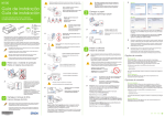
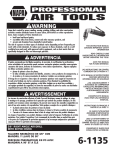
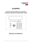
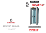
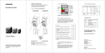
C - 72
User Manual
Instrucciones de Usuario
P
R
O
We thank you to rely on us acquiring a WORK product.
We hope that this demultiplexer offers youa long and
reliable service.
C-72 DMX is an universal signal conversor, able
to convert a DMX digital signal or MIDI in an
analogic signal. So you cann use your analogic
dimmer like a DMX controller or MIDI sequencer.
This demultiplexer can convert up to 72 DMX
signals.
C-72 can be also use like a 72 channels chaser.
You can save an scene into de memory like a
emergency backup.
You dispose an automatic memory if DMX signal
is cut.
CONTROL & FUNCTIONS
Front Panel
3
POWER
FUSE
8
SIGNAL
9
10
11
12
MIDI IN
MIDI THRU
DMX IN
DMX OUT
DMX
HOLD
MIDI
STORE
CHASE
F500MA 250V 5x20MM
1
2
MENU
4
5
6
DMX IN
DMX OUT
7
1 . - POWER SWITCH
2 . - FUSE HOLDER
It contain a fuse type F 0,5A 250V. able to protect the internal supply
3 . - DISPLAY LCD
This seven segments display, shows DMX, MIDI signals and functions like
DMX, HOLD, DMX channel y can e use in order to active
and make changes in the menu.
4 . - BUTTON UP
Pushing this button, we can up in the menu options
5 . - BUTTON MENU
Pushing this button, we activate the system menu
6 . - BUTTON DOWN
Pushing this button, we can down in the menu options
7 . - CHASE BUTTON
This button selects the CHASE mode
8 . - STORE BUTTON
Pushing this button, we can save a scene or call a saved scene
9 . - MIDI IN
We use this connector in order to receive a MIDI signal from a MIDI
controller or sequencer.
10. - MIDI THRU
From this connector we can send the same MIDI connector (9) to another
MIDI device.
11. - DMX IN
XLR- 3 pins connector, we use it to receive DMX signal from a DMX controller.
12. - DMX OUT
XLR- 3 pins connector, we can send the same DMX signal from
connector (11) to another DMX device.
CONTROL & FUNCTIONS
Rear Panel
1
24
25
48
EARTH
49
72
EARTH
OUTPUT LEVEL
EARTH
1
OUTPUTS 1 - 24
13
OUTPUTS 25 - 48
14
ANALOG OUPUT
POLARITY
DIP SWITCH
OUTPUT
2
3
4
10 V
ON
OFF OFF
ON
12 V
ON
OFF
ON
OFF
15 V
ON
ON
OFF
OFF
1
2
3
4
OUTPUTS 49 - 72
15
16
17
18
OPERATING INSTRUCTIONS
MODE SELECT
To access the menu you must hold pressed the MENU button during 3 seconds.
Once in the mode select function, use the UP & DOWN buttons (4 & 6) to select
the DMX or MIDI mode. If a DMX or MIDI signal is present, the correspondant
led will begin blink in the LCD display (3). After choose the DMX or MIDI mode,
press the MENU button (5) to activate the selection.
DMX MODE
When the unit be receiving a DMX signal, the DMX led will begin blink in the LCD
display (3), indicating a DMX signal is present. The unit will show the DMX start
channel in the display. This unit can operate in DMX channels 1-512 (A001A512). Use the UP & DOWN buttons (4 & 6) to select the start DMX channel.
This unit uses 72 DMX channels.
MIDI MODE
When the unit be receiving a MIDI signal, the MIDI led will begin blink in the
display (3) indicating a MIDI signal is present. The unit also will show blinking
the MIDI NOTE NUMBER (CH1-CH16) en el display. This unit can operate with
MIDI notes between 1 to 16. Use the UP & DOWN buttons (4 & 6) to select the
start MIDI note number .
HOLD MODE
This mode allows you to mantain the last DMX configuration, if the signal
interrupts. For example, if the HOLD functionb is turned off and you have the
channels 1 & 4 turned on and then you turn off the controller, the channels 1 &
4 will turn off. If the HOLD function is activated in the same case, the channels
1 & 4 will hold turned on, until you turn off the C 72 DMX or reconnect you
DMX controller. To activate or unactivate the HOLD function :
1.- Hold pressed the MENU button during 3 seconds.
2.- When the LCD display begins blink press twice quickly the MENU button (5)
to activate the HOLD mode setup.
3.- Use the UP & DOWN buttons (4 & 6) to select ON (activated) or OFF
(unactivated).
4.- When finish your selection, press the MENU button (5) three times to exit of
this function and confirm your selection.
PROGRAMMING A SCENE
This function allows you to program a scene in the memory. This scene can be
called in any moment. To program a scene:
1.- With a DMX controller, program a scene using any of the 72 channels
availables.
2.- Hold pressed the SCENE (8) button for 5 seconds until the message GOOD
appears in the LCD display (3).
3.- To recall this scene press the SCENE button. The message STORE will
appear in the LCD display indicating that the unit is executing a saved scene.
CHASE MODE
To activate the CHASE mode press the CHASE button (7), the message CHAS
will appear in the LCD display, indicating that the unit are now executing a 72
channe ls CHASE until this fun ction b e disa bled by the user.
CHANGING THE SIGNAL OUTPUT L,EVEL
This unit is prepared to send analogic signals of +/-10, +/-12 or +/-15 Volts. You
must determine what voltge requires your analogic unit and change the ouput
tension if it is necessary. The predefined output level is 10 Volts. To change the
output level :
1.- Turn off the device.
2.- In the rear panel you can find several switches (16). Use them to select the
output voltage, following this instructions :
To obtain 10 Volts, move the switches 1 & 4 to the ON position.
To obtain 12 Volts, move the switches 2 & 4 to the ON position.
To obtain 15 Volts, move the switches 3 & 4 to the ON position..
3.- In the rear panel is placed a switch of 2 positions (17). Use it to select positive
or negative ouput.
SPEED SETUP
This configuration adjusts the internal CHASE speed. The number of channels
in a CHASE can be adjusted between 1 & 72 channels. This CHASE can not be
edited. To change the CHASE speed:
1.- Hold pressed the MENU button during 3 seconds.
2.- When the LCD display begins to blink, press quickly the MENU button three
times to activate the setup. This will be indicated by the blink of the message
SPXX in the display, where XX is a number.
3.- Use the UP & DOWN buttons (4 & 6) to adjust the speed. The values that
can be selected are between 01 & 99. A configuration of 0 is the fastest
CHASE speed of 0,1 sedconds. A configuration of 99 is the slowest speed
of 10 seconds.
4.- When finish your selection, press the MENU button (5) twice to exit of this
function and confirm your selection.
START CHANNEL SETUP
This configuration allows you to select the start DMX channel which will trigger
the controller. To change this configuration :
1.- Hold pressed the MENU button during 3 seconds.
2.- When the LCD starts to blink, ensure the DMX led placed at the left side of
the display (3) is blinking too. If not, use the UP & DOWN buttons (4 & 6) to
select the DMX mode.
3.- Staying in the DMX mode, press quickly the MENU button (5) once only to
activate the DMX mode. This will be indicated by the message AXXX blinking
in the display.
4.- Use the UP & DOWN buttons (4 & 6) to select the desired start channel. This
channel cab be between 1 to 512.
5.- When finish your selecti press four times the MENU button to exit of this
function and confirm your selection.
13. - 1-24 CHANNEL OUTPUT CONNECTOR
From this 25 pins “D” connector” we can control the
signal output for channel 1 to 24
14. - 25-48 CHANNEL OUTPUT CONNECTOR
From this 25 pins “D” connector” we can control the
signal output for channel 25 to 48
15. - 49-72 CHANNEL OUTPUT CONNECTOR
From this 25 pins “D” connector” we can control the
signal output for channel 49 to 72
16. - OUTPUT LEVEL
OUTPUT LEVEL
Analog output level selector between 10V, 12 V and 15V
DIP SWITCH
OUTPUT
1
2
3
4
10 V
ON
OFF
OFF
ON
12 V
ON
OFF
ON
OFF
15 V
ON
ON
OFF
OFF
1
2
3
4
17. - ANALOGUE OUTPUT POLARITY
ANALOG OUPUT
POLARITY
Analog output polarity selector
START
STEP 1 : With the power turned off, connect a DMX or MIDI
controller.
STEP 2 : Connect the outputs to the “D” connectors (13, 14 &
15) in the rear panel. The 13th connector controls the outputs 1 to
24, the 14th controls the outputs 25 to 48 and the 15th controls the
49 to 72 outputs.
STEP 3 : Use the C 72 DMX to convert the output connectors in
DIN plugs.
STEP 4 : After finish all the connections, turn on the equipment
and follow the instructions of this manual.
TECHNICAL SPECIFICATIONS
Power Supply
AC 230V - 50 Hz.
DMX Signal
3 pins XLR Connector
MIDI Signal
Standar Interface 5 pins
Fuse
0,5 A.
Weight
1,2 Kg
At last, we want remember you:
- Keep the equipmment distanced of damp and avoid entering
any type of liquids into it. If this happens to you with the
equipmment powered on, disconnect it immediatly from the
network.
- Protect this demultiplexer from the warm excessive and the
sun radiation.
- Proccur do not accumulate dust, overall on the connectors.
- Do not put metallic objects into the device.
- If the protection fuse or fuses gets fused, replace them for
another with the same value. Never replace them for fuses with
higher values and do no try to repare it.
- If you install thid device in a rack, ensure that it has a good
ventilation.
P
R
O
Le agradecemos la confianza depositada en nosotros al haber
adquirido un producto WORK.
Esperamos que este Demultiplexor le proporcione un servicio
prolongado y fiable.
El C-72 DMX es un convertidor de señal, universal, que convierte
una señal digital DMX y MIDI en señales analógicas. De este modo
usted puede ultilizar su dimmer analógico con un controlador DMX
o un secuenciador MIDI.
Este demultiplexor puede convertir hasta 72 señales DMX.
El C-72 tambien se puede utilizar como un chaser de 72 canales.
Podemos grabar una escena en la memoria como una copia de
seguridad de emergencia.
Disponemos de una memoria incorporada para el caso de que
accidentalmente se desconecte la unidad.
FUNCIONES Y CONTROL
Panel Frontal
3
POWER
FUSE
8
SIGNAL
9
10
11
12
MIDI IN
MIDI THRU
DMX IN
DMX OUT
DMX
HOLD
MIDI
STORE
CHASE
F500MA 250V 5x20MM
1
2
MENU
4
5
6
DMX IN
DMX OUT
7
1 . - INTERRUPTOR DE ENCENDIDO
Interruptor de encendido y apagado del Demultiplexor.
2 . - PORTAFUSIBLE
Contiene un fusible tipo F 0,5A 250 V. que protege la
alimentación interna del aparato.
3 . - DISPLAY LCD
Este Display LCD de siete segmentos indica señal DMX,
señal MIDI, Función DMX, Función HOLD, Canal DMX y se
utiliza para activar y realizar cambios en en el menú.
4 . - PULSADOR UP
Pulsando este botón podemos ascender en las opciones del
Menu.
5 . - PULSADOR MENU
Utilizando este botón activamos el menu del sistema.
6 . - PULSADOR DOWN
Pulsando este botón podemos descender en las opciones del
Menu.
7 . - PULSADOR CHASE
Este botón selecciona el modo CHASE.
8 . - PULSADOR STORE
Presionando este botón podemos guardar una escena o llamar a
una escena que tenemos guardada.
9 . - ENTRADA MIDI
Este conector lo utilizaremos para recibir una señal MIDI desde un
controlador o un secuenciador MIDI.
10. - MIDI THRU
Desde este conector podemos enviar la misma señal de entrada
del conector MIDI (9) a otro dispositivo MIDI.
11. - ENTRADA DMX
Conector XLR de tres pines que usamos para recibir señal
DMX desde un controlador DMX.
12. - SALIDA DMX
Conector XLR de tres pines desde el que podemos enviar la
misma señal DMX del conector de entrada (11) a otro
dispositivo DMX.
FUNCIONES Y CONTROL
Panel Trasero
1
24
25
48
49
72
EARTH
EARTH
OUTPUT LEVEL
EARTH
1
OUTPUTS 1 - 24
13
OUTPUTS 25 - 48
14
ANALOG OUPUT
POLARITY
DIP SWITCH
OUTPUT
2
3
4
10 V
ON
OFF OFF
ON
12 V
ON
OFF
ON
OFF
15 V
ON
ON
OFF
OFF
1
2
3
4
OUTPUTS 49 - 72
15
16
17
18
INSTRUCCIONES DE MANEJO
SELECCIÓN DE MODO
Para acceder al menú debe mantener presionado el botón de MENU (5) durante,
al menos, tres segundos. Una vez en el selector de MODO use los botones UP
y DOWN (4 y 6) para seleccionar el modo DMX o MIDI. Si hay una señal DMX
o MIDI presente, el correspondiente led comenzará a parpadear en el display
LCD (3). Despues de que haya elegido el modo DMX o MIDI, presione el botón
MENU (5) para activar su selección.
MODO DMX
Cuando la unidad está recibiendo una señal DMX, el led DMX empezará a
parpadear en el siplay LCD (3) indicando que una señal DMX está presente. La
unidad mostrará el canal DMX de arranque en el display. Esta unidad puede
operar con canales DMX 1-512 (A001-A512). Use los botones UP y DOWN
(4 y 6) para seleccionar el canal de arranque DMX. Esta unidad usa un total de
72 canales DMX.
MODO MIDI
Cuando la unidad esté recibiendo una señal MIDI, en este modo el led MIDI
empezará a parpadear en el display (3) indicando la presencia de una señal
MIDI. La unidad tambien mostrará parpadeando el número de NOTA MIDI
(CH1-CH16) en el display. Esta unidad puede operar con notas MIDI de 1 a 16.
Use los botones UP y DOWN (4 y 6) para seleccionar el número de nota MIDI
de arranque.
MODO HOLD
Este modo le permite mantener la última configuración DMX , si la señal se
interrumpe. Por ejemplo si la función HOLD está apagada y usted tiene los
canales 1 y 4 encendidos y apaga su controlador DMX, los canales 1 y 4 se
apagarán. Si activa la función HOLD en el mismo caso los canales 1 y 4 se
mantendrían encendidos hasta que apague el C 72 DMX o reconecte su
controlador DMX. Para activar o desactivar la función HOLD :
1.- Mantenga presionado el botón MENU durante tres segundos.
2.- Cuando el display LCD empiece a parpadear preione rapidamente dos veces
el botón de MENU (5) para activar la configuración de la función HOLD.
3.- Use los botones UP y DOWN (4 y 6) para seleccionar ON (activado) u
OFF (desactivado).
4.- Cuando haya realizado su elección, pulse el botón MENU (5) tres veces
para salir de esta función y confirmar la selección.
PROGRAMAR UNA ESCENA
Esta función le permite programar una escena en la memoria. Esta escena puede
ser llamada en cualquier momento. Para programar una escena :
1.- Con un controlador DMX, programe una escena usando cualquier de los 72
canales disponibles.
2.- Mantenga presionado el botón SCENE (8) durante cinco segundos hasta
que el mensaje GOOD aparezca en el display LCD (3).
3.- Para rellamar a esta escena presione el botón SCENE. El mensaje STORE
aparecera en el display LCD indicando que la unidad está ejecutando la
escena guardada.
MODO CHASE
Para activar el modo CHASE presione el botón CHASE (7), el mensaje CHAS
se mostrara en el display indicando que la unidad está funcionando en modo
CHASE. La unidad ejecutará un CHASE de 72 canales hasta que esta función
sea desconectada.
CAMBIO NIVEL SEÑAL DE SALIDA
Esta unidad está preparada para enviar señales analógicas de +/-10, +/-12 ó
+/-15 Voltios. Determine que voltaje requiere su unidad analógica y cambie la
tensión de salida si es necesario. La salida seleccionada por defecto es de 10
Voltios. Para cambiar el nivel de salida :
1.- Desconecte la alimentación.
2.- En la parte trasera encontrará una serie de switches (16), úselos para
seleccionar la tensión de salida, siguiendo las siguientes instrucciones :
Para obtener 10 Voltios mueva los switches 1 y 4 a la posición de ON.
Para obtener 12 Voltios mueva los switches 2 y 4 a la posición de ON.
Para obtener 15 Voltios mueva los switches 3 y 4 a la posición de ON.
3.- En la parte trasera hay un interruptor de dos posiciones (17). Use este
interruptor para seleccionar salida positiva o negativa.
CONFIGURACIÓN DE VELOCIDAD
Esta configuración ajusta la velocidad del CHASE interno. El número de canales
en un CHASE puede ser ajustado entre 1 y 72 canales. Este CHASE no puede
ser editado. Para cambiar la velocidad del CHASE :
1.- Mantenga presionado el botón de MENU durante tres segundos.
2.- Cuando el display LCD comience a parpadear, presione rapidamente tres
veces el botón de MENU para activar la configuración de velocidad. Esto
será indicado por el parpadeo en el display del mensaje SPXX donde XX
es un número.
3.- Use los botones UP y DOWN (4 y 6) para ajustar la velocidad. Los valores
que se pueden seleccionar se encuentran entre 01 y 99. Una configuración
de 0 es la velocidad más rápida de CHASE de 0,1 segundos. Una
configuración de 99 es la velocidad más lenta de 10 segundos.
4.- Cuando haya realizado su selección, presione el botón de MENU (5) dos
veces para salir de esta función y confirmar su selección.
CONFIGURACIÓN DEL CANAL DE ARRANQUE
Esta configuración le permite seleccionar el canal de arranque DMX que disparará
el controlador. Para cambiar esta configuración :
1.- Mantenga presionado el botón de MENU durante tres segundos.
2.- Cuando el LCD empiece a parpadear, asegurese que el led de DMX situado
a la izquierda del display (3) está parpadeando. Si no lo hace, use los botones
UP y DOWN (4 y 6) para seleccionar el modo DMX.
3.- Estando en el modo DMX, presione rapidamente el botón MENU (5) una
sola vez para activar la cofiguración DMX. Esto sera indicado por el mensaje
AXXX parpadeando en display.
4.- Use los botones UP y DOWN (4 y 6) para seleccionar el canal de arranque
DMX deseado. Este canal puede ser desde el 1 al 512.
5.- Cuando haya realizado su selección presione 4 veces el botón MENU para
salir de esta función y confirmar su selección.
13. - SALIDA CANALES 1 AL 24
Desde este conecto "D" de 25 pines controlamos la señal de salida
de los canales 1 al 24
14. - SALIDA CANALES 25 AL 48
Desde este conecto "D" de 25 pines controlamos la señal de salida
de los canales 25 al 48
15. - SALIDA CANALES 49 AL 72
Desde este conecto "D" de 25 pines controlamos la señal de salida
de los canales 49 al 72
16. - NIVEL DE SALIDA
OUTPUT LEVEL
DIP SWITCH
OUTPUT
1
4
2
3
10 V
ON
OFF
OFF
ON
12 V
ON
OFF
ON
OFF
15 V
ON
ON
OFF
OFF
1
2
3
4
Selector del nivel de salida analógica entre 10 V, 12 V
ó 15 V.
17. - POLARIDAD SALIDA ANALÓGICA
ANALOG OUPUT
POLARITY
Selector de polaridad para la salida de señal analógica
PUESTA EN FUNCIONAMIENTO
PRIMERO : Con la alimentación desconectada, conecte un
controlador DMX o MIDI.
SEGUNDO : Conecte las salidas a los conectores "D" (13, 14 y 15)
en la parte trasera de la unidad. El conector 13 controla las salidas
1 al 24, el 14 controla las salidas 25 al 48 y el 15 lo hace con las
salidas 49 al 72.
TERCERO : Utilice el C 72 DMX para convertir los conectores de
salida en enchufes DIN.
CUARTO : Despues de haber realizado todas las conexiones,
encienda el equipo y siga las instrucciones de este manual.
ESPECIFICACIONES TÉCNICAS
Alimentación
AC 230V - 50 Hz.
Señal DMX
Conector XLR 3 pines
Señal MIDI
Standar Interface 5 pines
Fusible
0,5 A.
Peso
1,2 Kg
Por último queremos recordarle que :
- Mantenga el equipo alejado de la humedad e impida que
penetren en su interior líquidos de cualquier clase. Si le ocurre
ésto estando en marcha su demultiplexor, desconéctelo
inmediatamente de la red.
- Proteja el demultiplexor del calor excesivo y de la radiación
directa del sol.
- Procure que no acumule polvo, sobre todo en los conectores
- No introduzca objetos metálicos en su interior.
- Si el o los fusibles de protección se fundieran, repóngalos por
otros del mismo valor. Nunca repare un fusible.
- Si instala su demultiplexor en un rack, asegúrese de una
ventilación correcta.
Equipson, S.A.
w ww. equi pson. es
[email protected]