1
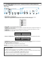
2.4GHz WIRELESS DATA TRANSCEIVER USER MANUAL
MODEL:15-2400RSK
Panel View
1
○
2
○
3
○
4
○
5
○
6
○
7
○
8
○
9
○
10
○
1. DC+12V IN: DC 12V Power Input
2. BAUD RATE and TERMINATION: Baud rate and 120 Ohm termination setting by DIP switch.
(Note: After changing the baud rate by DIP switch, please re-boot the device again.)
3. RS485 PORT: 2-wire Half-Duplex RS485 support.
4. ALARM IN: TTL/CMOS digital Input which could be connected to alarm sensor or digital control signal, e.g.:
Magnetic Reed Switch Detector.
5. ALARM OUT: Reed Relay Output (NC/COM/NO) that could be connected to alarm devices, e.g.: Siren,
Flashing Unit.
6. POWER ON or RF LINK LED: Indicated to power on or RF link status.
Indications
Power On
RF Link Loss
Power/RF LINK LED
On
Low Flashing
7. RS 485 or PAIRING LED: Indicated to RS485 data are transmitted or received and waiting pairing status.
Indications
RS485
Waiting Pairing
Power/RF LINK LED
High Flashing
Low Flashing
8. PAIRING KEY: To set the device into pairing mode. Please do the pairing procedure before connecting the
devices to RS485 network. (Pleas refer to the pairing procedure for more detail.)
9. MASTER or SLAVE: For RF pairing only.
10. ANT: SMA connector for connected to 2.4 GHz antennas.
REMARK: Don’t close 802.11 a/b/g AP router and other 2.4GHz devices.
Pairing procedure:
(1) Make sure these two devices, one is set to “Master” and another is “Slave”.
(2) Please hold the “Pairing KEY” of the master device until the device connected to DC12V power supply
and then you can find the “Pairing LED” of master device is flashing.
(3) Please do the same procedure as step (2) again for the slave device.
(4) When the pairing procedure is complete, the “RF Link LED” of two devices is on.
2. Caution for Installation
2.1 Be careful, never let any water in this equipment.
2.2 If necessary, use a soft cloth moistened with alcohol to wipe off the dust.
2.3 Be extra careful not to shake the unit.
2.4 Avoid places where temperatures exceed 55 o C or higher.
2.5 Avoid places where there are frequent vibrations or shocks.
2.6 When any abnormalities occur, make sure to unplug the unit and contact your local dealer.
3. Packing
3.1 Transceiver
3.2 Antenna
3.3 User manual
3.4 Screws
3.5 Plastic-Conical-Anchor
3.6 Power Adaptor
×2
×2
×1
×8
×8
×2 [Option]
4. Specification
Items
Frequency Channels
RF TX Power
Min. RX Sensitivity
RF Impedance
RS485
Dual Directional
ALARM I/O
Power Consumption
Weight (without antenna)
Operation Temperature
Storage Temperature
Dimensions (W × L × H)
15-2400RSK
2402 ~ 2480 MHz,79-CH (CE/FCC)
100 mW (Average)
-86dBm
50Ω
2-wire RS485 Half Duplex
Data Baud Rate :2400/4800/9600 bps
Fixed Format:1 Start bit, 1 Stop bit, 8 Data Bits, No Parity
-ALARM Input: TTL/CMOS
-ALARM Output:NC/COM/NO (Dry Contact)
Contact Rating: AC 125V / 0.5A ; DC 24V / 1A
60 mA Max. @ DC12V
< 124.8g (4.4 oz)
-10°C ~ 55°C
-30°C ~ 85°C
92 × 75 × 25mm (3.62” × 2.95” × 1.00”)
(excluding connectors and without antenna)
FCC Part 15 Notice:
This equipment has been tested and found to comply with the limits for a Class B digital device, pursuant
to part 15 of the FCC rules. These limits are designed to provide reasonable protection against harmful
interference in a residential installation. This equipment generates, uses and can radiate radio frequency
energy and, if not installed and used in accordance with the instructions, may cause harmful interference
to radio communications. However, there is no guarantee that interference will not occur in a particular
installation. If this equipment does cause harmful interference to radio or television reception, which can
be determined by turning the equipment off and on, the user is encouraged to try to correct the
interference by one or more of the following measures:
-Reorient or relocate the receiving antenna.
-Increase the separation between the equipment and receiver.
-Connect the equipment into an outlet on a circuit different from that to which the receiver is connected.
-Consult the dealer or an experienced radio/TV technician for help.
1.
This Transmitter must not be co-located or operating in conjunction with any other antenna or
transmitter.
2.
This equipment complies with FCC RF radiation exposure limits set forth for an uncontrolled
environment. This equipment should be installed and operated with a minimum distance of 20
centimeters between the radiator and your body.
3.
Any changes or modifications (including the antennas) made to this device that are not expressly
approved by the manufacturer may void the user’s authority to operate the equipment.
Q2011/04/19