1
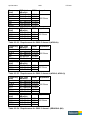
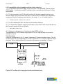
SPECIFICATION PTC 273:2007
REQUIREMENTS FOR
CONNECTION OF ADSL
CPE TO THE TELECOM
NETWORK
Draft for public comment
Telecom New Zealand
April 2007
April 20 2007
2/21
PTC273
CONTENTS
Telecom Disclaimer
4
1. INTRODUCTION
5
1.1. Purpose of this document
5
1.2. Goals of CPE qualification
5
1.3. Field Impact
6
2. DEFINITIONS
7
3. SCOPE
8
4. REFERENCE MODELS
9
5. GENERAL REQUIREMENTS
10
5.1 Supplier Information
6. TELECOM SPECIFIC REQUIREMENTS AND TESTS
10
11
6.1 CPE identification test
11
6.2 PSD compliance test
13
6.3 Basic Performance test
17
6.4 Electrical Safety
18
6.5 EMC
19
6.6 Compatibility with Voice Services on the same line
20
6.7 User Instructions
21
Referenced documents
International standards
[1] Network and Customer Installation Interfaces – ADSL Metallic Interface
ANSI T1.413, 1998
[2] Asymmetric digital subscriber Line (ADSL) transceivers.
ITU G.992.1 (G.dmt),June 1999
Further completed with all Corrigenda and Amendments until December 2003.
[3] Splitterless Asymmetric Digital Subscriber Line (ADSL) Transceivers
ITU G.992.2 (G.lite), June 1999
[4] Asymmetric digital subscriber Line (ADSL) transceivers 2.
ITU G.992.3 (G.dmt.bis), January 2005.
Further completed with Amendments 1 (Sept 05), 2 (Mar 06) and 3 (Nov 06).
[5] Splitterless Asymmetric digital subscriber Line (ADSL) transceivers 2.
ITU G.992.4 (G.lite.bis), July 2002.
[6] Asymmetric digital subscriber Line (ADSL) transceivers - Extended bandwidth ADSL2
(ADSL2+).
ITU G.992.5, January 2005.
Further completed with Amendments 1 (Jul 05), 2 (Jun 06) and 3 (Nov 06).
April 20 2007
3/21
PTC273
[7] Test Procedures for Digital Subscriber Line (DSL) Transceivers
ITU G.996.1 (G.test), February 2001. Completed by Erratum 1 (Jan 03) and Amendment
1 (Mar 03)
[8] Physical layer management for digital subscriber line (DSL) transceivers
ITU G.997.1 (G.ploam), May 2003
Further completed with all Corrigenda and Amendments until November 2006.
[9] Handshake procedures for digital subscriber line (DSL) transceivers
ITU G.994.1 (G.hs), May 2003
Further completed with all Corrigenda and Amendments until November 2006.
[10] Asymmetric Digital Subscriber Line (ADSL) - European specific requirements
ETSI TS 101 388 V1.3.1, May 2002
[11] ADSL Interoperability test plan
Technical report DSL Forum TR-067, May 2004
[12] ADSL2/ADSL2+ Performance Plan Interoperability test plan
Technical report DSL Forum TR-100, March 2007
Telecom PTC documents
[13] Specification PTC 270: 2000
Interim Arrangements for ADSL CPE – Provisional Telepermits
[14] Specification PTC 280: 2001
Interim Telecom Requirements for Customer-connected ADSL Line Filters
April 20 2007
4/21
PTC273
TELECOM DISCLAIMER
While every care has been taken, Telecom nevertheless makes no representation or
warranty, express or implied, with respect to the sufficiency, accuracy, or utility of any
information or opinion contained in this draft Specification. Telecom expressly advises
that the use of or reliance on such information is at the risk of the person concerned.
Telecom shall not be liable for any loss (including consequential loss) damage or injury
incurred by any person or organisation arising out of the sufficiency, accuracy, or utility of
any such information or opinion.
It must be stressed that there is no guarantee of full or continued inter-operability between
Telecom’s network and products granted provisional Telepermits under the terms of this
Specification. In addition, any inter-operability cannot be guaranteed under all operating
conditions likely to be encountered on the Telecom network.
April 20 2007
5/21
PTC273
1. INTRODUCTION
1.1. Purpose of this document
This document presents the minimum conditions to be met by ADSL customer equipment
for connection to Telecom’s ADSL over POTS network. This specification is one of two
specifications covering ADSL CPE, and covers the basic requirements for "permission to
connect" to the Telecom Network. This specification replaces PTC270:2000. A
companion Specification, PTC275, covers the more extensive requirements for
interoperability.
In general, compliance to this specification will not guarantee interoperability between
CPE and DSLAM equipment in all circumstances that can occur in the Telecom network.
However, functional testing does form part of this specification so there can a reasonable
expectation that CPE meeting the requirements will perform adequately on the network. If
field experiences with qualified CPE reveal sources of non-interoperability Telecom
reserves the right to cancel the Telepermit subject to full interoperability testing being
satisfactorily performed. Should general interoperability problems be found, Telecom
reserves the right to amend either this Specification or the Interoperability specification as
appropriate.
1.2 Goals of CPE qualification
The basic purpose of only using qualified ADSL CPE equipment in its network, is to allow
Telecom to fulfil its commitments both to its end-users as service provider as to its ISP
customers as wholesale provider, to offer performing and reliable service in a costeffective way.
The arrival of this new PTC coincides with the introduction of ADSL2plus in the network.
Offering unconstrained bitrate services over ADSL2plus will raise the end-user’s
broadband experiences considerably. Furthermore, it will enable ISP’s to introduce new,
competitive service packages further addressing end-user needs. At the same time,
boosting end-user service offering will raise the bar for all equipment used to deliver the
new services.
Years of experience with ADSL deployment have unveiled the pitfalls and issues related
to ADSL deployment. As with communications systems in general the ultimate
performance limiting factor is noise. This is closely related to signal attenuation, as even in
an otherwise electrical quiet environment a signal is attenuated with distance to the point
that it is indistinguishable from thermal noise which is a function of receiver bandwidth and
temperature. Given this ultimate limit, performance is further limited by induced noise from
other sources between the ATU-C and the ATU-R. For example:
• Interference between different telecommunication equipment (crosstalk), negatively
impacting performance when more systems are deployed in the same cable
binders.
• Bad in-house wiring practices such as untwisted cable, unbalanced wires (e.g. 3wire), loose connections etc leading to signal distortion and even interruption and/or
environmental noise pick-up affecting both performance and stability (service
interruptions and packet loss).
April 20 2007
6/21
PTC273
1.3 Field impact
Telecom cannot guarantee absolutely that compliance to all requirements listed in this
document will not cause any operational problems when deployed in the field. The
fulfilment of this specification has merely to be considered as a baseline and minimal set
of features for offering reliable ADSL connectivity.
April 20 2007
7/21
PTC273
2 Definitions
ADSL1:
This term groups all “legacy” ADSL standards, i.e. ANSI T1.413 Issue 2, ITU
G.992.1 (G.dmt,) and ITU G.992.2 (G.lite,).
ADSL2:
Groups all “new” ADSL standards, i.e. G.992.3 (G.dmt.bis) and G.992.5
(G.lite.bis).
eoc
Embedded Operations Channel: Channel used for signalling control
information between ATU-C and ATU-R.
Interoperability: Two pieces of equipment are dynamically interoperable if they implement
a common and compatible set of features, functions and options and can
demonstrate satisfactory mutual communication in a real network
architecture environment as performance test conditions are varied and
exercised.
Multi-ADSL: Indicates the capability of DSLAM or CPE to operate both according to
ADSL1 as to ADSL2 specification.
Operation Mode: Specific mode out of all up-to-date defined ADSL standards. The set of
operation modes considered in this PTC is listed in section 3 of this
Specification.
Auto-mode: Concept where DSLAM and CPE automatically select best-suited operation
mode out of list of enabled ones, that optimized performance for the
measured loop conditions.
April 20 2007
8/21
PTC273
3. Scope
This PTC replaces PTC270:2000 for all new ADSL CPE equipment to obtain Telepermit
for connection Telecom’s DSL access network.
ADSL CPE that in the past obtained Telepermit based on PTC270:2000, will keep their
right to be deployed in the Telecom network within the limits of operation as were valid
during period of validity of the PTC270:2000. This type of access grant will be referred to
as Restricted Telepermit. This means they will continue to be able to connect to plain
ADSL (G.992.1 or ANSI T1.413 Issue 2) although Telecom will not support applications
other than high-speed Internet access type of services. On the other hand, currently
qualified CPE that are supporting ADSL2plus, can reapply for Telepermit according to new
PTC, and if successfully passing, will obtain Full Telepermit.
All new ADSL CPE types will be required to support following list of operation modes:
• ADSL2plus over POTS – G.992.5 Annex A
• ADSL2 over POTS – G.992.3 Annex A
• READSL2 over POTS – G.992.3 Annex L (M1)
• ADSL1 over POTS (G.992.1 Annex A and ANSI T1.413 Issue 2)
Testing against the requirements of this specification will be performed on a Multi-ADSL
DSLAM, supporting all of above indicated operation modes.
This Specification only covers DSL physical layer requirements. Other requirements, like
higher-layer protocols to be supported, in-house networking interfaces, TR-067
compliance, and so on, fall outside the scope of this document.
Finally, this Specification only covers requirements put on the CPE devices themselves.
Requirements on filters and/or central splitters, wiring practices and other fall outside the
scope of this Specification.
April 20 2007
9/21
PTC273
4. REFERENCE MODELS
TNZ PROFILES
The Multi-ADSL DSLAM will beset to the following profile(s) for testing.
Default profile for Multi-ADSL DSLAM ports :
Datarates
(min-planned-max)
Max. Interl. Delay
Min. INP
Noise Margins
TNZ_MM_Unlimited_NM12dB_interleaved
Upstream
Downstream
32-600-1200 kbps
32-16000-24000 kbps
16 ms
2 symbols
0-12-Inf(51.1)
16 ms
2 symbols
0-12-Inf(51.1)
12 dBm
- 40 dBm/Hz
-37 dBm/Hz
-40 dBm/Hz
No bands configured
None
Disabled
20.4 dBm
-38 dBm/Hz
-32.9 dBm/Hz
-38 dBm/Hz
No, default CO mask
(min-target-max)
Max ATP
Max
ADSL1/2
NOM
READSL2
PSD
ADSL2plus
Cabinet Mask
RFI bands
Carrier Masking
Upstream Power
Back-off
Allowed Operating
modes
G.992.5 Annex A
G.992.3 Annex A, L(M1)
G.992.1 Annex A
T1.413 Issue 2
None
NA
April 20 2007
10/21
PTC273
5. GENERAL REQUIREMENTS
5.1 Supplier Information
Test Item
CPE General Information
vendor information
HW version
SW version
Chipset (Vendor, HW and Firmware)
ADSL Characteristics
supported max rates - downstream
supported max rates – upstream
Supported INP values
used duplex procedure (FDD, EC)
Support of S = ½
Support of trellis
Support of bit swap
Number of latency paths
Power Cut Back implemented? (yes/no)
dying gasp (yes/no)
Other Characteristics
ATM supported
STM supported
TR-069 supported
Compliance
April 20 2007
11/21
PTC273
6. TELECOM SPECIFIC REQUIREMENTS AND TESTS
6.1. CPE identification test
6.1.1 Requirements
(1) It shall be possible to uniquely identify the CPE through the combination of modem
vendor information (as defined in G.994.1) and system vendor information (in eoc channel,
see e.g. G.992.3).
(2) The CPE manufacturer shall ensure that the system vendor information is correctly
filled in. This information should be easy to interpret.
The manufacturer shall describe its methodology of linking system vendor info with actual
CPE types. The methodology should link system vendor info with both HW and firmware
versions of the CPE.
(3) The CPE shall at least support following operation modes G.992.5 Annex A, G.992.3
Annex A, G.992.3 Annex L Mask 1, G.992.1 Annex A.
(4) By default, the CPE shall indicate all operating modes it supports in G.994.1 CLR
message.
(5) Operation modes should not be enabled/disabled by the end-user (via any vendorspecific interface between PC and CPE) but should by default all be allowed. It is up to
the DSLAM and the configured profile to select the appropriate operation mode out of the
list of available modes. The CPE shall follow the operation mode imposed by the DSLAM.
6.1.2 Test rationale
The ability to identify CPE types in invaluable for diagnosing faults. Easily rectified
problems such as running out of date firmware can be easily identified remotely. Also
should interoperability problems occur with specific CPE models, this can easily be
identified, and communicated back to the Telepermit holder.
6.1.3 Test procedure
1. Bring the test port out of service. Configure the test port with default profile. Power
cycle the CPE.
2. Bring the test port in service. Wait until the modem has trained.
3. Retrieve following data on the DSLAM:
Type
Parameter
Far-End System
Vendor
Identification
vendor Id
Far-End
operation mode
capability list
•
version number
serial number
Number of
bytes
8
16
32
Bitmap
Reference
G.994.1 par G.992.3 par
9.3.3.1
9.4.1.4
G.992.3 par 9.4.1.4
G.994.1 par 9.4 (SIF)
The test has to be power-cycled (step 1) too ensure it is not keeping history data. It is allowed that
the CPE uses so-called “warm init” by immediately sending MS from second initialisation on.
April 20 2007
12/21
PTC273
Pass/Fail criteria
Test is successful if:
(a) Operation mode capability list at least indicates the modes required in 6.1.3(3).
(b) Modem and system vendor information of the CPE are available, filled in correctly
and in line with information on identification strategy provided by the vendor to Telecom.
•
This initial test is merely informational for Telecom to identify the CPE under test. Telecom has the
right to request the CPE vendor to change/update the vendor information in case it is ambiguous,
incomplete or same as other equipment already deployed in the Telecom network.
Number of tests
1 initialisation
April 20 2007
13/21
PTC273
6.2. PSD compliance test
6.2.2 Requirements
(1) When operating in ADSL2plus mode, transmit spectrum of CPE shall comply to
G.992.5 Annex A.2.2 (ATU-R upstream transmit spectral mask)
(2) When operating in ADSL2 Annex A mode, transmit spectrum of CPE shall comply to
G.992.3 Annex A.2.2 (ATU-R upstream transmit spectral mask)
(3) When operating in READSL2 M1 mode, transmit spectrum of CPE shall comply to
G.992.3 Annex L.2.2 (ATU-R upstream transmit spectral mask 1 for reach-extended
operation)
(4) When operating in ADSL1 Annex A mode, transmit spectrum of CPE shall comply to
G.992.3 Annex A.2.2 (ATU-R upstream transmit spectral mask)
•
G.992.3 mask is more strict for OOB than ADSL1, and thus less impacting ADSL2plus and HDB3 on
frequencies above 1.1 Mhz. Telecom requires to have same OOB PSD when operated in ADSL1
operation mode.
PSD
(dBm/Hz)
-32.9 dBm/Hz peak PSD
-34.5 dBm/Hz peak PSD
22.13 dB/octave
-72 dB/octave
21.5 dB/octave
-48 dB/octave
peak PSD, RBW = 1 MHz
-97.5 peak
+15 dBrn
0-4 kHz
-90 dBm/Hz peak PSD, RBW = 10kHz
-100 dBm/Hz peak PSD, RBW = 10kHz
-91.3 dBm/Hz
-93.2 dBm/Hz
-110 dBm/Hz
-92.5 dBm/Hz
4
25.875
103.5
-112 dBm/Hz
181.7 307 686
12211411 1630
5275
138 243
G992.5 (ADSL2+)
G992.3 (ADSL2, ADSL1)
G992.3 (ADSL2 Annex L Mask 1)
Figure 6.2.2 ATU-R Transmitter PSD
Frequency Requirement Measurement conditions
(kHz)
0-4
-75 dBm
Total power (0 - 4 kHz) into 600 Ohms
-97.5 dBm/Hz RBW 12.5 Hz into 100 Ohms
Table 6.2.2.1 0 - 4 kHz requirement for all modulations
12000
Frequency
(kHz)
April 20 2007
14/21
Frequency
(kHz)
4
25.875
138
243
686
12000
PSD Limit
(dBm/Hz)
-92.5 dBm/Hz
-34.5 dBm/Hz
-34.5 dBm/Hz
-93.2 dBm/Hz
-100 dBm/Hz
-100 dBm/Hz
Frequency
(kHz)
1411
1630
5275
12000
PSD Limit
(dBm/Hz)
-100 dBm/Hz
-110 dBm/Hz
-112 dBm/Hz
-112 dBm/Hz
RBW
Impedance
100 Hz
100 Hz
10 kHz 100 Ohms
10 kHz
10 kHz
10 kHz
RBW
Impedance
1 MHz
1 MHz 100 Ohms
1 MHz
1 MHz
Table 6.2.2.2 Requirements for G992.5 Annex A (ADSL2+)
Frequency
(kHz)
4
25.875
138
307
12000
PSD Limit
(dBm/Hz)
-92.5 dBm/Hz
-34.5 dBm/Hz
-34.5 dBm/Hz
-90 dBm/Hz
-90 dBm/Hz
Frequency
(kHz)
1221
1630
12000
PSD Limit
(dBm/Hz)
-90 dBm/Hz
-110 dBm/Hz
-110 dBm/Hz
RBW
Impedance
100 Hz
100 Hz
10 kHz 100 Ohms
10 kHz
10 kHz
RBW
Impedance
1 MHz
1 MHz 100 Ohms
1 MHz
Table 6.2.2.3 Requirements for G992.3 Annex A (ADSL2, ADSL1))
Frequency
(kHz)
4
25.875
103.5
181.7
686
12000
PSD Limit
(dBm/Hz)
-92.5 dBm/Hz
-32.9 dBm/Hz
-32.9 dBm/Hz
-91.3 dBm/Hz
-100 dBm/Hz
-100 dBm/Hz
Frequency
(kHz)
1411
1630
5275
12000
PSD Limit
(dBm/Hz)
-100 dBm/Hz
-110 dBm/Hz
-112 dBm/Hz
-112 dBm/Hz
RBW
Impedance
100 Hz
100 Hz
10 kHz 100 Ohms
10 kHz
10 kHz
10 kHz
RBW
Impedance
1 MHz
1 MHz 100 Ohms
1 MHz
1 MHz
Table 6.2.2.4 Requirements for G992.3 Annex L (READSL2 (M1)
PTC273
April 20 2007
15/21
PTC273
26.2.3 Test rationale
Compliance to spectral masks is required to limit interference with other services using the
same cable.
6.2.4 Test procedure
To carry out the following tests, connect the equipment under test to an ATU-C via a
suitable resistive attenuator, with a spectrum analyser. See Figure 6.2.4.1 and 6.2.4.2.
For the 0-4 kHz measurements, a Telecom splitter should be used (Figure 6.2.4.1) to prevent the much
higher power upstream passband overloading the probe. Similarly, at the higher frequencies, a high pass
filter may be necessary.
The attenuation should be increased until, the ATU-C spectrum is attenuated sufficiently
to allow the ATU-R output to be measured.
•
To measure the ADSL1, ADSL2 Annex A and ADSL2+ spectra, the modems may have to be forced
to transmit these specific modulations. ADSL2 AnnexL however cannot be set in the modem, but
with sufficient attention, the DSLAM should automatically select this mode.
-50 dB
100 : 100 ohm
ATU-R
Telecom Splitter
0-4 kHz, 600 Ohm
Selective Level
Meter
Figure 6.2.4.1
Setup for testing voice band power
ATU-C
April 20 2007
16/21
-50 dB
100 : 100 ohm
ATU-R
PTC273
ATU-C
Differential probe
Spectrum
Analyser
Figure 6.2.4.2
Setup for testing above voice band
To be verified
In-band compliance of mask
4 tests to be performed:
ADSL2plus, ADSL2 Annex A, LM1, ADSL1 against Multi-Mode DSLAM
April 20 2007
17/21
PTC273
6.3. Basic Performance test
6.3.1 Requirement
This test sets the minimum downstream performance to be achieved by the modem on a
typical customer line.
6.3.2 Test rationale
This test case is designed to give an indication that the modem will connect to a Telecom
DSLAM and exceed a minimal data rate. This test is not a comprehensive performance
test, but eliminates any product which is not fit for purpose.
6.3.3 Test procedure
This test uses Telecom cable between the Test Laboratory and the nearest Telecom
ADSL2+ DSLAM.
1. Measure downstream speed of a reference modem
2. Connect modem under test and measure downstream speed
3. Repeat steps 1 and 2
The time between each test shall be not more than 5 minutes
6.3.4 Result
The average speed of the two tests of the modem under test shall be not less than 60% of
the average speed of the two tests of the reference modem.
April 20 2007
18/21
PTC273
6.4. Electrical safety
(1) The electrical safety requirements of AS/NZ 60950 shall be complied with by all CPE
items covered by this Specification.
(2) Test reports to AS/NZ 60950 or its equivalent shall be supplied by a testing laboratory
which is either recognised by Office of the Chief Electrical Engineer of the Ministry of
Consumer Affairs (a division of the Ministry of Economic Development), or which is
accredited by IANZ or one of its affiliated overseas laboratory registration authorities for
electrical safety testing.
•
A considerable proportion of telecommunications equipment now available was originally
manufactured for the North American and Japanese markets, where the mains voltage is only 100110 V. Such overseas equipment is often designed with inadequate internal clearances between its
components to meet New Zealand electrical safety requirements, which are based on 230 V
operation.
(3) Any separate external power supply used shall also comply with the requirements of
AS/NZ 60950 or its equivalent.
(4) Any separate external power supply used shall be suitably labelled so that it is easily
and positively identifiable as being associated with the modem.
•
The power supply is critical to the performance of the modem, and it cannot be substituted for
generic power supplies of similar rating.
April 20 2007
19/21
PTC273
6.5. EMC compliance
(1) The requirements of AS/NZ 55022 (CISPR 22 or its direct overseas equivalent) shall
be complied with by all CPE items covered by this Specification.
• The New Zealand requirements for general EMC compliance by items of equipment
intended to be installed in customer’s premises are the same as those applicable in most
overseas countries, including Australia, which most suppliers seem to regard as a single
market with New Zealand. As such, test reports acceptable in New Zealand will generally
already be available as the result of testing carried out for other markets.
(2) It is a regulatory requirement that test reports to AS/NZS 55022 or its equivalent shall
be held by suppliers of this class of equipment and that a formal Declaration of Conformity
shall be submitted to the Ministry of Economic Development before such products are
offered for sale or put into use in this country.
April 20 2007
20/21
PTC273
6.6. Compatibility with voiceband services on the same line
(1) POTS band requirements apply at the POTS port of the standard Telecom remote
POTS splitter. Conformance shall be verified by test in accordance with Annex A of this
specification.
(2) The line termination of ATU-R shall include a DC isolating capacitor having a one
minute voltage rating no less than 400 Vdc, in relation to the voiceband input impedance
requirement that the imaginary part shall be in the range -1.1 to -2.0 kohm at 4 kHz.
•
Reference: G.992.1 Annex A.4.2.1 and A.4.1.
(3) The DC resistance at 250 V dc shall not be less than 5 Mohm.
(4) The longitudinal balance at the line termination of the ATU-R shall exceed 40 dB over
the frequency range 30 kHz to 2208 kHz.
•
Ref G.992.1 Annex A.4.3.1
(4) Operation in the presence of interference from POTS services
The application of POTS network ringing and POTS CPE ring trip shall not cause the
modem to re-sync.
Test Procedure
Using the configuration in Fig 6.6, send 5 cadences of Telecom standard ringing. The line
is then looped with the designated AC and DC impedance for 15 seconds, then the loop is
removed. After a further period of 15 seconds, the sequence is repeated, 25 times.
Figure 6.6 Test Set up for ringing and on-hook/off-hook tests
April 20 2007
21/21
PTC273
6.7 User Instructions
Clear User Instructions shall be supplied with every modem. These shall be specific to
connection to the Telecom network. They may be part of the full user manual or a New
Zealand set up supplement. The basic minimum setup data is contained on the Telepermit
website at: http://www.telepermit.co.nz/ADSLModemSetUp.html
The test laboratory shall set up the modem using the instructions supplied, and note any
deficiencies or ambiguities.