1
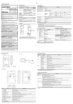
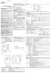
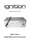
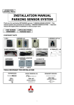
JY997D23401D Side B ENGLISH Related Manuals 3. Specifications 6. Driver Installation When using the conversion adaptor, prepare the following manual as well. As GT10 User's Manual and GT Designer2 Version2 Basic Operation Data Transfer Manual are sold separately, inquire at our local distributor for it. For details of a PLC to be connected, refer to the PLC user’s manual respectively. 3.1 Operating atmosphere Procedure for installing the driver is explained below. Windows® XP installation follows. • Windows® 98, Windows® 98SE, Windows® Millennium Edition, and Windows® 2000, the installation method will vary. Installation of the driver is canceled during the following process, the installation is not carried out correctly. If the installation is canceled, uninstall the driver and install again. Please refer to Chapter 8 for instructions on uninstalling the driver. RS-232 / USB Conversion adaptor Manual name USER’S MANUAL Manual Number JY997D23401D Date Sep 2008 This manual describes the part names, external dimensions and specifications of the product. Before use, read this manual and manuals of relevant products fully to acquire proficiency in handling and operating the product. Make sure to learn all the product information, safety information, and precautions. And, store this manual in a safe place so that you can take it out and read it whenever necessary. Always forward it to the end user. Registration The company name and the product name to be described in this manual are the registered trademarks or trademarks of each company. Effective Sep 2008 Specifications are subject to change without notice. GT10 User’s Manual GT Designer2 Version2 Basic Operation/ Data Transfer Manual Manual Number (Model Code) Contents JY997D24701 (09R819) Describes the GT10 hardware-relevant content such as part names, external dimensions, mounting, wiring, specifications, and introduction to option devices. 3.2 Performance Specifications Describes methods of the GT SH-080529ENG Designer2 installation operation, basic operation for drawing and transmitting (1D7M24) data to GOT1000 series : Indispensable manual For the manuals relevant to GOT1000, refer to the PDF manuals stored in the screen creation software used. For details about a PLC to be connected, refer to the manuals of PLCs respectively. For the FA transparent functionality, refer to the GX Developer Version Operating Manual. © 2008 Mitsubishi Electric Corporation Bundled Items Safety Precaution (Read these precautions before using.) Product GT10-R2TUSB 5S RS-232/USB conversion adaptor This manual classify the safety precautions into two categories: Included items USB driver software (CD-ROM) User's Manual (this manual) . Indicates that incorrect handling may cause hazardous conditions, resulting in death or severe injury. Indicates that incorrect handling may cause hazardous conditions, resulting in medium or slight personal injury or physical damage. The conversion adaptor convert the GOT's RS-232 interface to USB, thereby enabling the transparent functionality to transfer and monitor the sequence program, and the project data transfer between the GT10 main unit and the PC. Use this conversion adaptor with the GT09-C30USB-5P type USB cable. may also be DISPOSAL PRECAUTIONS • When disposing of the product, handle it as industrial waste. TRANSPORTATION PRECAUTIONS • Make sure to transport the conversion adaptor and/or relevant unit(s) in the manner they will not be exposed to the impact exceeding the impact resistance described in the general specifications of this manual, as they are precision devices. Failure to do so may cause the unit to fail. Check if the unit operates correctly after transportation. 3) The following screen is displayed. 115,200/ 57,600/ 38,400/ 19,200/ 9,600/ 4,800 bps Connector shape To GOT Supply voltage RS-232 side DC5V ± 5% (from GOT) USB side DC5V ± 5% (from PC) Power consumption RS-232 side 200mW (40mA/DC5V) USB side 275mW (55mA/DC5V) Please install the driver with the following procedure. 1) When the USB cable is connected to the personal computer, the following screen is displayed. (Installation of the software for USB driver) MINI DIN 6Pins (Male) To USB cable USB MINI-B 5Pins (Receptacle) 3.3 System Requirements (Communication driver) OS Microsoft® Windows®98, Windows®98SE Microsoft® Windows®Millennium Edition (Windows® Me) Microsoft® Windows®2000 Microsoft® Windows®XP Software GT Designer2 GX Developer Product name Model name USB cable GT09-C30USBMitsubishi Electric System Service Co, LTD 5P (3m) Personal computer Communication driver 2) Installing Conversion adapter GOT 1) 15 Name Specifications 1) RS-232 Connector MINI-DIN 6 Pins (male) : For connecting GOT 2) USB Connector USB MINI : For connecting USB cable 3) Display LED (POWER) Green: Lit when the power is properly supplied (Lit when connected to the PC with a USB cable) 4) Display LED (SD) Red: Lit while sending data (GOT → PC) 5) Display LED (RD) Red: Lit while receiving data (PC → GOT) • If using Windows® 98, Windows® 98SE, Windows® Millennium Edition or Windows® 2000 A screen that is equivalent to the one below is displayed by clicking [ My Computer ] → [ Control Panel ] → [ System ] → [ Device Manager ] in the menu of the personal computer. + USB cable for connecting a personal computer (Mitsubishi Electric System Service Co, LTD) 5. Connecting Procedure 1) Turn the GOT power off. 2) Connect the RS-232 connector of the conversion adaptor to the GOT. 3) Connect the USB MINI-B connector of the USB cable to the conversion adaptor. 4) Connect the USB A connector of the USB cable to the personal computor. 5) Turn the GOT power on. 6) Make sure the display LED (POWER) lamp of the conversion adaptor is lit. (The display LED (POWER) lamp of conversion adaptor lights when power is supplied normally by the personal computer.) • Connectiong to FXCPU 1) Click [ Online ] → [ Transfer Setup ] . 2) Double-click [ Serial ] of PC side I/F. 3) Check [ RS-232C ]. Select the same COM number as the COM number of the personal computer when the setting COM number screen appears. Click [ OK ]. B Check following: - GT10-RS2TUSB-5S is indicated at A). - GT10-RS2TUSB-5S (COM *) is indicated at B). * indicates the COM number used in Conversion adapter. - Install the driver again when is displayed. Select the programming software COM number as the COM number currently assigned on the screen above. 7.2 Setting Software 7.2.1 Setting GT Designer2 Click [ Communication ] → [ To/From GOT... ] → [ Communication configuration tab ] → [ RS232 ]. Select the same COM number as the COM number of the personal computer when the setting communication port screen appears. Click [ OK ] . Click [ Next > ]. The installation of the USB Serial Port software will begin. - If using Windows® 2000, a screen to select the location of the installation files is displayed. Please select the CD-ROM drive. 5) The screen of 2) is displayed. (Only in Windows® XP) Click [ Continue Anyway ]. 6) The following screen is displayed. 7.2.2 Click [ Continue Anyway ]. 9. Troubleshooting If communication cannot be established between the GOT and a PC using conversion adaptor, confirm the following status by checking display LED in conversion adaptor. State of POWER LED Contents POWER LED is lit. The DC5V power supply from the personal computer is normally supplied. In case of no communication, check the status of SD LED and RD LED. POWER LED is not lit. The DC 5V power supply from the personal computer is not supplied. Check the items below. • Confirm that the specified cable is used to connect the personal computer. • Check that the OS is running on the PC. The status of SD LED and RD LED. A Click [ Finish ]. If using Windows® 2000 or Windows® XP, proceed to step 4). - If Windows® 98, Windows® 98SE or Windows® Millennium Edition is used, installation of the USB Serial Port software begins, and ends automatically. The CD-ROM can be removed from the personal computer at this time. The installation of the USB driver software is finished. 4) The following screen is displayed. Insert the included CD-ROM into the personal computer's CD-ROM drive. Click [ Next > ]. The installation of the USB driver software will begin. - If using Windows® 98, Windows® 98SE, Windows® Millennium Edition, and Windows® 2000, A window to select the location of the installation files. Please select the CD-ROM drive. 2) The following screen is displayed. (Only in Windows® XP) USB port 75 (2.95") Unit : mm (inch) Weight : Approx.40g No. Note: This product requires USB Driver Installation for each USB port to be connected. To use multiple USB ports, connect this product to each port, and install the driver individually. (Depending on the PC environment, Driver installation may be done automatically.) 23 (0.9") GOT (RS-232) 24 (0.94") 6 (0.23") USB2.0 (For full speed) Transmission speed (0.59") • Do not disassemble or modify the conversion adaptor. Doing so can cause a failure, malfunction, injury or fire. • Do not touch the conductive and electronic parts of the conversion adaptor directly. Doing so can cause a unit malfunction or failure. • When unplugging the conversion adaptor connected to the unit, do not hold and pull the cable portion. Doing so can cause the unit or cable to be damaged or can cause a malfunction due to a cable connection fault. 200 (7.87") 5) φ12 STARTUP/MAINTENANCE PRECAUTIONS 40 (1.57") RS-232 GT10 4) RD 3) MOUNTING PRECAUTIONS • Use the conversion adaptor in the environment that satisfies the general specifications described in GT10 User's Manual. Never use the product in areas with excessive dust, oily smoke, conductive dusts, corrosive gas (salt air, Cl 2 , H 2 S, SO 2 or NO 2 ), flammable gas, vibration or impacts, or exposed to high temperature, condensation, or rain and wind. Not doing so can cause an electric shock, fire, malfunction or product damage or deterioration. Bidirectional between RS-232 and USB Communication GOT Type PC 4. System Configuration 2. Part Names and External Dimensions SD Depending on circumstances, procedures indicated by linked to serious results. In any case, it is important to follow the directions for usage. Level Conversion 3.4 USB cable (sold separately) 1. Overview POWER and Must be free of lamp black, corrosive gas, flammable gas, or excessive amount of electroconductive dust particles and must be no direct sunlight. (Same as for saving) General specifications are the same as the GT10 main unit. For general specifications, refer to the GT10 main unit manual. B JAPANESE RD A (RS-232) Side SD B POWER Side Communicating correctly Extinguished • Confirm the personal computer and the GOT are connected properly with the specified cable. • Check that the software settings on the PC are correct. Refer to the Section7.2 Setting software. For details on software setting procedures, refer to the respective software manual. . Blinking Data receiving Extinguished • Confirm that the power is supplied to GOT. • Confirm the personal computer and the GOT are connected properly with the specified cable. • Check that the software settings on the PC are correct. Refer to the Section7.2 Setting software. For details on software setting procedures, refer to the respective software manual. . 8. Method for Uninstalling Driver The procedure for uninstalling the driver is explained below. A Windows® XP example follows. Please uninstall the driver by the procedure below. 1) Detach the USB cable from the personal computer. On the PC display, click [ Start ] → [ Control Panel ] → [ Add or Remove Programs ] → [GT10-RS2TUSB-5S Drivers]. The window below appears.. - In case of Windows® Me of Windows® 98 and Windows® 98SE and Windows® Millennium Edition , Windows® 2000 A screen that is equivalent to the one below is displayed by clicking [ My Computer ] → [ Control Panel ] → [ Add/Remove Programs ] in the menu of the personal computer. SD RD Contents Blinking * When the driver softwares for FX-USB-AW/FX3U-USB-BD and GT10-RS2TUSB5S are installed, uninstalling one of these driver softwares may cause the other not to function properly. When this happens, reinstall the driver software. * When driver installation is required after already establishing USB communication. → This product requires USB Driver Installation for each USB port to be connected. Connect the product to a driver-installed USB port, or install the driver to the current port. Setting GX Developer • Connectiong to Q/QnACPU 1) Click [ Online ] → [ Transfer Setup ] . 2) Double-click [ PLC module ] of PLC side I/F. 3) Check [ via GOT [ direct coupled ] transparent mode ]. Click [ Change/Remove ]. 2) The following screen is displayed. This manual confers no industrial property rights or any rights of any other kind, nor does it confer any patent licenses. Mitsubishi Electric Corporation cannot be held responsible for any problems involving industrial property rights which may occur as a result of using the contents noted in this manual. 4) Double-click [ Serial ] of PC side I/F. Check [ RS-232 ]. Select the same COM number as the COM number of the personal computer when the setting COM number screen appears. Click [ OK ] . Click [ Continue ]. 3) The following screen is displayed. Click [ Finish ]. The installation of the USB Serial Port software will finish. The CD-ROM (USB driver software) can be removed from the personal computer at this time. For safe use • This product has been manufactured as a general-purpose part for general industries, and has not been designed or manufactured to be incorporated in a device or system used in purposes related to human life. • Before using the product for special purposes such as nuclear power, electric power, aerospace, medicine or passenger movement vehicles, consult with Mitsubishi Electric. • This product has been manufactured under strict quality control. However when installing the product where major accidents or losses could occur if the product fails, install appropriate backup or failsafe functions in the system. 7. Installation Confirmation of Driver, Setting Software 7.1 Installation Confirmation of Driver Procedure for confirming the installation of the driver is described below. Windows® XP example follows. • In Windows® XP, click [ Start ] → [ Settings ] → [ Control Panel ] → [ Peformance and Maintenance ] → [ System ] → [ Hardware ] →[ Device Manager (D) ] and the window below will be displayed. Please confirm the COM number to which the USB driver is allocated (COM and LPT). Warranty Mitsubishi will not be held liable for damage caused by factors found not to be the cause of Mitsubishi; opportunity loss or lost profits caused by faults in the Mitsubishi products; damage, secondary damage, accident compensation caused by special factors unpredictable by Mitsubishi; damages to products other than Mitsubishi products; and to other duties. Click [ Finish ]. HEAD OFFICE : TOKYO BUILDING, 2-7-3 MARUNOUCHI, CHIYODA-KU, TOKYO 100-8310, JAPAN HIMEJI WORKS : 840, CHIYODA CHO, HIMEJI, JAPAN JY997D23401D Side B ENGLISH Related Manuals 3. Specifications 6. Driver Installation When using the conversion adaptor, prepare the following manual as well. As GT10 User's Manual and GT Designer2 Version2 Basic Operation Data Transfer Manual are sold separately, inquire at our local distributor for it. For details of a PLC to be connected, refer to the PLC user’s manual respectively. 3.1 Operating atmosphere Procedure for installing the driver is explained below. Windows® XP installation follows. • Windows® 98, Windows® 98SE, Windows® Millennium Edition, and Windows® 2000, the installation method will vary. Installation of the driver is canceled during the following process, the installation is not carried out correctly. If the installation is canceled, uninstall the driver and install again. Please refer to Chapter 8 for instructions on uninstalling the driver. RS-232 / USB Conversion adaptor Manual name USER’S MANUAL Manual Number JY997D23401D Date Sep 2008 This manual describes the part names, external dimensions and specifications of the product. Before use, read this manual and manuals of relevant products fully to acquire proficiency in handling and operating the product. Make sure to learn all the product information, safety information, and precautions. And, store this manual in a safe place so that you can take it out and read it whenever necessary. Always forward it to the end user. Registration The company name and the product name to be described in this manual are the registered trademarks or trademarks of each company. Effective Sep 2008 Specifications are subject to change without notice. GT10 User’s Manual GT Designer2 Version2 Basic Operation/ Data Transfer Manual Manual Number (Model Code) Contents JY997D24701 (09R819) Describes the GT10 hardware-relevant content such as part names, external dimensions, mounting, wiring, specifications, and introduction to option devices. 3.2 Performance Specifications Describes methods of the GT SH-080529ENG Designer2 installation operation, basic operation for drawing and transmitting (1D7M24) data to GOT1000 series : Indispensable manual For the manuals relevant to GOT1000, refer to the PDF manuals stored in the screen creation software used. For details about a PLC to be connected, refer to the manuals of PLCs respectively. For the FA transparent functionality, refer to the GX Developer Version Operating Manual. © 2008 Mitsubishi Electric Corporation Bundled Items Safety Precaution (Read these precautions before using.) Product GT10-R2TUSB 5S RS-232/USB conversion adaptor This manual classify the safety precautions into two categories: Included items USB driver software (CD-ROM) User's Manual (this manual) . Indicates that incorrect handling may cause hazardous conditions, resulting in death or severe injury. Indicates that incorrect handling may cause hazardous conditions, resulting in medium or slight personal injury or physical damage. The conversion adaptor convert the GOT's RS-232 interface to USB, thereby enabling the transparent functionality to transfer and monitor the sequence program, and the project data transfer between the GT10 main unit and the PC. Use this conversion adaptor with the GT09-C30USB-5P type USB cable. may also be DISPOSAL PRECAUTIONS • When disposing of the product, handle it as industrial waste. TRANSPORTATION PRECAUTIONS • Make sure to transport the conversion adaptor and/or relevant unit(s) in the manner they will not be exposed to the impact exceeding the impact resistance described in the general specifications of this manual, as they are precision devices. Failure to do so may cause the unit to fail. Check if the unit operates correctly after transportation. 3) The following screen is displayed. 115,200/ 57,600/ 38,400/ 19,200/ 9,600/ 4,800 bps Connector shape To GOT Supply voltage RS-232 side DC5V ± 5% (from GOT) USB side DC5V ± 5% (from PC) Power consumption RS-232 side 200mW (40mA/DC5V) USB side 275mW (55mA/DC5V) Please install the driver with the following procedure. 1) When the USB cable is connected to the personal computer, the following screen is displayed. (Installation of the software for USB driver) MINI DIN 6Pins (Male) To USB cable USB MINI-B 5Pins (Receptacle) 3.3 System Requirements (Communication driver) OS Microsoft® Windows®98, Windows®98SE Microsoft® Windows®Millennium Edition (Windows® Me) Microsoft® Windows®2000 Microsoft® Windows®XP Software GT Designer2 GX Developer Product name Model name USB cable GT09-C30USBMitsubishi Electric System Service Co, LTD 5P (3m) Personal computer Communication driver 2) Installing Conversion adapter GOT 1) 15 Name Specifications 1) RS-232 Connector MINI-DIN 6 Pins (male) : For connecting GOT 2) USB Connector USB MINI : For connecting USB cable 3) Display LED (POWER) Green: Lit when the power is properly supplied (Lit when connected to the PC with a USB cable) 4) Display LED (SD) Red: Lit while sending data (GOT → PC) 5) Display LED (RD) Red: Lit while receiving data (PC → GOT) • If using Windows® 98, Windows® 98SE, Windows® Millennium Edition or Windows® 2000 A screen that is equivalent to the one below is displayed by clicking [ My Computer ] → [ Control Panel ] → [ System ] → [ Device Manager ] in the menu of the personal computer. + USB cable for connecting a personal computer (Mitsubishi Electric System Service Co, LTD) 5. Connecting Procedure 1) Turn the GOT power off. 2) Connect the RS-232 connector of the conversion adaptor to the GOT. 3) Connect the USB MINI-B connector of the USB cable to the conversion adaptor. 4) Connect the USB A connector of the USB cable to the personal computor. 5) Turn the GOT power on. 6) Make sure the display LED (POWER) lamp of the conversion adaptor is lit. (The display LED (POWER) lamp of conversion adaptor lights when power is supplied normally by the personal computer.) • Connectiong to FXCPU 1) Click [ Online ] → [ Transfer Setup ] . 2) Double-click [ Serial ] of PC side I/F. 3) Check [ RS-232C ]. Select the same COM number as the COM number of the personal computer when the setting COM number screen appears. Click [ OK ]. B Check following: - GT10-RS2TUSB-5S is indicated at A). - GT10-RS2TUSB-5S (COM *) is indicated at B). * indicates the COM number used in Conversion adapter. - Install the driver again when is displayed. Select the programming software COM number as the COM number currently assigned on the screen above. 7.2 Setting Software 7.2.1 Setting GT Designer2 Click [ Communication ] → [ To/From GOT... ] → [ Communication configuration tab ] → [ RS232 ]. Select the same COM number as the COM number of the personal computer when the setting communication port screen appears. Click [ OK ] . Click [ Next > ]. The installation of the USB Serial Port software will begin. - If using Windows® 2000, a screen to select the location of the installation files is displayed. Please select the CD-ROM drive. 5) The screen of 2) is displayed. (Only in Windows® XP) Click [ Continue Anyway ]. 6) The following screen is displayed. 7.2.2 Click [ Continue Anyway ]. 9. Troubleshooting If communication cannot be established between the GOT and a PC using conversion adaptor, confirm the following status by checking display LED in conversion adaptor. State of POWER LED Contents POWER LED is lit. The DC5V power supply from the personal computer is normally supplied. In case of no communication, check the status of SD LED and RD LED. POWER LED is not lit. The DC 5V power supply from the personal computer is not supplied. Check the items below. • Confirm that the specified cable is used to connect the personal computer. • Check that the OS is running on the PC. The status of SD LED and RD LED. A Click [ Finish ]. If using Windows® 2000 or Windows® XP, proceed to step 4). - If Windows® 98, Windows® 98SE or Windows® Millennium Edition is used, installation of the USB Serial Port software begins, and ends automatically. The CD-ROM can be removed from the personal computer at this time. The installation of the USB driver software is finished. 4) The following screen is displayed. Insert the included CD-ROM into the personal computer's CD-ROM drive. Click [ Next > ]. The installation of the USB driver software will begin. - If using Windows® 98, Windows® 98SE, Windows® Millennium Edition, and Windows® 2000, A window to select the location of the installation files. Please select the CD-ROM drive. 2) The following screen is displayed. (Only in Windows® XP) USB port 75 (2.95") Unit : mm (inch) Weight : Approx.40g No. Note: This product requires USB Driver Installation for each USB port to be connected. To use multiple USB ports, connect this product to each port, and install the driver individually. (Depending on the PC environment, Driver installation may be done automatically.) 23 (0.9") GOT (RS-232) 24 (0.94") 6 (0.23") USB2.0 (For full speed) Transmission speed (0.59") • Do not disassemble or modify the conversion adaptor. Doing so can cause a failure, malfunction, injury or fire. • Do not touch the conductive and electronic parts of the conversion adaptor directly. Doing so can cause a unit malfunction or failure. • When unplugging the conversion adaptor connected to the unit, do not hold and pull the cable portion. Doing so can cause the unit or cable to be damaged or can cause a malfunction due to a cable connection fault. 200 (7.87") 5) φ12 STARTUP/MAINTENANCE PRECAUTIONS 40 (1.57") RS-232 GT10 4) RD 3) MOUNTING PRECAUTIONS • Use the conversion adaptor in the environment that satisfies the general specifications described in GT10 User's Manual. Never use the product in areas with excessive dust, oily smoke, conductive dusts, corrosive gas (salt air, Cl 2 , H 2 S, SO 2 or NO 2 ), flammable gas, vibration or impacts, or exposed to high temperature, condensation, or rain and wind. Not doing so can cause an electric shock, fire, malfunction or product damage or deterioration. Bidirectional between RS-232 and USB Communication GOT Type PC 4. System Configuration 2. Part Names and External Dimensions SD Depending on circumstances, procedures indicated by linked to serious results. In any case, it is important to follow the directions for usage. Level Conversion 3.4 USB cable (sold separately) 1. Overview POWER and Must be free of lamp black, corrosive gas, flammable gas, or excessive amount of electroconductive dust particles and must be no direct sunlight. (Same as for saving) General specifications are the same as the GT10 main unit. For general specifications, refer to the GT10 main unit manual. B JAPANESE RD A (RS-232) Side SD B POWER Side Communicating correctly Extinguished • Confirm the personal computer and the GOT are connected properly with the specified cable. • Check that the software settings on the PC are correct. Refer to the Section7.2 Setting software. For details on software setting procedures, refer to the respective software manual. . Blinking Data receiving Extinguished • Confirm that the power is supplied to GOT. • Confirm the personal computer and the GOT are connected properly with the specified cable. • Check that the software settings on the PC are correct. Refer to the Section7.2 Setting software. For details on software setting procedures, refer to the respective software manual. . 8. Method for Uninstalling Driver The procedure for uninstalling the driver is explained below. A Windows® XP example follows. Please uninstall the driver by the procedure below. 1) Detach the USB cable from the personal computer. On the PC display, click [ Start ] → [ Control Panel ] → [ Add or Remove Programs ] → [GT10-RS2TUSB-5S Drivers]. The window below appears.. - In case of Windows® Me of Windows® 98 and Windows® 98SE and Windows® Millennium Edition , Windows® 2000 A screen that is equivalent to the one below is displayed by clicking [ My Computer ] → [ Control Panel ] → [ Add/Remove Programs ] in the menu of the personal computer. SD RD Contents Blinking * When the driver softwares for FX-USB-AW/FX3U-USB-BD and GT10-RS2TUSB5S are installed, uninstalling one of these driver softwares may cause the other not to function properly. When this happens, reinstall the driver software. * When driver installation is required after already establishing USB communication. → This product requires USB Driver Installation for each USB port to be connected. Connect the product to a driver-installed USB port, or install the driver to the current port. Setting GX Developer • Connectiong to Q/QnACPU 1) Click [ Online ] → [ Transfer Setup ] . 2) Double-click [ PLC module ] of PLC side I/F. 3) Check [ via GOT [ direct coupled ] transparent mode ]. Click [ Change/Remove ]. 2) The following screen is displayed. This manual confers no industrial property rights or any rights of any other kind, nor does it confer any patent licenses. Mitsubishi Electric Corporation cannot be held responsible for any problems involving industrial property rights which may occur as a result of using the contents noted in this manual. 4) Double-click [ Serial ] of PC side I/F. Check [ RS-232 ]. Select the same COM number as the COM number of the personal computer when the setting COM number screen appears. Click [ OK ] . Click [ Continue ]. 3) The following screen is displayed. Click [ Finish ]. The installation of the USB Serial Port software will finish. The CD-ROM (USB driver software) can be removed from the personal computer at this time. For safe use • This product has been manufactured as a general-purpose part for general industries, and has not been designed or manufactured to be incorporated in a device or system used in purposes related to human life. • Before using the product for special purposes such as nuclear power, electric power, aerospace, medicine or passenger movement vehicles, consult with Mitsubishi Electric. • This product has been manufactured under strict quality control. However when installing the product where major accidents or losses could occur if the product fails, install appropriate backup or failsafe functions in the system. 7. Installation Confirmation of Driver, Setting Software 7.1 Installation Confirmation of Driver Procedure for confirming the installation of the driver is described below. Windows® XP example follows. • In Windows® XP, click [ Start ] → [ Settings ] → [ Control Panel ] → [ Peformance and Maintenance ] → [ System ] → [ Hardware ] →[ Device Manager (D) ] and the window below will be displayed. Please confirm the COM number to which the USB driver is allocated (COM and LPT). Warranty Mitsubishi will not be held liable for damage caused by factors found not to be the cause of Mitsubishi; opportunity loss or lost profits caused by faults in the Mitsubishi products; damage, secondary damage, accident compensation caused by special factors unpredictable by Mitsubishi; damages to products other than Mitsubishi products; and to other duties. Click [ Finish ]. HEAD OFFICE : TOKYO BUILDING, 2-7-3 MARUNOUCHI, CHIYODA-KU, TOKYO 100-8310, JAPAN HIMEJI WORKS : 840, CHIYODA CHO, HIMEJI, JAPAN JY997D23401D Side B ENGLISH Related Manuals 3. Specifications 6. Driver Installation When using the conversion adaptor, prepare the following manual as well. As GT10 User's Manual and GT Designer2 Version2 Basic Operation Data Transfer Manual are sold separately, inquire at our local distributor for it. For details of a PLC to be connected, refer to the PLC user’s manual respectively. 3.1 Operating atmosphere Procedure for installing the driver is explained below. Windows® XP installation follows. • Windows® 98, Windows® 98SE, Windows® Millennium Edition, and Windows® 2000, the installation method will vary. Installation of the driver is canceled during the following process, the installation is not carried out correctly. If the installation is canceled, uninstall the driver and install again. Please refer to Chapter 8 for instructions on uninstalling the driver. RS-232 / USB Conversion adaptor Manual name USER’S MANUAL Manual Number JY997D23401D Date Sep 2008 This manual describes the part names, external dimensions and specifications of the product. Before use, read this manual and manuals of relevant products fully to acquire proficiency in handling and operating the product. Make sure to learn all the product information, safety information, and precautions. And, store this manual in a safe place so that you can take it out and read it whenever necessary. Always forward it to the end user. Registration The company name and the product name to be described in this manual are the registered trademarks or trademarks of each company. Effective Sep 2008 Specifications are subject to change without notice. GT10 User’s Manual GT Designer2 Version2 Basic Operation/ Data Transfer Manual Manual Number (Model Code) Contents JY997D24701 (09R819) Describes the GT10 hardware-relevant content such as part names, external dimensions, mounting, wiring, specifications, and introduction to option devices. 3.2 Performance Specifications Describes methods of the GT SH-080529ENG Designer2 installation operation, basic operation for drawing and transmitting (1D7M24) data to GOT1000 series : Indispensable manual For the manuals relevant to GOT1000, refer to the PDF manuals stored in the screen creation software used. For details about a PLC to be connected, refer to the manuals of PLCs respectively. For the FA transparent functionality, refer to the GX Developer Version Operating Manual. © 2008 Mitsubishi Electric Corporation Bundled Items Safety Precaution (Read these precautions before using.) Product GT10-R2TUSB 5S RS-232/USB conversion adaptor This manual classify the safety precautions into two categories: Included items USB driver software (CD-ROM) User's Manual (this manual) . Indicates that incorrect handling may cause hazardous conditions, resulting in death or severe injury. Indicates that incorrect handling may cause hazardous conditions, resulting in medium or slight personal injury or physical damage. The conversion adaptor convert the GOT's RS-232 interface to USB, thereby enabling the transparent functionality to transfer and monitor the sequence program, and the project data transfer between the GT10 main unit and the PC. Use this conversion adaptor with the GT09-C30USB-5P type USB cable. may also be DISPOSAL PRECAUTIONS • When disposing of the product, handle it as industrial waste. TRANSPORTATION PRECAUTIONS • Make sure to transport the conversion adaptor and/or relevant unit(s) in the manner they will not be exposed to the impact exceeding the impact resistance described in the general specifications of this manual, as they are precision devices. Failure to do so may cause the unit to fail. Check if the unit operates correctly after transportation. 3) The following screen is displayed. 115,200/ 57,600/ 38,400/ 19,200/ 9,600/ 4,800 bps Connector shape To GOT Supply voltage RS-232 side DC5V ± 5% (from GOT) USB side DC5V ± 5% (from PC) Power consumption RS-232 side 200mW (40mA/DC5V) USB side 275mW (55mA/DC5V) Please install the driver with the following procedure. 1) When the USB cable is connected to the personal computer, the following screen is displayed. (Installation of the software for USB driver) MINI DIN 6Pins (Male) To USB cable USB MINI-B 5Pins (Receptacle) 3.3 System Requirements (Communication driver) OS Microsoft® Windows®98, Windows®98SE Microsoft® Windows®Millennium Edition (Windows® Me) Microsoft® Windows®2000 Microsoft® Windows®XP Software GT Designer2 GX Developer Product name Model name USB cable GT09-C30USBMitsubishi Electric System Service Co, LTD 5P (3m) Personal computer Communication driver 2) Installing Conversion adapter GOT 1) 15 Name Specifications 1) RS-232 Connector MINI-DIN 6 Pins (male) : For connecting GOT 2) USB Connector USB MINI : For connecting USB cable 3) Display LED (POWER) Green: Lit when the power is properly supplied (Lit when connected to the PC with a USB cable) 4) Display LED (SD) Red: Lit while sending data (GOT → PC) 5) Display LED (RD) Red: Lit while receiving data (PC → GOT) • If using Windows® 98, Windows® 98SE, Windows® Millennium Edition or Windows® 2000 A screen that is equivalent to the one below is displayed by clicking [ My Computer ] → [ Control Panel ] → [ System ] → [ Device Manager ] in the menu of the personal computer. + USB cable for connecting a personal computer (Mitsubishi Electric System Service Co, LTD) 5. Connecting Procedure 1) Turn the GOT power off. 2) Connect the RS-232 connector of the conversion adaptor to the GOT. 3) Connect the USB MINI-B connector of the USB cable to the conversion adaptor. 4) Connect the USB A connector of the USB cable to the personal computor. 5) Turn the GOT power on. 6) Make sure the display LED (POWER) lamp of the conversion adaptor is lit. (The display LED (POWER) lamp of conversion adaptor lights when power is supplied normally by the personal computer.) • Connectiong to FXCPU 1) Click [ Online ] → [ Transfer Setup ] . 2) Double-click [ Serial ] of PC side I/F. 3) Check [ RS-232C ]. Select the same COM number as the COM number of the personal computer when the setting COM number screen appears. Click [ OK ]. B Check following: - GT10-RS2TUSB-5S is indicated at A). - GT10-RS2TUSB-5S (COM *) is indicated at B). * indicates the COM number used in Conversion adapter. - Install the driver again when is displayed. Select the programming software COM number as the COM number currently assigned on the screen above. 7.2 Setting Software 7.2.1 Setting GT Designer2 Click [ Communication ] → [ To/From GOT... ] → [ Communication configuration tab ] → [ RS232 ]. Select the same COM number as the COM number of the personal computer when the setting communication port screen appears. Click [ OK ] . Click [ Next > ]. The installation of the USB Serial Port software will begin. - If using Windows® 2000, a screen to select the location of the installation files is displayed. Please select the CD-ROM drive. 5) The screen of 2) is displayed. (Only in Windows® XP) Click [ Continue Anyway ]. 6) The following screen is displayed. 7.2.2 Click [ Continue Anyway ]. 9. Troubleshooting If communication cannot be established between the GOT and a PC using conversion adaptor, confirm the following status by checking display LED in conversion adaptor. State of POWER LED Contents POWER LED is lit. The DC5V power supply from the personal computer is normally supplied. In case of no communication, check the status of SD LED and RD LED. POWER LED is not lit. The DC 5V power supply from the personal computer is not supplied. Check the items below. • Confirm that the specified cable is used to connect the personal computer. • Check that the OS is running on the PC. The status of SD LED and RD LED. A Click [ Finish ]. If using Windows® 2000 or Windows® XP, proceed to step 4). - If Windows® 98, Windows® 98SE or Windows® Millennium Edition is used, installation of the USB Serial Port software begins, and ends automatically. The CD-ROM can be removed from the personal computer at this time. The installation of the USB driver software is finished. 4) The following screen is displayed. Insert the included CD-ROM into the personal computer's CD-ROM drive. Click [ Next > ]. The installation of the USB driver software will begin. - If using Windows® 98, Windows® 98SE, Windows® Millennium Edition, and Windows® 2000, A window to select the location of the installation files. Please select the CD-ROM drive. 2) The following screen is displayed. (Only in Windows® XP) USB port 75 (2.95") Unit : mm (inch) Weight : Approx.40g No. Note: This product requires USB Driver Installation for each USB port to be connected. To use multiple USB ports, connect this product to each port, and install the driver individually. (Depending on the PC environment, Driver installation may be done automatically.) 23 (0.9") GOT (RS-232) 24 (0.94") 6 (0.23") USB2.0 (For full speed) Transmission speed (0.59") • Do not disassemble or modify the conversion adaptor. Doing so can cause a failure, malfunction, injury or fire. • Do not touch the conductive and electronic parts of the conversion adaptor directly. Doing so can cause a unit malfunction or failure. • When unplugging the conversion adaptor connected to the unit, do not hold and pull the cable portion. Doing so can cause the unit or cable to be damaged or can cause a malfunction due to a cable connection fault. 200 (7.87") 5) φ12 STARTUP/MAINTENANCE PRECAUTIONS 40 (1.57") RS-232 GT10 4) RD 3) MOUNTING PRECAUTIONS • Use the conversion adaptor in the environment that satisfies the general specifications described in GT10 User's Manual. Never use the product in areas with excessive dust, oily smoke, conductive dusts, corrosive gas (salt air, Cl 2 , H 2 S, SO 2 or NO 2 ), flammable gas, vibration or impacts, or exposed to high temperature, condensation, or rain and wind. Not doing so can cause an electric shock, fire, malfunction or product damage or deterioration. Bidirectional between RS-232 and USB Communication GOT Type PC 4. System Configuration 2. Part Names and External Dimensions SD Depending on circumstances, procedures indicated by linked to serious results. In any case, it is important to follow the directions for usage. Level Conversion 3.4 USB cable (sold separately) 1. Overview POWER and Must be free of lamp black, corrosive gas, flammable gas, or excessive amount of electroconductive dust particles and must be no direct sunlight. (Same as for saving) General specifications are the same as the GT10 main unit. For general specifications, refer to the GT10 main unit manual. B JAPANESE RD A (RS-232) Side SD B POWER Side Communicating correctly Extinguished • Confirm the personal computer and the GOT are connected properly with the specified cable. • Check that the software settings on the PC are correct. Refer to the Section7.2 Setting software. For details on software setting procedures, refer to the respective software manual. . Blinking Data receiving Extinguished • Confirm that the power is supplied to GOT. • Confirm the personal computer and the GOT are connected properly with the specified cable. • Check that the software settings on the PC are correct. Refer to the Section7.2 Setting software. For details on software setting procedures, refer to the respective software manual. . 8. Method for Uninstalling Driver The procedure for uninstalling the driver is explained below. A Windows® XP example follows. Please uninstall the driver by the procedure below. 1) Detach the USB cable from the personal computer. On the PC display, click [ Start ] → [ Control Panel ] → [ Add or Remove Programs ] → [GT10-RS2TUSB-5S Drivers]. The window below appears.. - In case of Windows® Me of Windows® 98 and Windows® 98SE and Windows® Millennium Edition , Windows® 2000 A screen that is equivalent to the one below is displayed by clicking [ My Computer ] → [ Control Panel ] → [ Add/Remove Programs ] in the menu of the personal computer. SD RD Contents Blinking * When the driver softwares for FX-USB-AW/FX3U-USB-BD and GT10-RS2TUSB5S are installed, uninstalling one of these driver softwares may cause the other not to function properly. When this happens, reinstall the driver software. * When driver installation is required after already establishing USB communication. → This product requires USB Driver Installation for each USB port to be connected. Connect the product to a driver-installed USB port, or install the driver to the current port. Setting GX Developer • Connectiong to Q/QnACPU 1) Click [ Online ] → [ Transfer Setup ] . 2) Double-click [ PLC module ] of PLC side I/F. 3) Check [ via GOT [ direct coupled ] transparent mode ]. Click [ Change/Remove ]. 2) The following screen is displayed. This manual confers no industrial property rights or any rights of any other kind, nor does it confer any patent licenses. Mitsubishi Electric Corporation cannot be held responsible for any problems involving industrial property rights which may occur as a result of using the contents noted in this manual. 4) Double-click [ Serial ] of PC side I/F. Check [ RS-232 ]. Select the same COM number as the COM number of the personal computer when the setting COM number screen appears. Click [ OK ] . Click [ Continue ]. 3) The following screen is displayed. Click [ Finish ]. The installation of the USB Serial Port software will finish. The CD-ROM (USB driver software) can be removed from the personal computer at this time. For safe use • This product has been manufactured as a general-purpose part for general industries, and has not been designed or manufactured to be incorporated in a device or system used in purposes related to human life. • Before using the product for special purposes such as nuclear power, electric power, aerospace, medicine or passenger movement vehicles, consult with Mitsubishi Electric. • This product has been manufactured under strict quality control. However when installing the product where major accidents or losses could occur if the product fails, install appropriate backup or failsafe functions in the system. 7. Installation Confirmation of Driver, Setting Software 7.1 Installation Confirmation of Driver Procedure for confirming the installation of the driver is described below. Windows® XP example follows. • In Windows® XP, click [ Start ] → [ Settings ] → [ Control Panel ] → [ Peformance and Maintenance ] → [ System ] → [ Hardware ] →[ Device Manager (D) ] and the window below will be displayed. Please confirm the COM number to which the USB driver is allocated (COM and LPT). Warranty Mitsubishi will not be held liable for damage caused by factors found not to be the cause of Mitsubishi; opportunity loss or lost profits caused by faults in the Mitsubishi products; damage, secondary damage, accident compensation caused by special factors unpredictable by Mitsubishi; damages to products other than Mitsubishi products; and to other duties. Click [ Finish ]. HEAD OFFICE : TOKYO BUILDING, 2-7-3 MARUNOUCHI, CHIYODA-KU, TOKYO 100-8310, JAPAN HIMEJI WORKS : 840, CHIYODA CHO, HIMEJI, JAPAN